Not sure if this is the correct area or a allowable question. Please delete if not ok. I was wondering if there are folks on here that create files in CC. I need to machine a couple brackets for my brother in laws incumbent bike. He is a quadriplegic and cant squeeze with his hands so I need to relocate the brake and shifter controls. I can machine ok but having issues designing the file. If I had more time I’d keep chugging away but who has any time anymore.
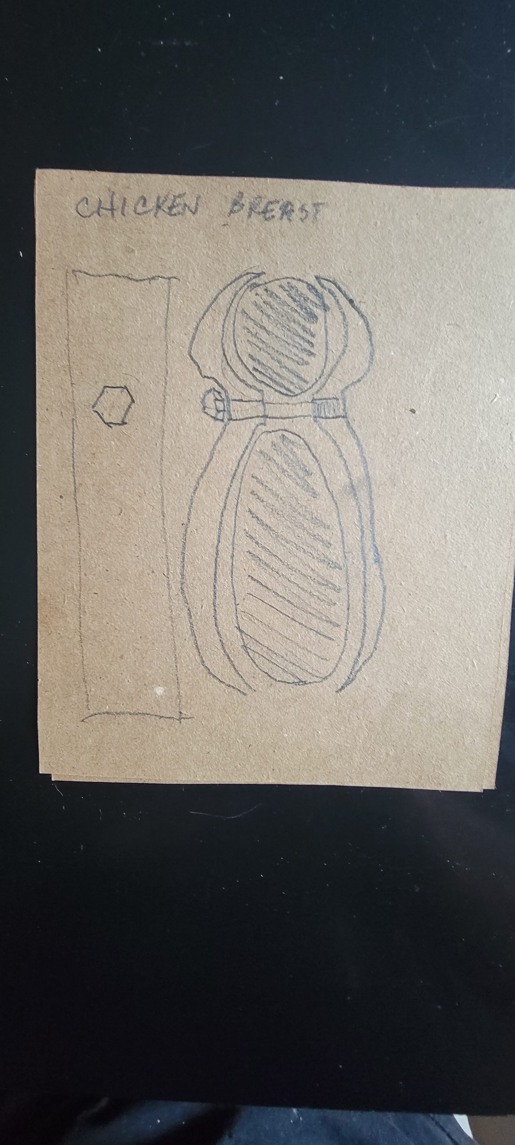
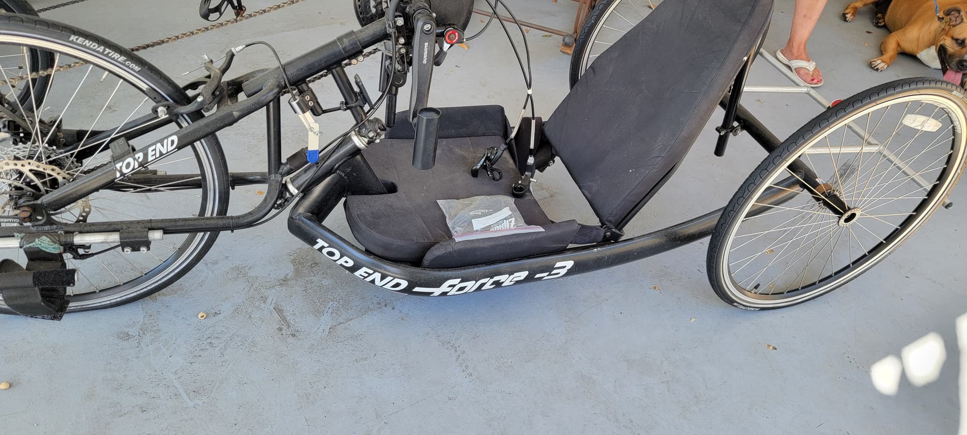
I do have something in mind. The frame is football shaped thin wall aluminum tubing. I trying to design a clamp that uses one bolt to tighten the clamp to the frame. Imagine a clamp that looks like two opposing letter c’s joined in the middle. A bolt between them will tighten the clamp down on the frame and on a piece of tubing at the same time. I drew up a quick end view of the clamp but I have to figure out how to upload it here. It can be designed in anything I just need a one dimension svg. If you look at the frame beside the seat you can get the basic idea I think.
Can you get some accurate dimensions of the frame cross-section? the Diameter of the top bar / tubing, and the size bolt you plan to use. Is there anything else determining the gap? Room for the clamp that attaches the brake & shifter? Also what material for the clamp?
One way to get a good cross section is to mold something that hardens around the frame.
Bondo, Plaster, Wood filler, Clay, Melted wax, fine sawdust mixed with glue…
Cut a couple templates that fit loosely around the frame.
Put a single thin layer of tape (Scotch Tape) around the frame, then a coat of wax on the tape.
Put a bead of your moldable material around the frame & push the templates into it. Let dry, remove, sand the sides perpendicular to the section that was molded from the frame.
Lay them together & take a picture from a point directly above the center of the shape.
Then get a good height & width measurement of the frame using calipers or micrometer.
Thx guys…I’ll measure and get back to you both. I’m not looking for a freebie. More than happy to shoot you guys a few dollars if that is ok on this site. Ill get measurements tomorrow.
Thx I appreciate that but I really dont mind. Im going to wrap a section of the frame in was paper and then with fiberglass cloth and resin. When it gets hard I’ll cut it off. I thank that might get me started.
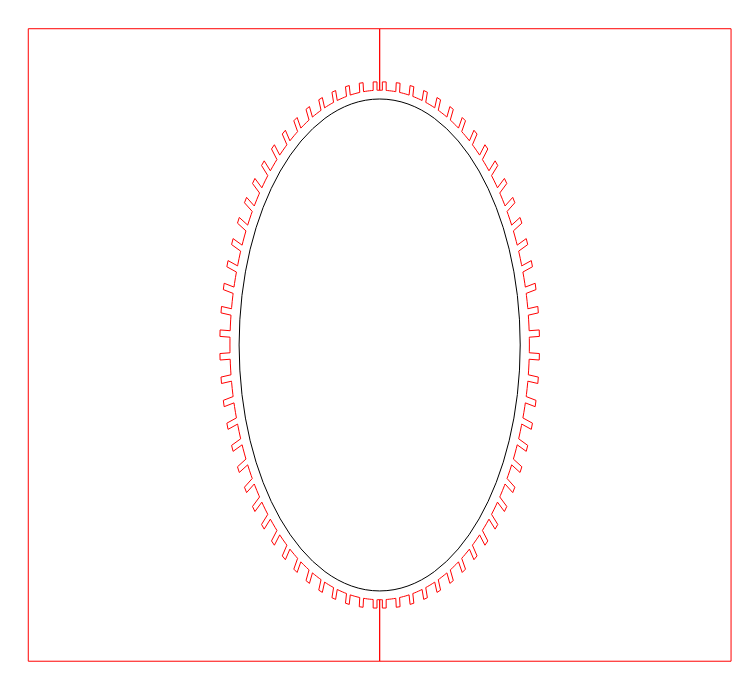
That looks like an almost perfect shape. Im going to make a old of it like you said later today and then try Will’s suggestion for the edit. I dont need too much space between the ellipse and the circle. Just enough to clear the band of the lever clamp. Maybe a quarter inch.
Just throwing this out there, seems doing a mold is overcomplicated and un-neccessary if you have a profile gauge ( or two ) available to you. If not, they can be picked up at HF or big box home center for around $10. This way you can pull the profile in minutes, no mess + you’ll have this handy tool for other projects!
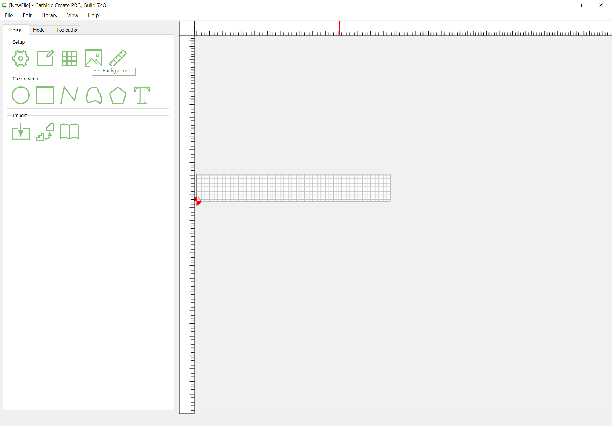
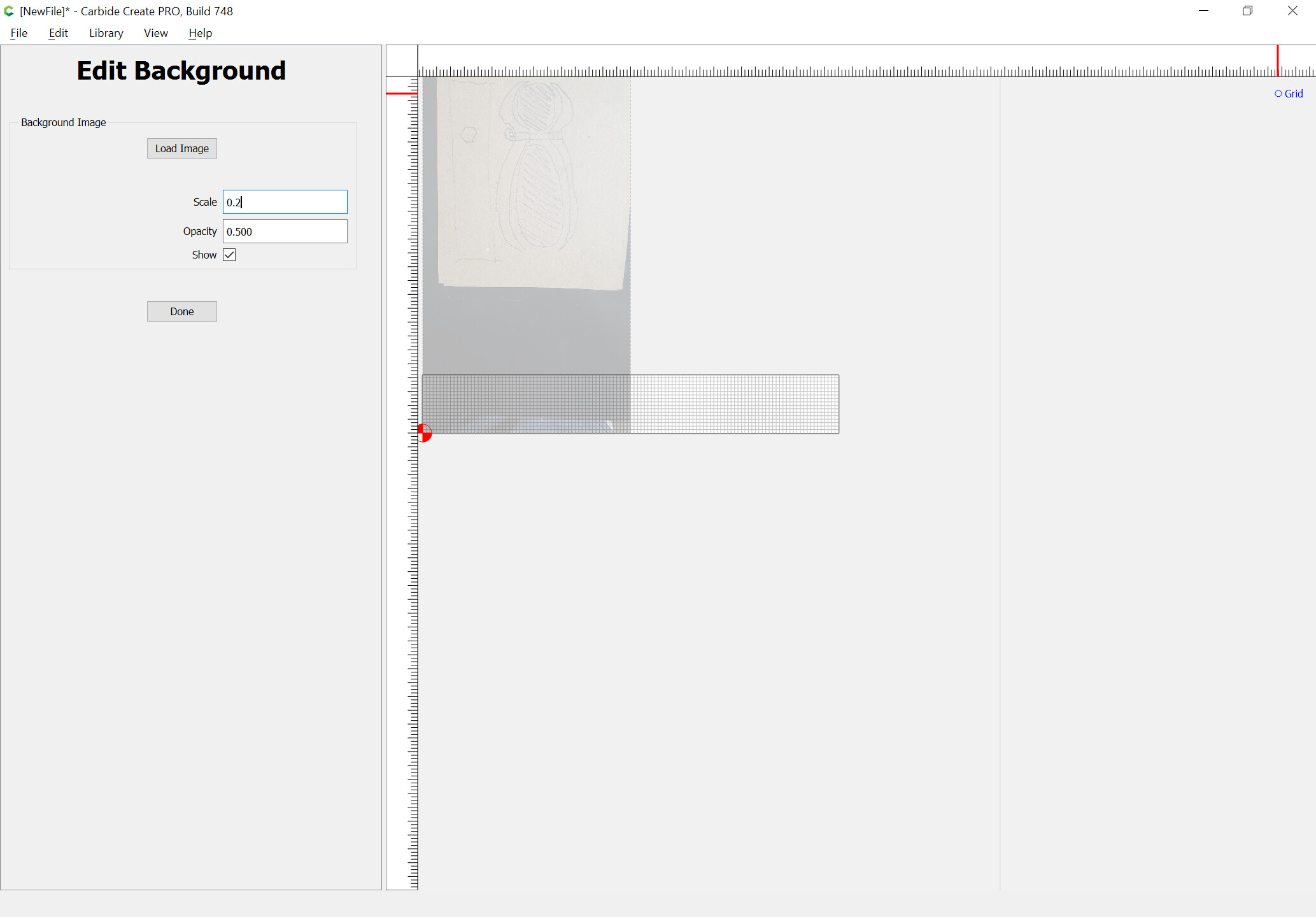
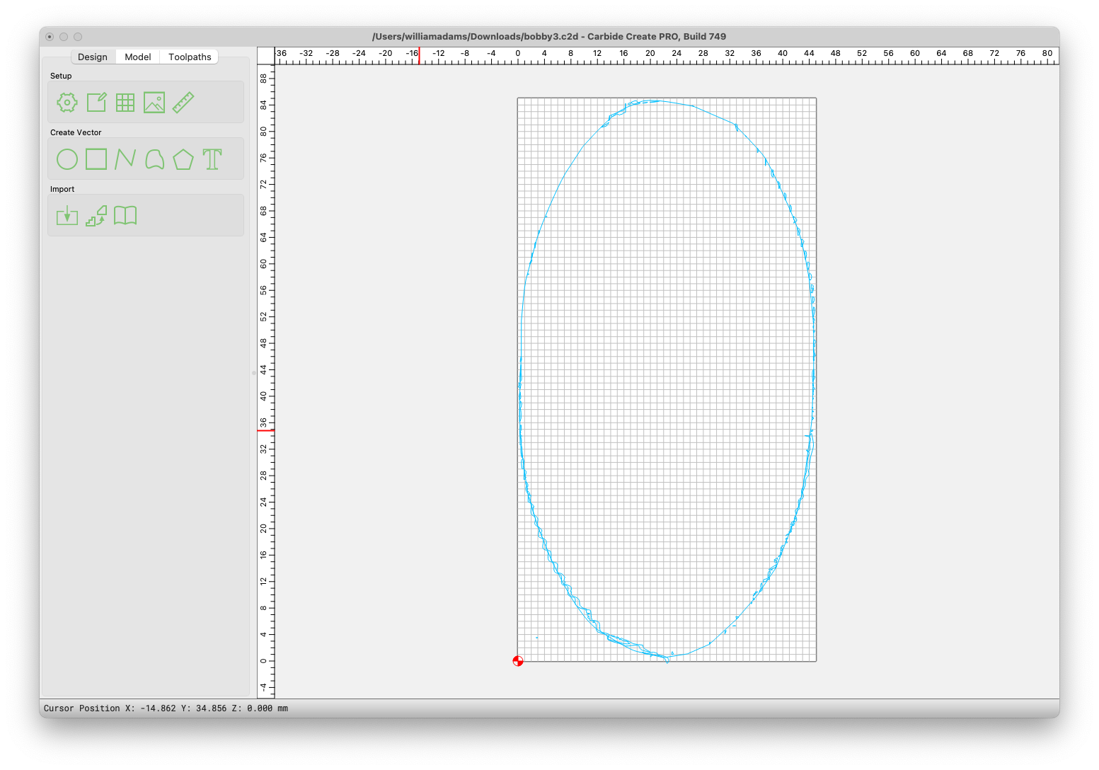
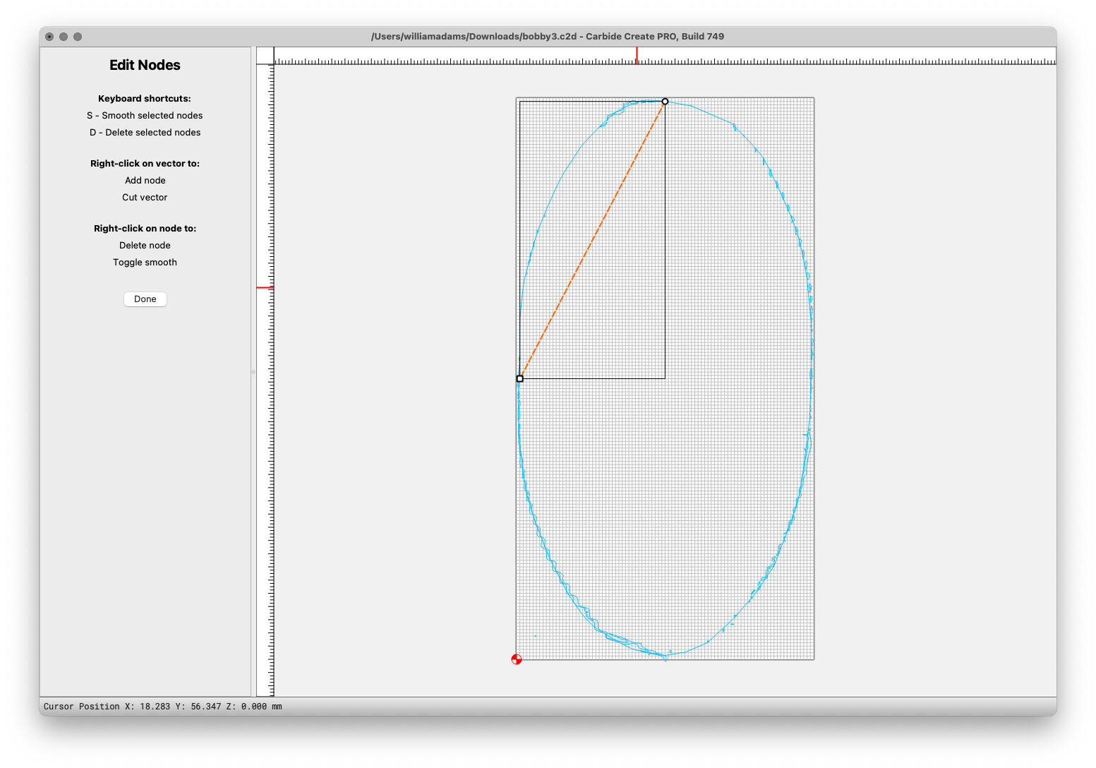
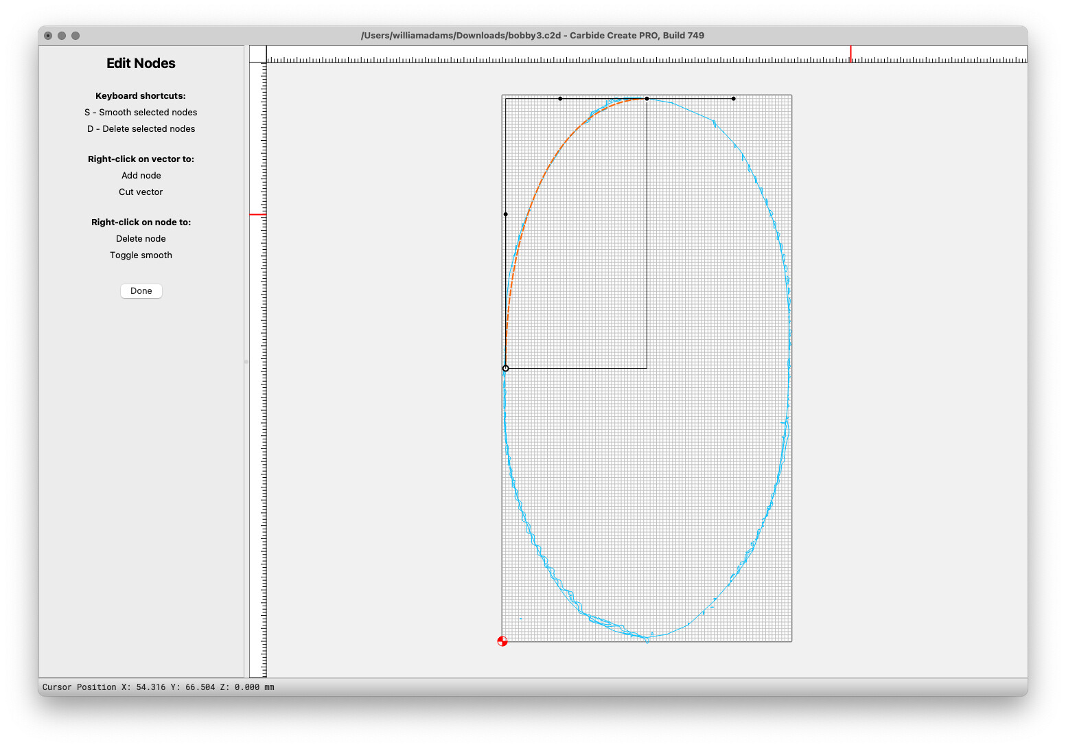
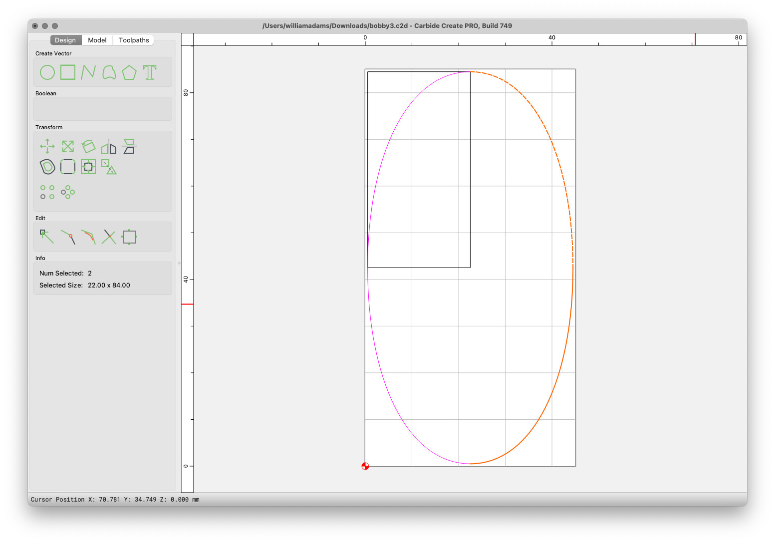
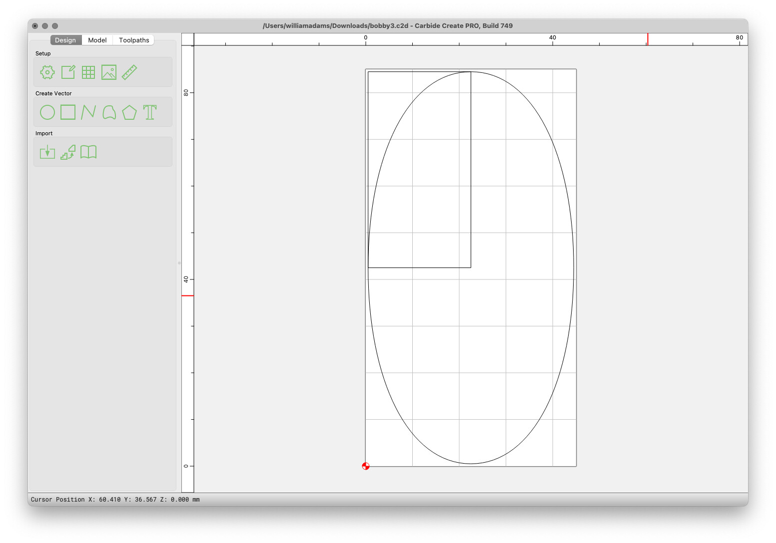
OK…back on this finally. I got a profile gauge and came up with a basic shape. It measures 85mm high by 45mm wide. I took a photo of it and then created a background image in CC7. It set mt stock size to 85mm by 45mm and sized the image to the stock.I then did the trace function. I did not seem to trace that well and I might have to retake photo to get a better trace. Looking Will’s directions it seems it need to just edit nodes until I get it as nice as I can…is this correct?
Well dang…Ive been playing with the thing for hours here. It sure must be nice to know what you are doing. Im impressed. Is there a tutorial on how you did that? To get rid of the original background image do you just delete it or no worry about it?
Drawing w/ Bézier curves is a skill which develops w/ practice. First job out of college was drawing in Adobe Illustrator and Macromedia Freehand 40 hours a week.
See:
for a fun way to practice (though it doesn’t always show the correct method of construction in the interest of gamifying things)
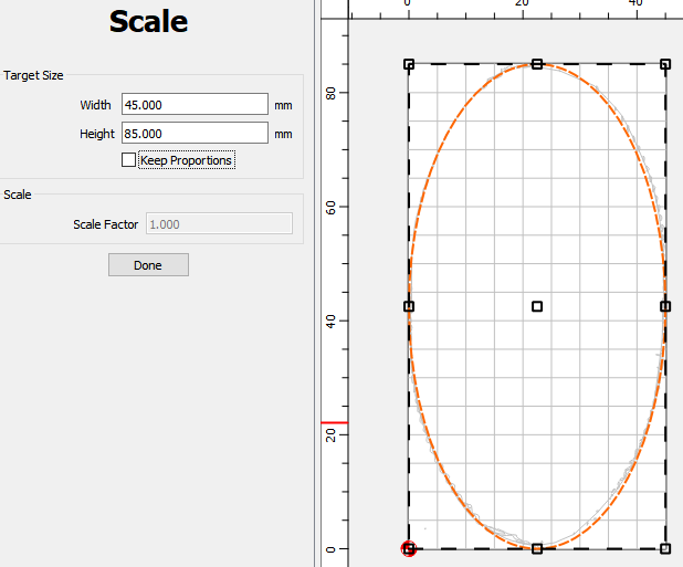
Yes, it was an ellipse. I used the file that Will posted and I had measured a little large. I figured out how to resize it based on the info you posted. I cut a test bracket out of MDF and it fit great. I have some aluminum on order to cut the bracket out of.
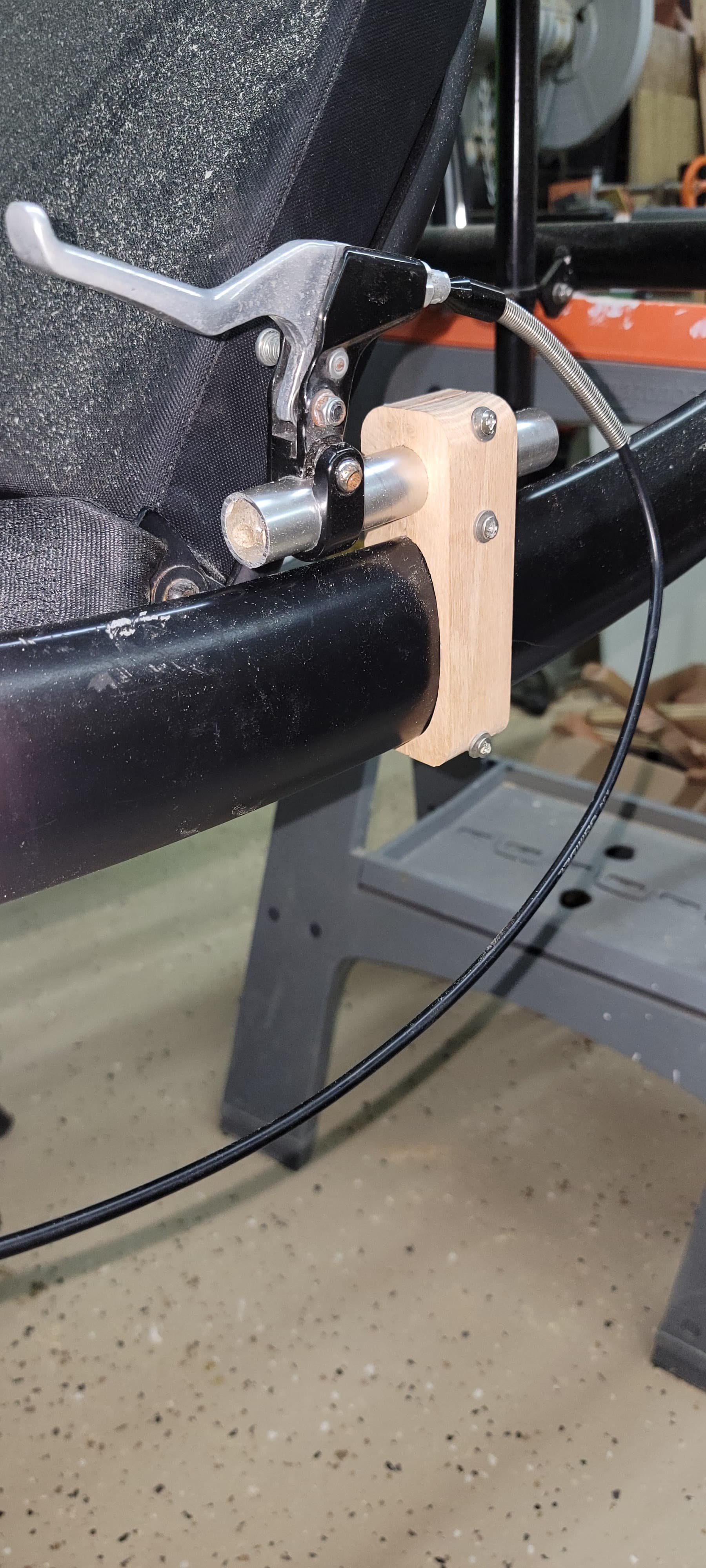
Here is my first attempt done in oak. Im going to try and cut it out of 1.5 inch thick aluminum today. I bought the single flute 1/4 inch bit that CC sells to cut aluminum. Wish me luck.