Did I just unalign my McFly surfacing bit?

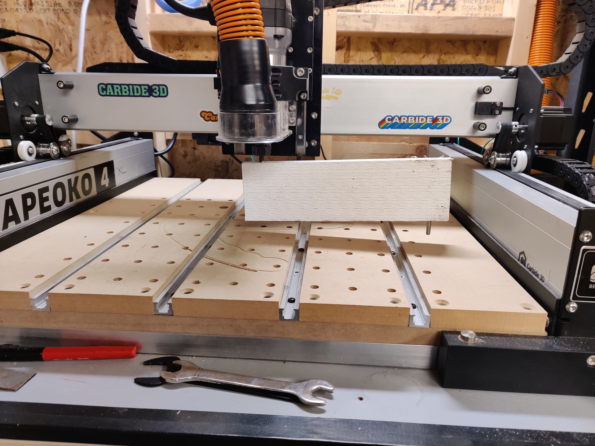
I’m new to owning a Shapeoko 4, and I haven’t used the McFly surfacing bit before. I’m trying to surface a test cheese board type of project in preparation for larger cutting boards. I’ve got it set up in the tool library in Carbide Create (as per Inexperienced with McFly Cutter - #6 by brainy19) and I made a pocket toolpath with a cautious 1mm depth to do an initial surfacing pass.

I zero the bit to the bottom left corner, and I use the XY jog to move the bit over the entire work to make sure I’m not starting too deep. The top of the work is a bit uneven, so I didn’t want to accidentally bite too much wood. I set the zero to be just a paper width above the highest part of the work, it’s fine if it does a 99% air pass, starting slow is fine.

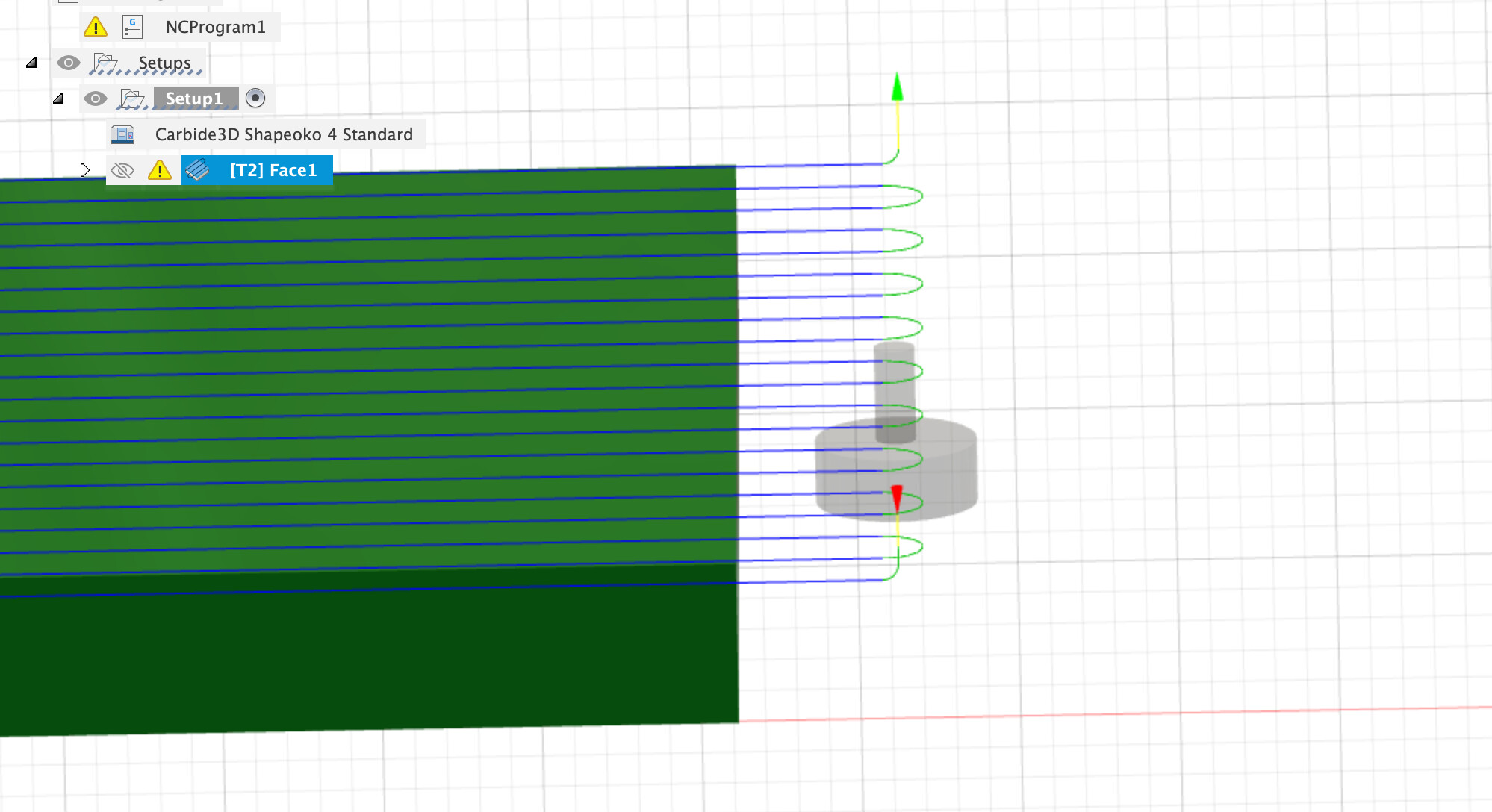
Then I run the job, and this happens:

… the bit beelines for the middle and craters into the work, stalling the router. I hit the pause button immediately and the spindle lifts, and I revisit the settings. The plunge is that visible circle in the middle of the work.

After being unable to find anything strange, I zeroed the Z-axis again and found it was 14mm out. How did that happen? No clue.

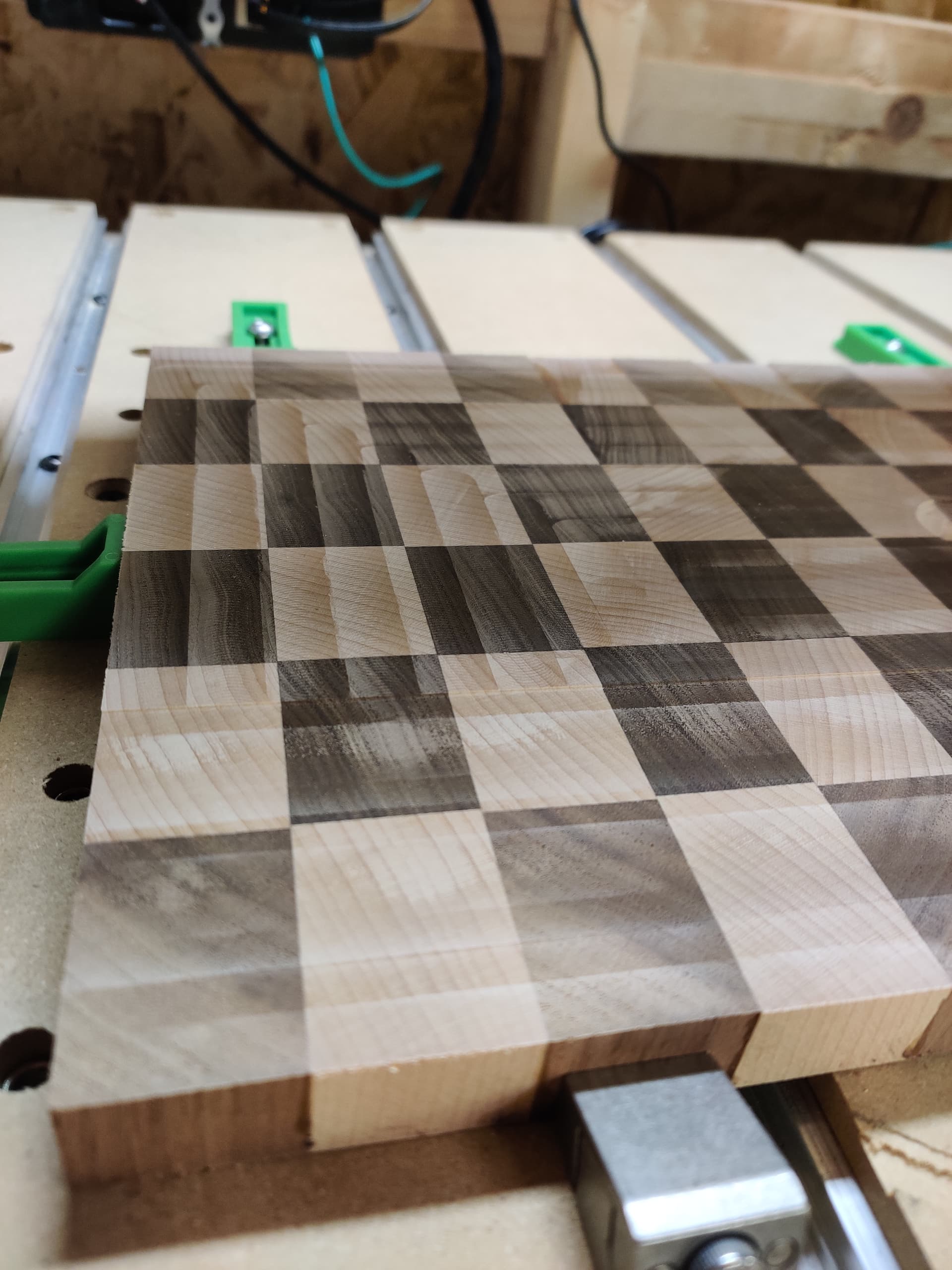
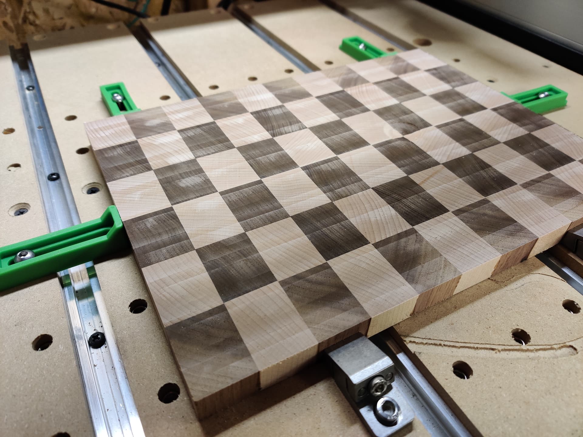
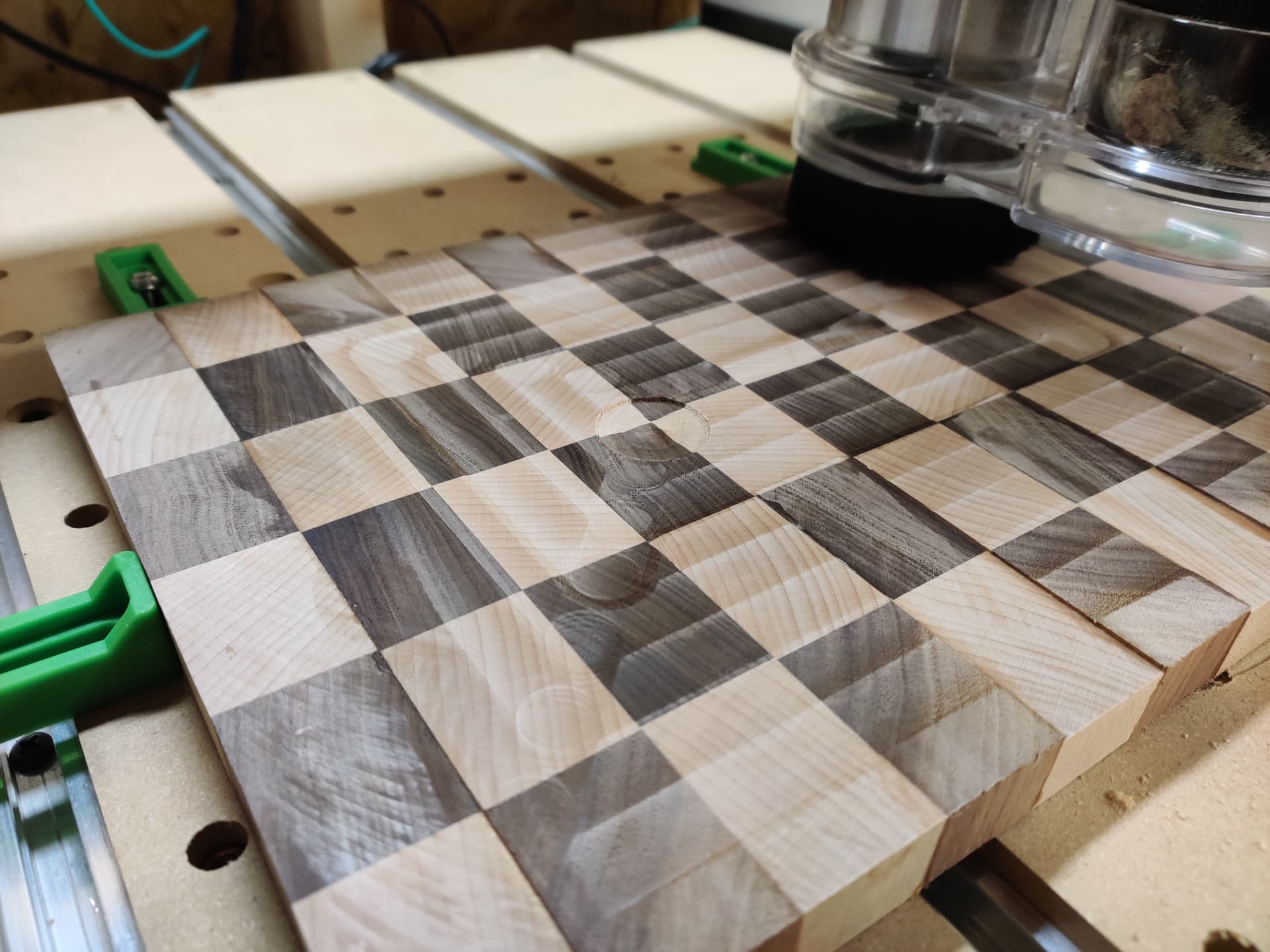
I ran the job again and it worked this time, but the results are a bit surprising. Lots of visible surface defects! In the XY diagonal toward the bottom left you can see the circles as the spindle moves outward, and there are tactile ridges between each pass stepover. There’s also a wide untouched bar in the middle of the piece on the X axis.

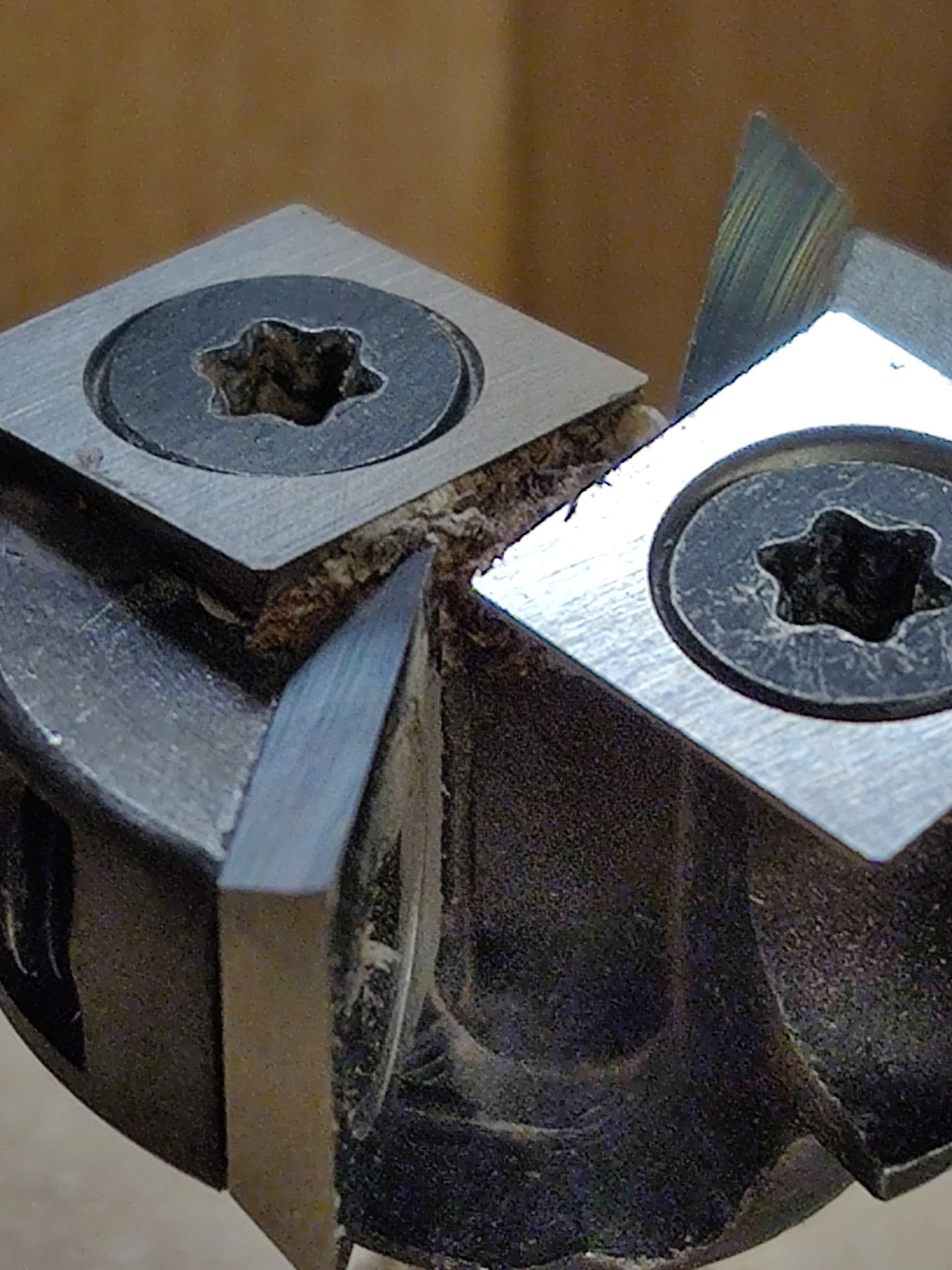
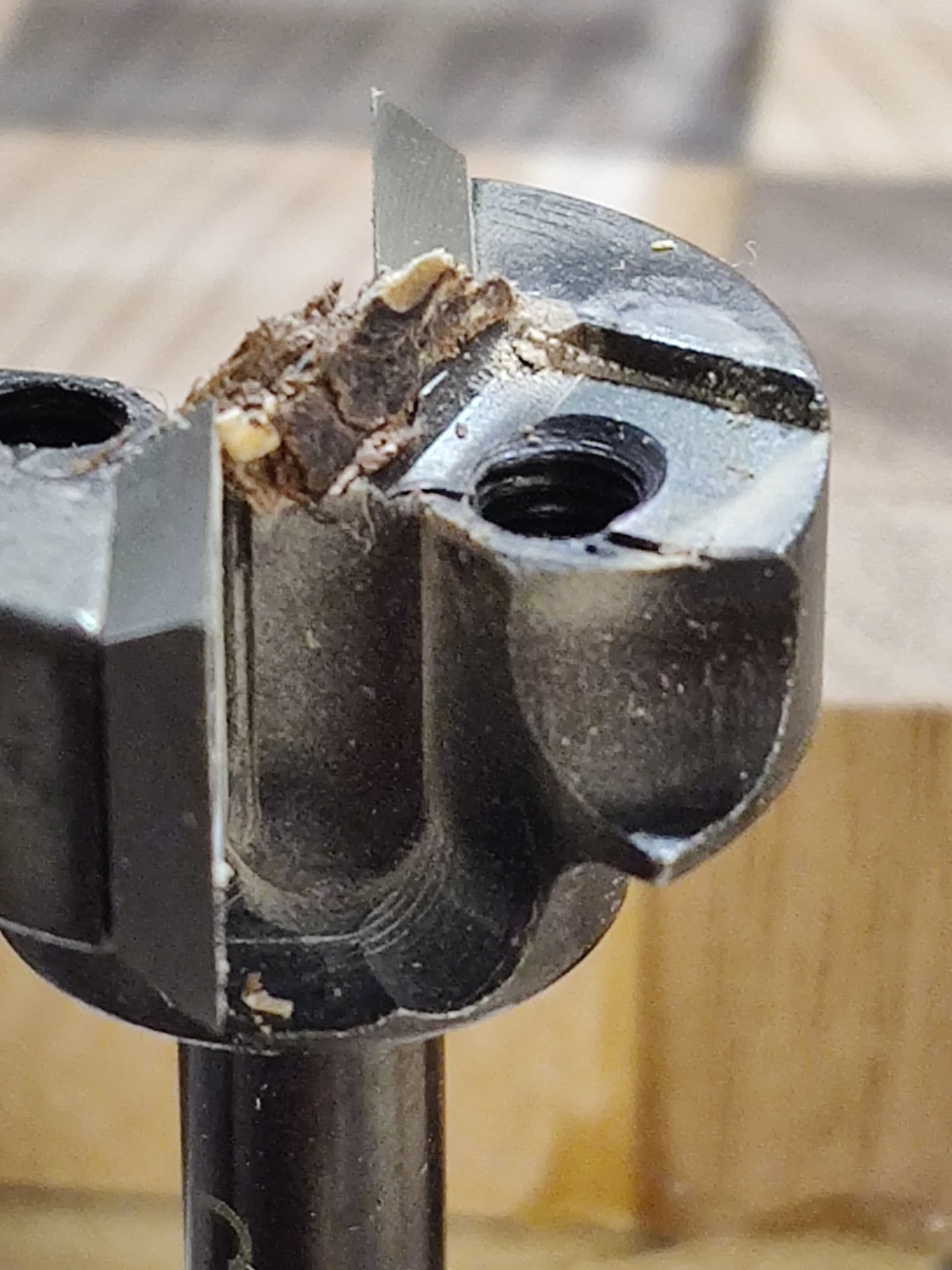
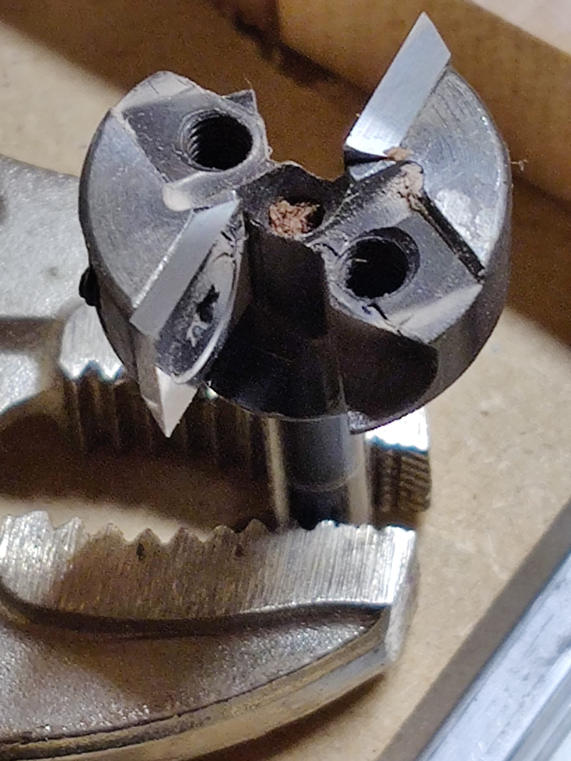
I could probably sand this out, it did mostly flatten the work. Is this a good result though? Did I damage the bit blades when it flew into the work? Is there an alignment guide, or should I try rotating the blades and starting with a new side? Maybe the stepover should be smaller?

I also noticed Y-axis stuttering as the bit moved over the work, maybe the feed rate needs to be reduced. So many variables :confused:

Here’s the nc: 12x9-1mm.nc (1.6 KB) and c2d: 12x9-1mm.c2d (6.0 KB)

Any thoughts? Thanks in advance for your help :slight_smile:

You should expect ‘flat to the touch’ results from surfacing, so there are things to work through - whether it be your processes, zeroing, tramming, missed steps (Y stutter) or random Z-level movements.
For such a modest cut depth, to hear Y stuttering suggests that the Y stepper pulley grub-screws might not be tight or properly aligned on the shaft flats - there are threads on the forum explaining how to do this. A few people have mentioned inconsistent Z depth - I would suggest that you contact support on this one just in case there are teething troubles with the setup/cabling.

4 Likes

Thanks for the ideas @AndyC. Which are the Y stepper pulley grub screws? The only mention of grub screw in https://docs.carbide3d.com/assembly/shapeoko-4/xxl/shapeoko4_xxl_assembly_guide_07-08-21_v1_web.pdf is to hold the router in place.

Actually “pulley set screws”, there is an (old) page about this here:

https://docs.carbide3d.com/shapeoko-faq/shapeoko-3-how-to-check-the-pulley-set-screws/

Worth a check but it’s typically more on the X axis.

Contact support@carbide3d.com in any case

3 Likes

That surface looks wavy, is the router out of tram?

Can you post a picture of your McFly? Are all the inserts tight and aligned?

2 Likes

Looking at that it looks like you need to tram the router - It looks like it’s either nodding forward or backward.

4 Likes

Yeah, it looks like you have a pocketing toolpath and the McFly does not like plunging into stock. It is best if you can use a facing toolpath to make it start at the right z-height outside of the material and enter from the side. Then the toolpath marks you are left with are just straight lines across the material instead of squares and circles.

Also, it does look like you need to tram the spindle a smidge to reduce those defects.

4 Likes

On your first attempt did you disable the BitSetter? I dont have a McFly but use other fly bits that the center of the bit is higher than the blades of the bit. If the BitSetter was used the center void may have set the zero lower than the blades.

2 Likes

I have used my McFly with the bitsetter, with no problems.

3 Likes

All I do for my surfacing bit is hold a thin business card over the bitsetter as the tool is measured. Adds a very minimal amount to the Z but stops the magnet from coming out or the bit not properly aligning with the bitsetter.

1 Like

Wow, thank you everyone for weighing in! Thanks to you I made some good progress today :smiley: 
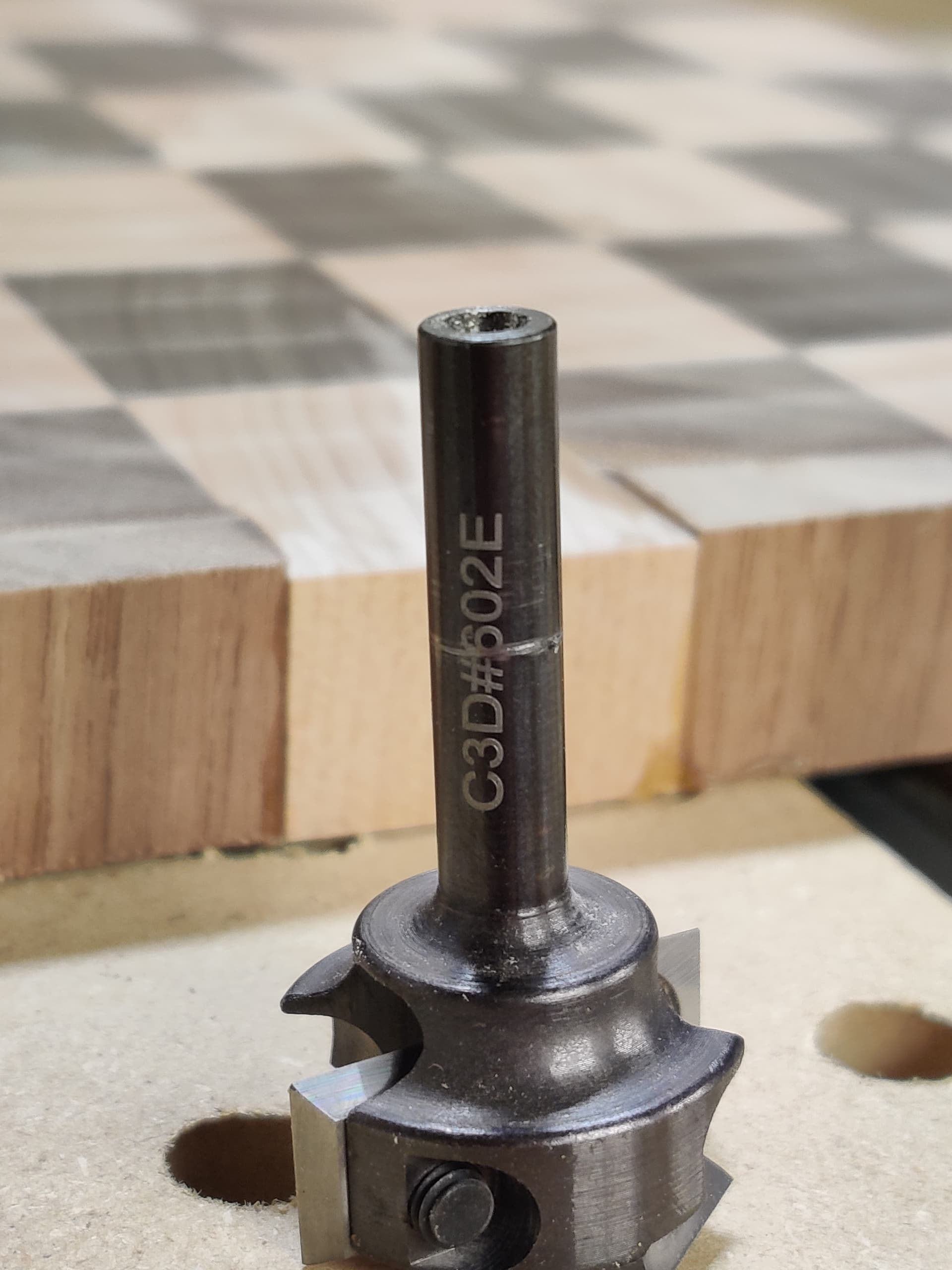
and I have a few photos to share.

First I took a close look at the McFly. It had suffered some pain, the bit twisted so hard in the collet it lathed some metal off the shaft:

The blades look a little uncentered, and there was a bit of dust jammed between them:

I couldn’t scrape it out very well, and after taking the blades off to recenter them it appeared that there was more than just dust…

That’s walnut and maple in there! Got the bits cleaned out:

I’m not sure if there’s damage or not, I didn’t take the blades off at first so I don’t know what “good” looks like.

The next task was to learn how to “tram” the router. New concept, I watched How To Tram Your CNC Router without expensive tools Shapeoko - YouTube and made a similar jig:

It’s far from pretty but it revealed that there was less than 0.5mm variance between all 4 quadrants.

Next I dug into Fusion 360 and figured out how to make a Face path, instead of making a Pocket path in Carbide Create. I’ve only been using Fusion 360 for a few days, my go-to software for 3D printing was Sketchup but it’s past time I learned a more comprehensive application. I watch a few videos and managed to adjust the Pass Extension and Stock Offset so as to start the path far outside of the work:

This is a single pass with conservative parameters. Maybe doing this was overly cautious, but it was a good thing. I zeroed the bit a good 15mm above the work and prepared for an air pass just to see the horizontal path the machine would take, and guess what happened? The machine sent the McFly down to the Bitsetter, positioned XY over the start point, and proceeded to plunge way past zero straight down into what would have been the work again.

I hit the Pause button and stopped the job, then moved the bit back to the supposed Z zero, and this time it was 55mm out. WTF?

So I disabled the Bitsetter. Did another air pass Z-zeroed far above the work, it looked fine. Did another air pass closer to the work, that was also fine. Then I gathered courage and lined up a 0.25mm pass, and it worked.

The McFly started taking out some of the ridges out of the previous experiment. It looked much better and felt pretty flat! I lined up a second 0.5mm pass and it got most of the previous artifacts out of the surface and it looks much better:

The board feels very flat (with the exception of the crater) and I think the lines will sand out.

In conclusion I think there might be something up with the Bitsetter process. I noticed it went too deep once when I was plunging the inset holes on my wasteboard, but didn’t think much of it and re-zeroed. The McFly doesn’t have much vertical variance on the blades, certainly not 55mm worth.

Anyway, thank you all again, I’ve learned a lot over the last 24h.

5 Likes

Hi @emc,

There are two traps with the BitSetter process resulting in 99% of the reported issues:

  • BitSetter works by automatically adjusting the set Z0 based on the difference between the bitsetter measurement done at the start of the job, and whatever was the previous bitsetter measurement (typically, the one from the initialization process). This works fine if you only ever change the tool either when prompted OR by explicitly using the change tool button in CM. If at any point you swap the tool without telling CM, then it will use an old/obsolete Z reference (corresponding to the previous tool that was probed), and it will throw off the Z.
  • Enabling or disabling the BitSetter and not resetting the zeroes: since the Z0 management is very different depending on whether BitSetter is involved or not, if you toggle the BitSetter enable checkbox, you MUST redo your zeroes afterwards. With a 55mm error in your case, I would tend to think it might be that.
5 Likes

That’s a great explanation, thanks @Julien. I’ve been changing bits and zeroes a lot recently, I’ll pay more attention to these conditions.

1 Like

Yep, I’ve done #1 that Julien mentioned before when I first got one a few times. I needed to learn that I can only change endmills when the machine says I can or if I initiate a tool change.

1 Like

You also might want to give a “climb only” face cut to see if you can minimize the tooling marks

1 Like

@Vince.Fab I did see that option in Fusion! What’s the advantage, that the cutting edge is always on the same side?

Also do you have any suggestions for stepover values? Right now I have it set to 50% of the cutter width which works out to 12.7mm, I’m wondering if a wider path would result in fewer tool marks.

when your machine switches from climb to a conventional cut, the forces and deflection directions change. Climb only should be more consistent and that should mean a better surface finish. For stepover, Ive been told to stay away from 50% and usually tend to run from 67-95% for a smoother cut force profile. Keep in mind that the more tram error you have, the more it will show in larger stepovers

5 Likes

Huh, I’m curious about this. I’ve run 30% stepover when I was trying to be careful. Are you suggesting to stay in the 67-95% stepover range and just control the forces using the depth of cut instead?

This topic was automatically closed after 30 days. New replies are no longer allowed.