As has been discussed here, I’ve never found a traditional 3D CAD tool which was a good fit for me (we will spare folks the littered list of losses).
However, v29 was recently announced and has a muchly more consistent UI, such that:
seems approachable, so we will try to walk through it.
First, get a copy of Alibre Atom 3D (or other program variation — I will be using Design, but I doubt that I will avail myself of any features outside those basics which the entry-level exemplar includes) — bundled w/ a Nomad (tiling this design will be left as an exercise for the reader), it is available for purchase at:
or a trial may be downloaded from:
First, one launches the program:
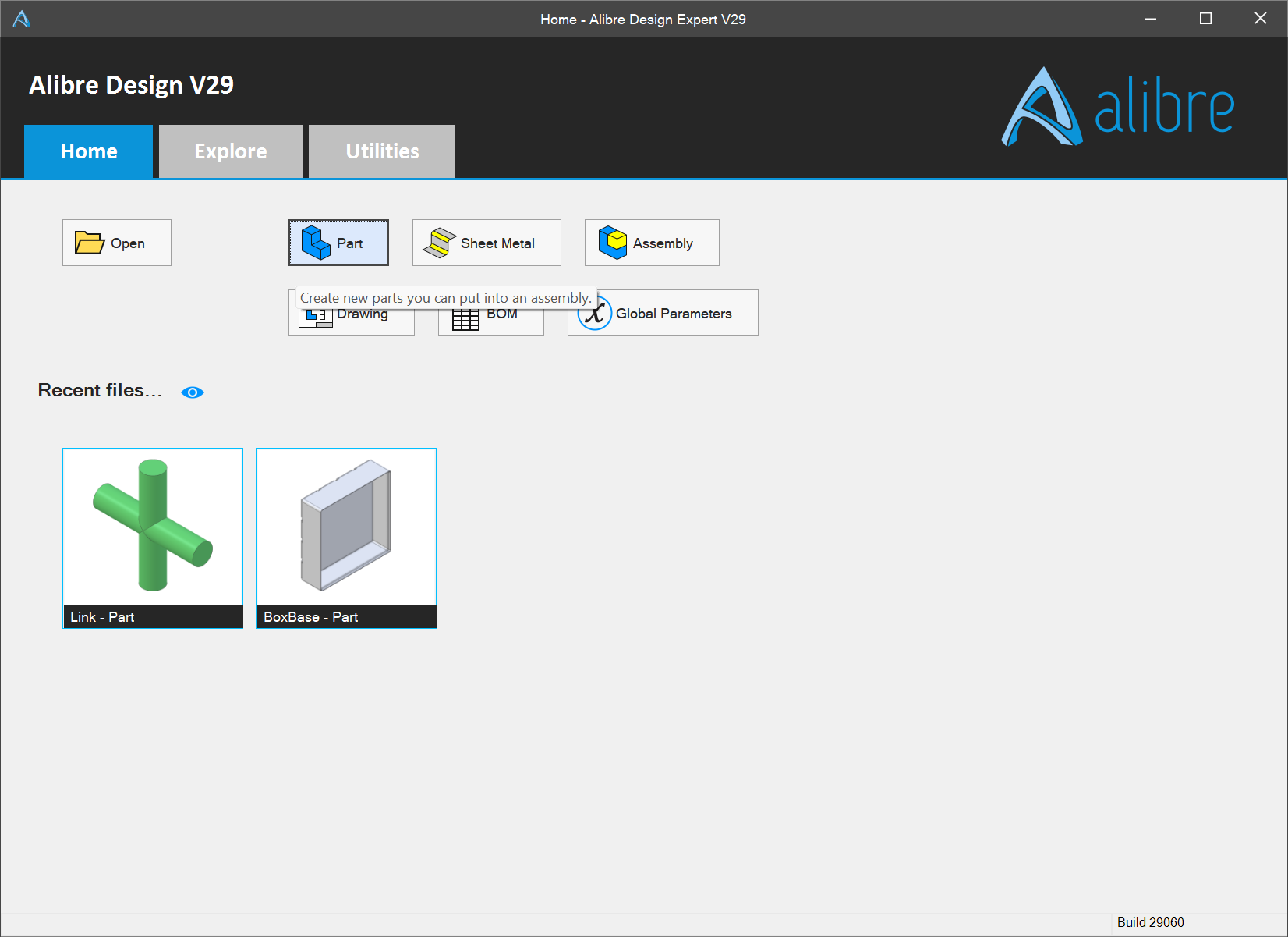
We will be making a Part at first, so that is selected:
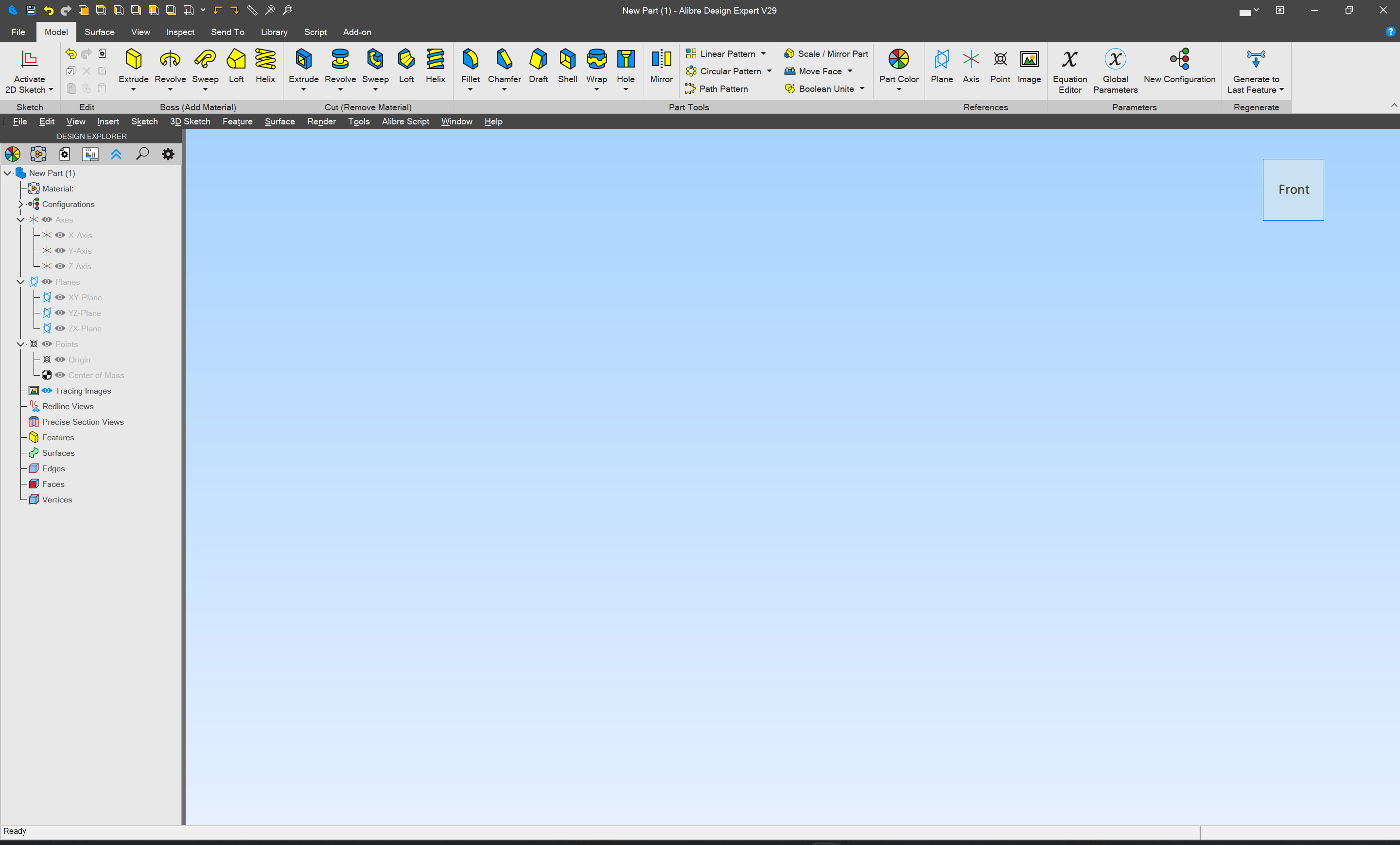
The first consideration is what view is being used — since we wish to draw a side view, rotating the proxy cube in the upper right corner seems a good first step:


a second point and click:

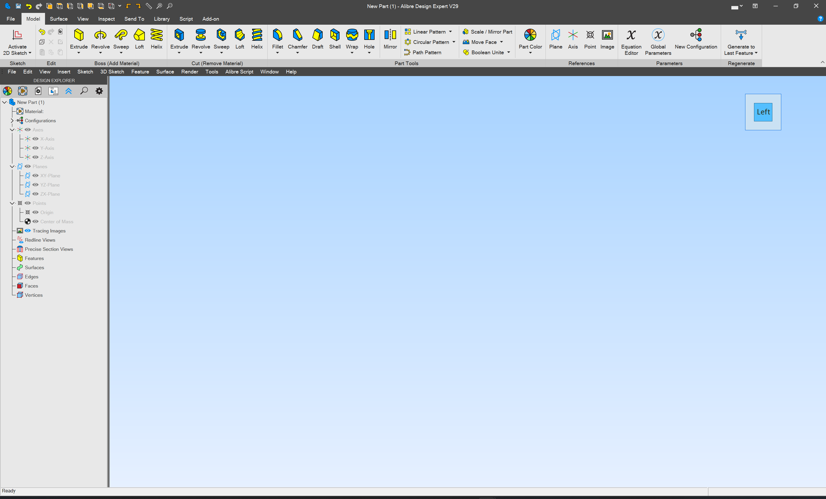
has brought this around to the left, but no change in the balance of the UI.
Currently, the view is 3D, but we wish to draw in 2D — the Design Explorer at the left should allow one full control over, and navigation of the design process and the part and its elements, so we take note that there are 3 planes listed:
- XY
- YZ
- ZX
which presumably are used for 2D drawing — which should be active is dictated somewhat counter-intuitively by which plane is not specified, so:
- XY == overhead/underside view (the observer is shifted along the Z-axis plane)
- YZ == left/right view (the observer has moved along the X-axis plane)
- ZX == front/back view (the observer has moved along the Y-axis plane)
since we want to work on a side view we choose the YZ plane:
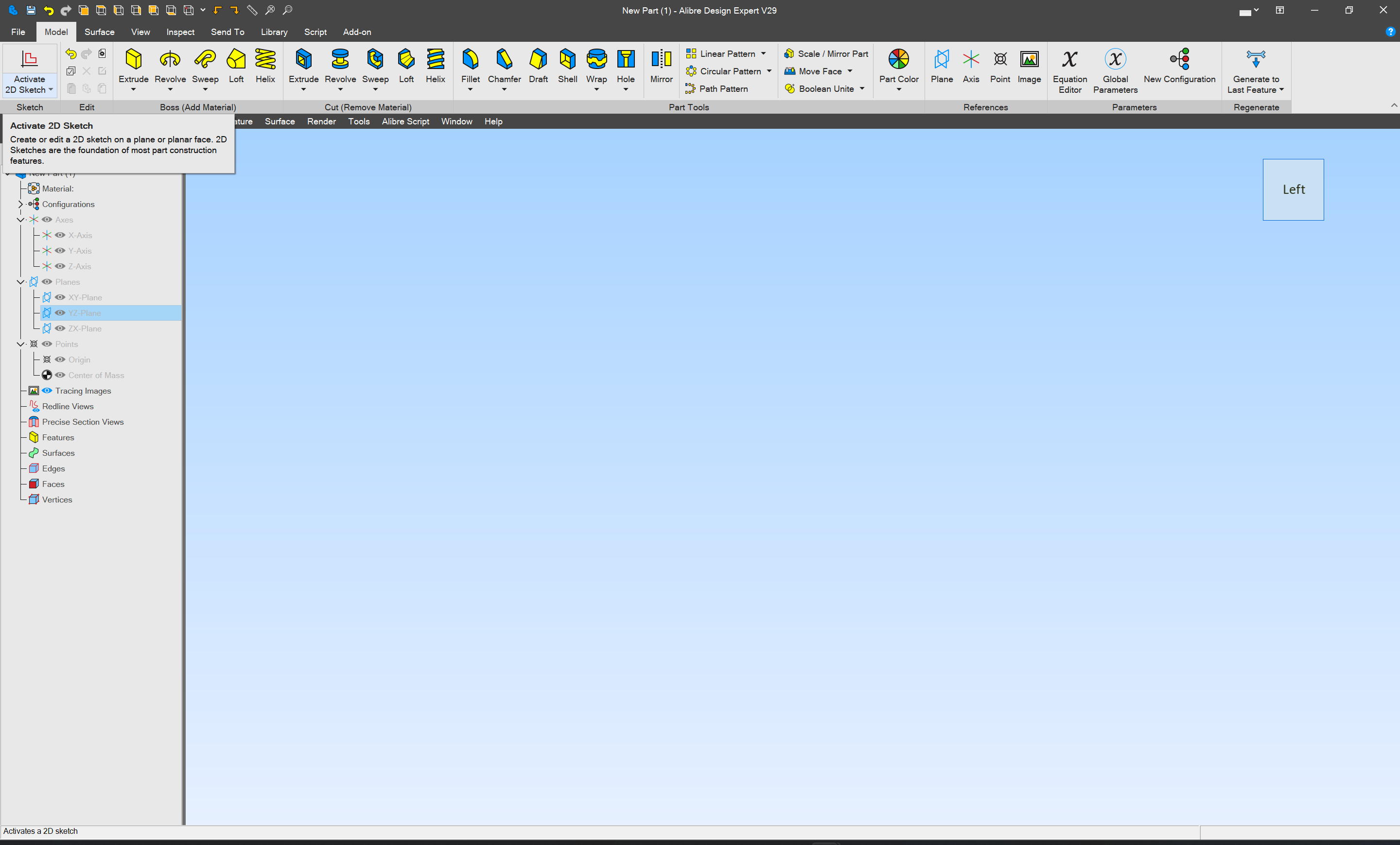
and click on “Activate 2D Sketch” in the upper left corner:
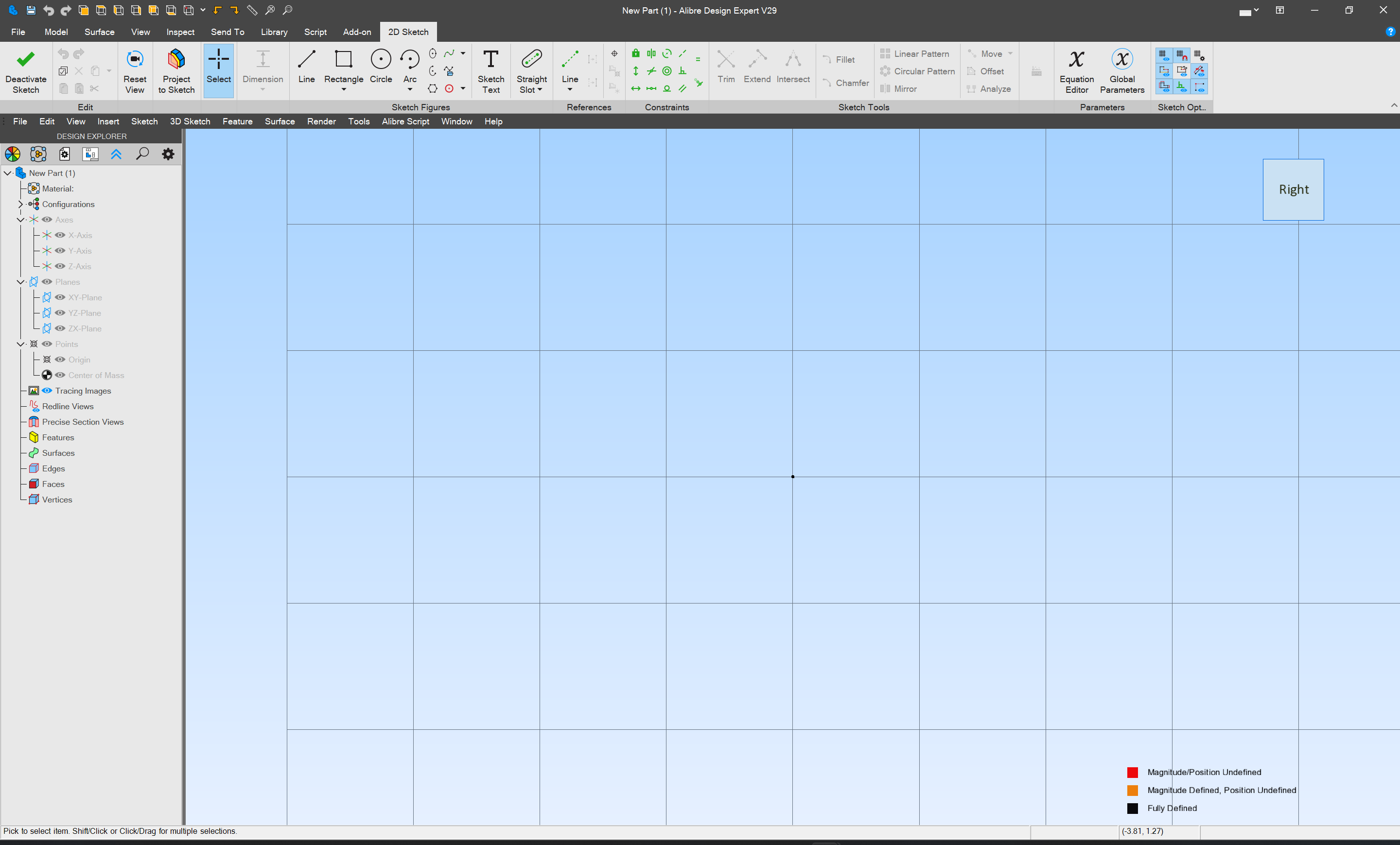
which brings up a drawing view. We will start by drawing what is usually the right-hand side of such, and typically uses a hole so as to capture weapons when secured, so we select the Circle tool:
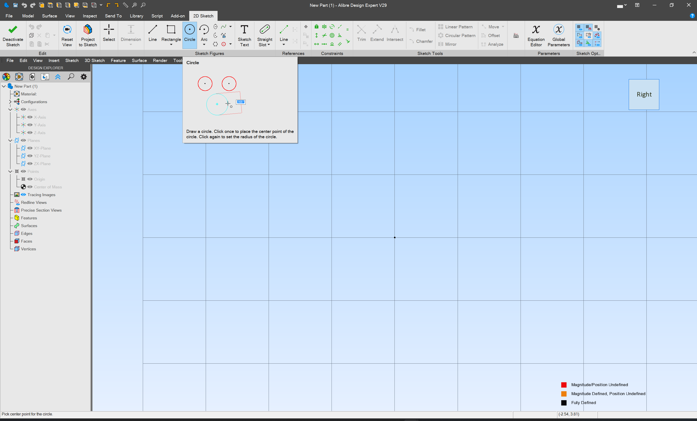
move to where the circle’s center/origin should be:

click
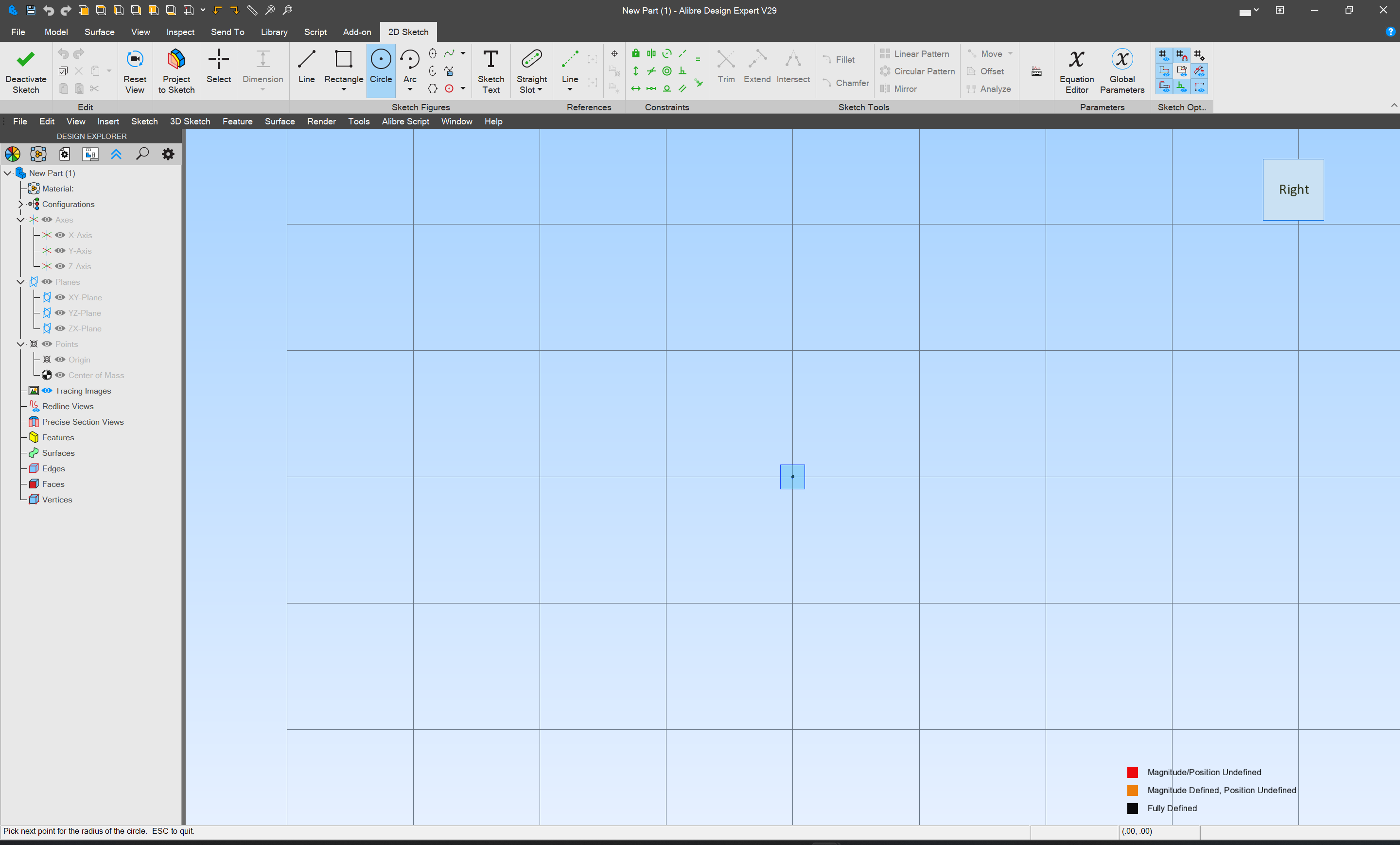
move off to the side:
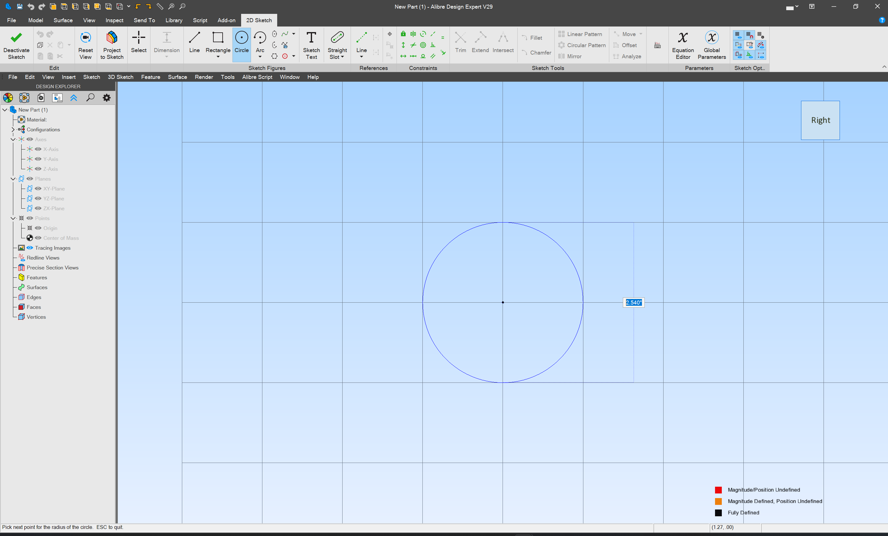
and click again (I believe one could enter a dimension during this process, but we will be a bit more deliberate)
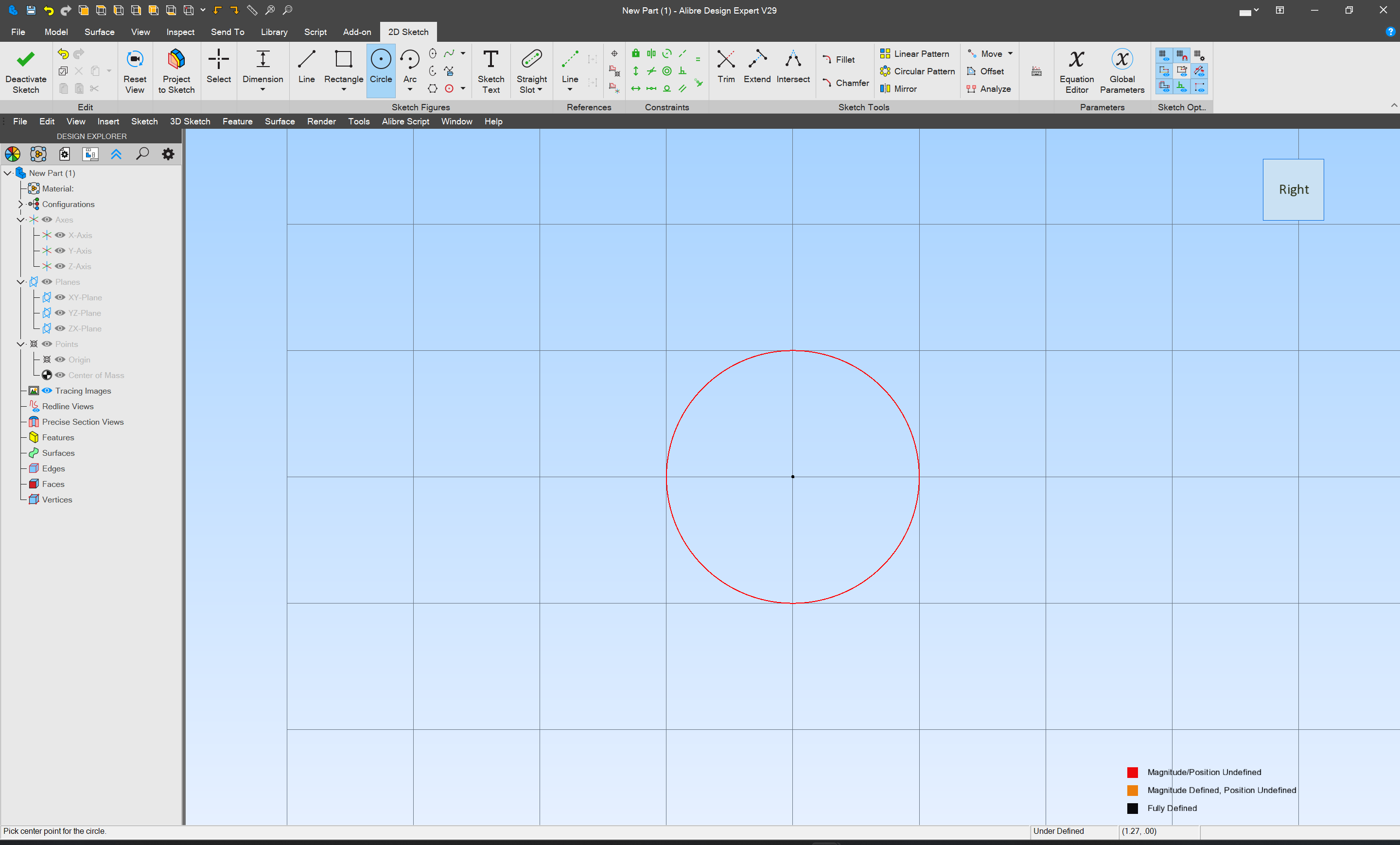
Another approach for setting the size would be the “Dimension” tool:
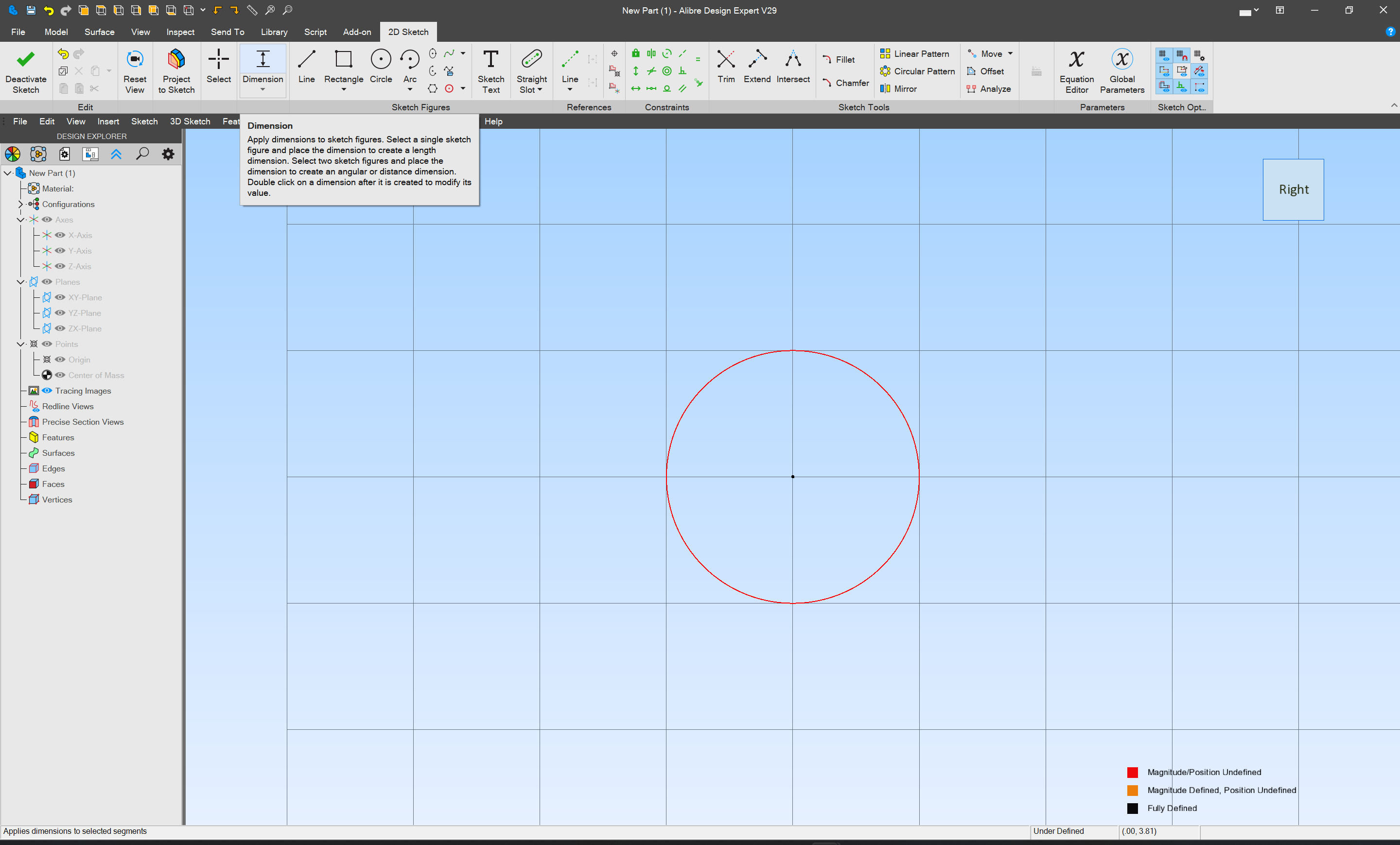
but it indicates that first the object must be selected, so we switch to the “Select” tool:
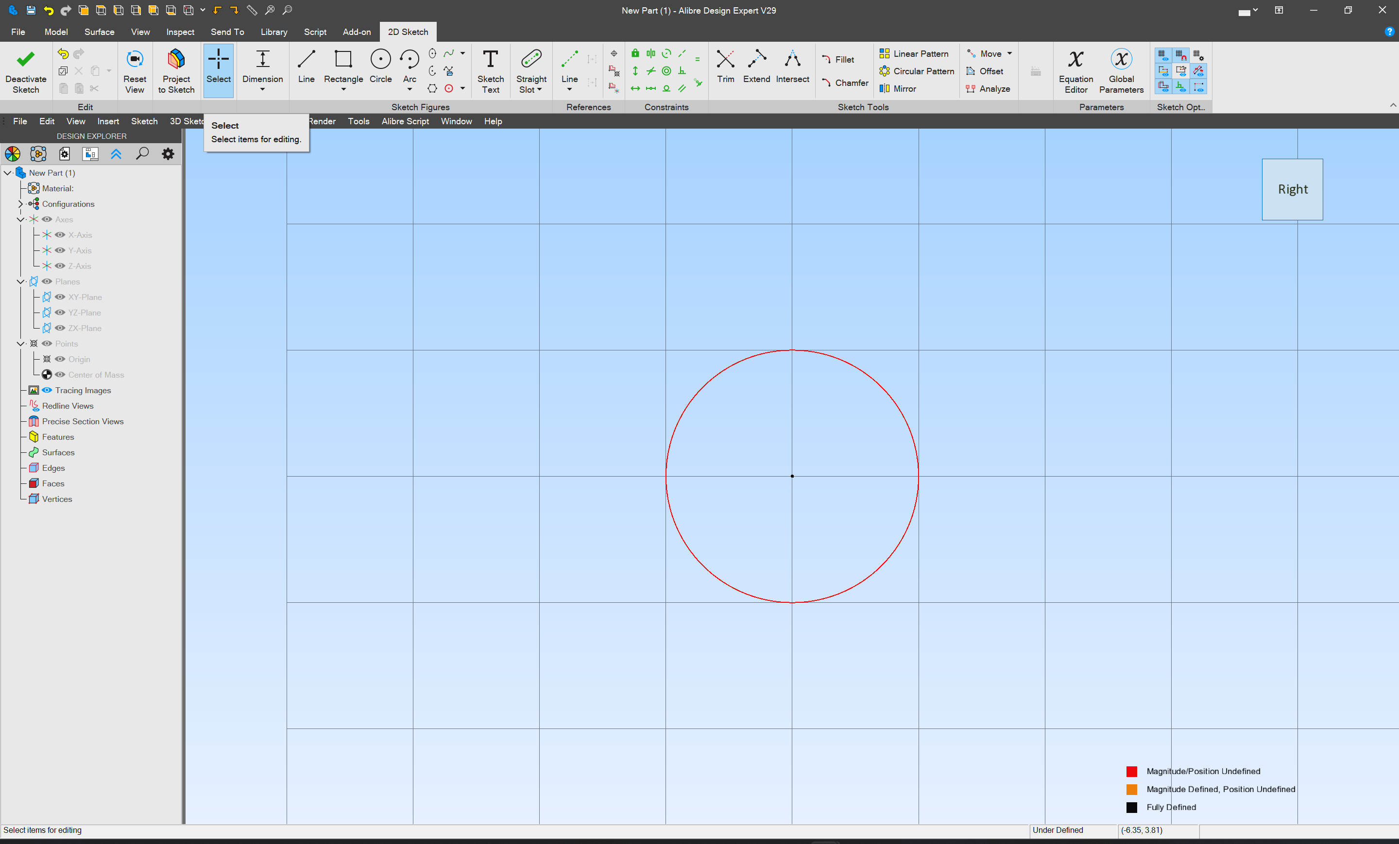
then Dimension:
and click:

and move off to the side a bit:

and click again:
![]()
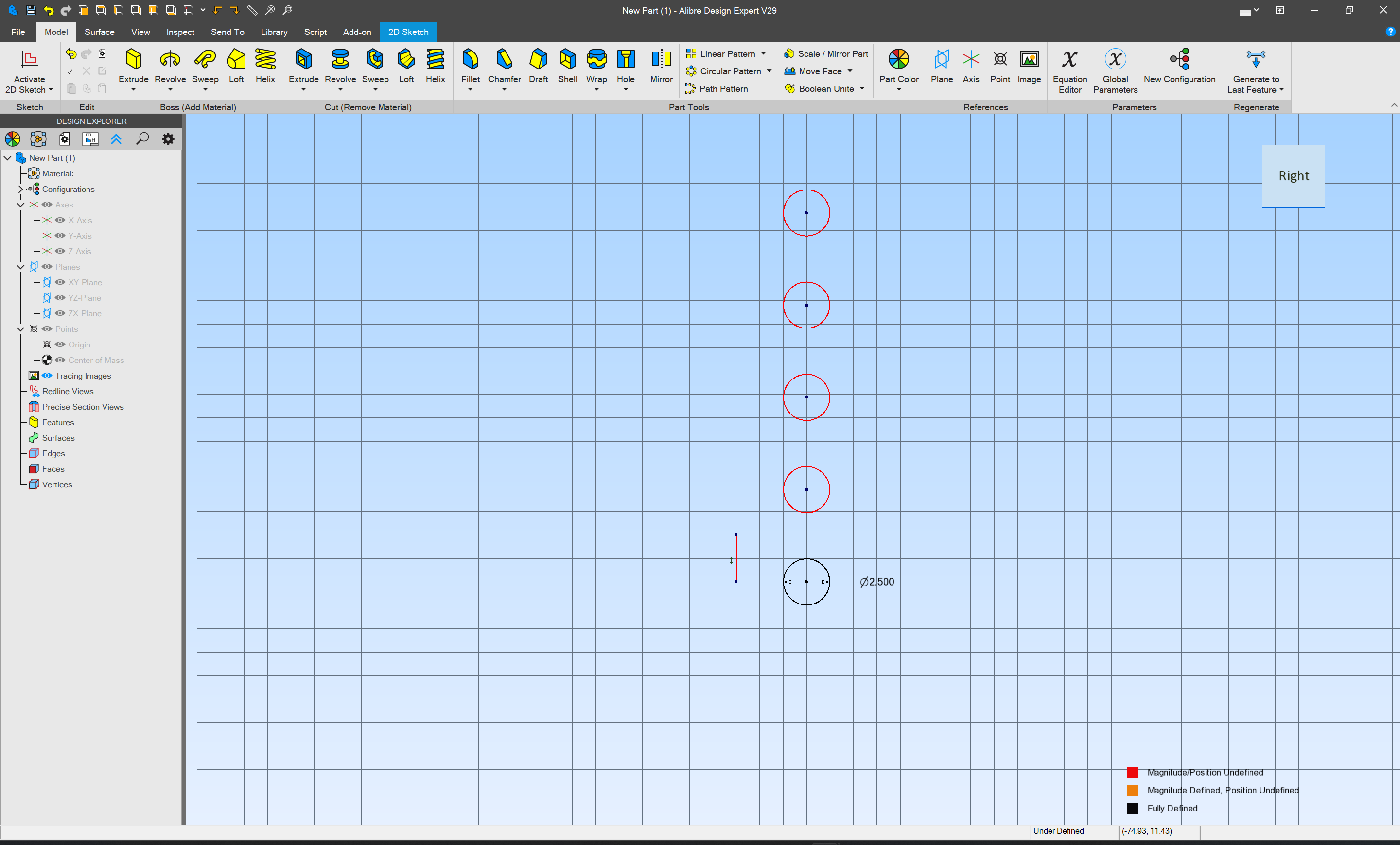
where we enter the desired diameter:
![]()
and tap Enter

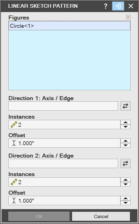
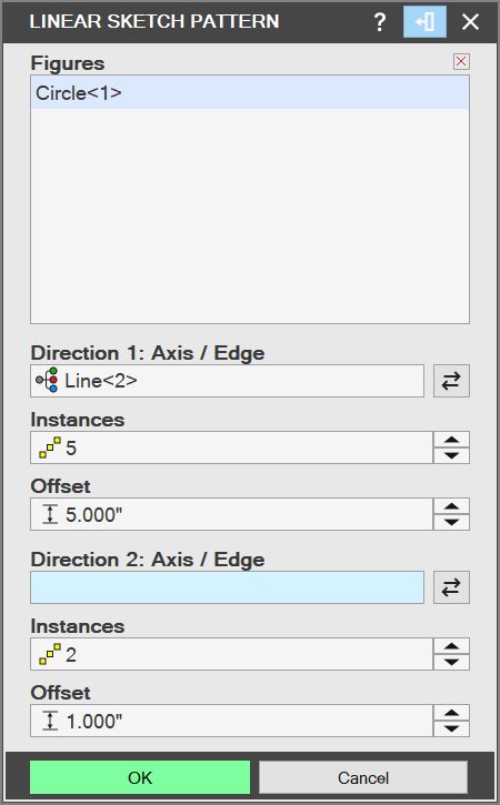
next, we figure out how to draw an array…