I’m working on making some bolt-on parts for the back of my HDZ. Are there are any drawings running around for the tapped hole pattern on the back of the HDZ, or am I going to need to measure everything myself?
Seems like the kind of thing that should already exist, but I’m struggling to find it. Thanks!
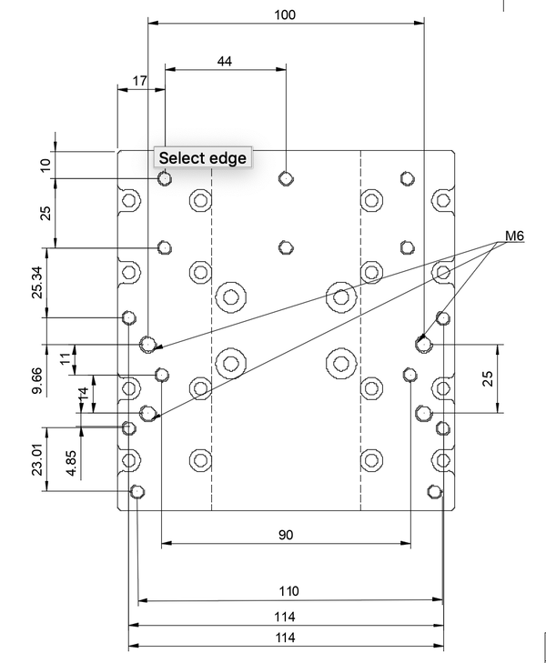
The plans are not available, (and @Luke can probably confirm whether they would ever be, this is not an open hardware item as far as I am aware). For what it’s worth, I did a (very incomplete) Fusion360 sketch of the back of the HDZ based on my own measurements and posted the design file in this thread.
I was only interested in two of the tapped holes near the top, and the location of the two holes at the bottom that hold the bottom plate. My frame thingy designed to these dimensions was assembled with no issues, but the dimensions may still be slightly off, since I used generous tolerances on counterbores, and parts made of (3D-printed) plastics to not have to worry about that.
Luke actually posted a sketch of the HDZ’s design on beavercnc.co.uk at the beginning of the year when he was still actively developing his own products. I’m not sure however if it changed since C3d took over the production
by the way, as it is not completely off topic to this thread, how do you reliably/precisely measure distance between holes? I must be missing a simple trick or tool, I always found this hard to do (accurately that is). Measuring edge to edge and then measuring diameter can be done, but the edge to edge measurement is not easy with regular caliper jaws.
@Julien I’m having the same problem and so does everybody else as I believe. When I’m reverse engineering parts that are made by large companies I like to believe that the designers are using their common sense and mostly DON’T use fractions or at least in some reasonable increments. If that’s not the case then it’s mostly try an error. Depending on how critical the dimensions have to be I might slightly oversize the holes and usually get them right in the second go.
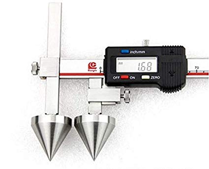
What I probably should do is get a ‘vernier caliper centerlines’. They sell them either as an attachment to the calipers or as a completely separate calipers. That’s the easiest way to get the spacing right.
thanks. I remember searching for something similar, though probably not with the right words, and at the time the ones I found were crazy expensive (which is to be expected as I guess these are niche models)
If you have examples of sub-50$ solutions I would be interested, if not I’ll stick to eyeballing using a regular caliper
Here is what I have used, it is not perfect but pretty close. When the hole is threaded, I put a cap screw in the hole all the way to the end. I then use calipers to measure the distance by placing the caliper over the two cap screws and subtracting the size of a cap screw. This gives me the distance between the center of the holes. If the screws are of different size, you would have to add the size of the heads and divide by 2.
I have used all of the above tricks to get close, especially hoping that the dimensions are nice numbers (this is where a set of calipers that will show you fractional inches can be handy as well). Taking a picture of the part and importing that onto your canvas in fusion can help sort things out, but often doesn’t help with accurate measurements.
If I were smart I would have taken these pictures and measurements last week before I mounted my HDZ :).
Just a little bit more about what I’m doing - I’m trying to design a different dust boot setup that doesn’t sacrifice any X travel with the HDZ and gets the hose supported closer to the rail to minimize any deflection it could cause.
It kind of surprises me the hole pattern isn’t published by Carbide3d. I’m not looking for any sort of “open hardware” or a full model, but when a company is built around people who tinker and mod, it’d sure be handy to have the basic interface documented to encourage more tinkering and modding.
I’m on the same boat, hence this ongoing attempt (first at a frame/plate/support that does not exceed the HDZ width, and then at a dust shoe that mounts onto that). I’m in the process of designing a version2 that is less ugly / more practical. Let us know about your efforts in that endeavour !
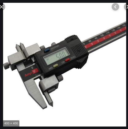
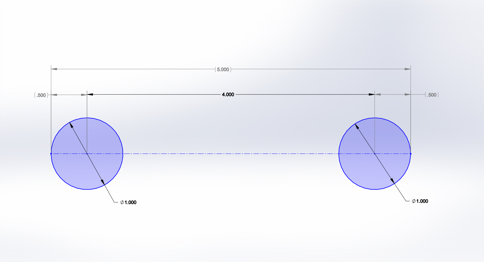
@Julien Most calipers have a reference zero function. Assuming the diameter of both holes are equal, you can measure the diameter first, zero the calipers at that measurement, then measure the maximum distance between the edges of the holes. Effectively you’re subtracting out the additional 2*radius up front, which results in a center-to-center measurement. Hopefully that helps.