Has anyone made the left edge guide that Kevin makes …where do set your x,y,z to make the cut on it once it’s bolted down to the table to even it out ?
We have some edge guides in the Carbide 3D Print Library:
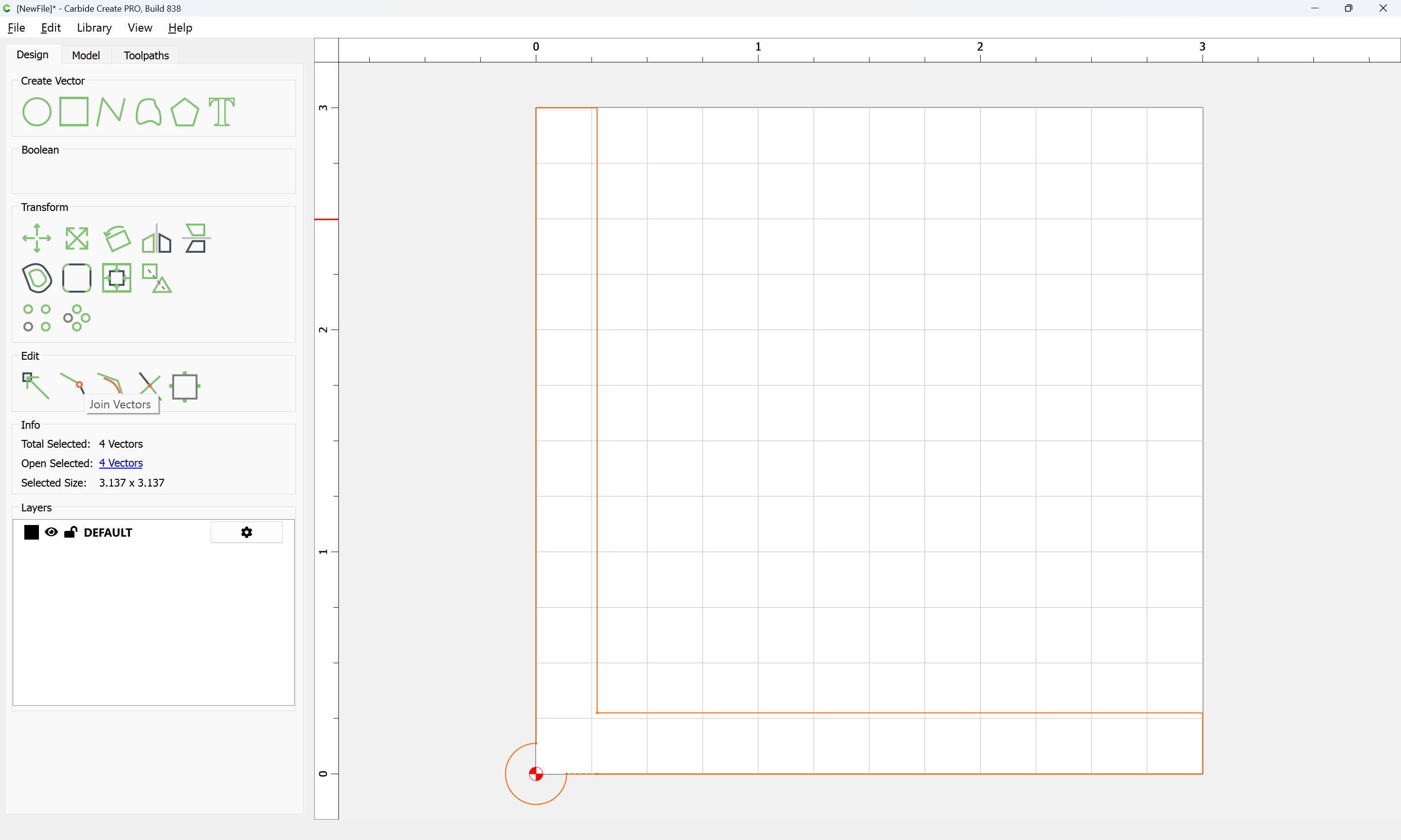
Where the origin would be set would depend on the toolpath being used, but I’d suggest one which would allow the origin of the file to match where one actually wants to set it, so something like:
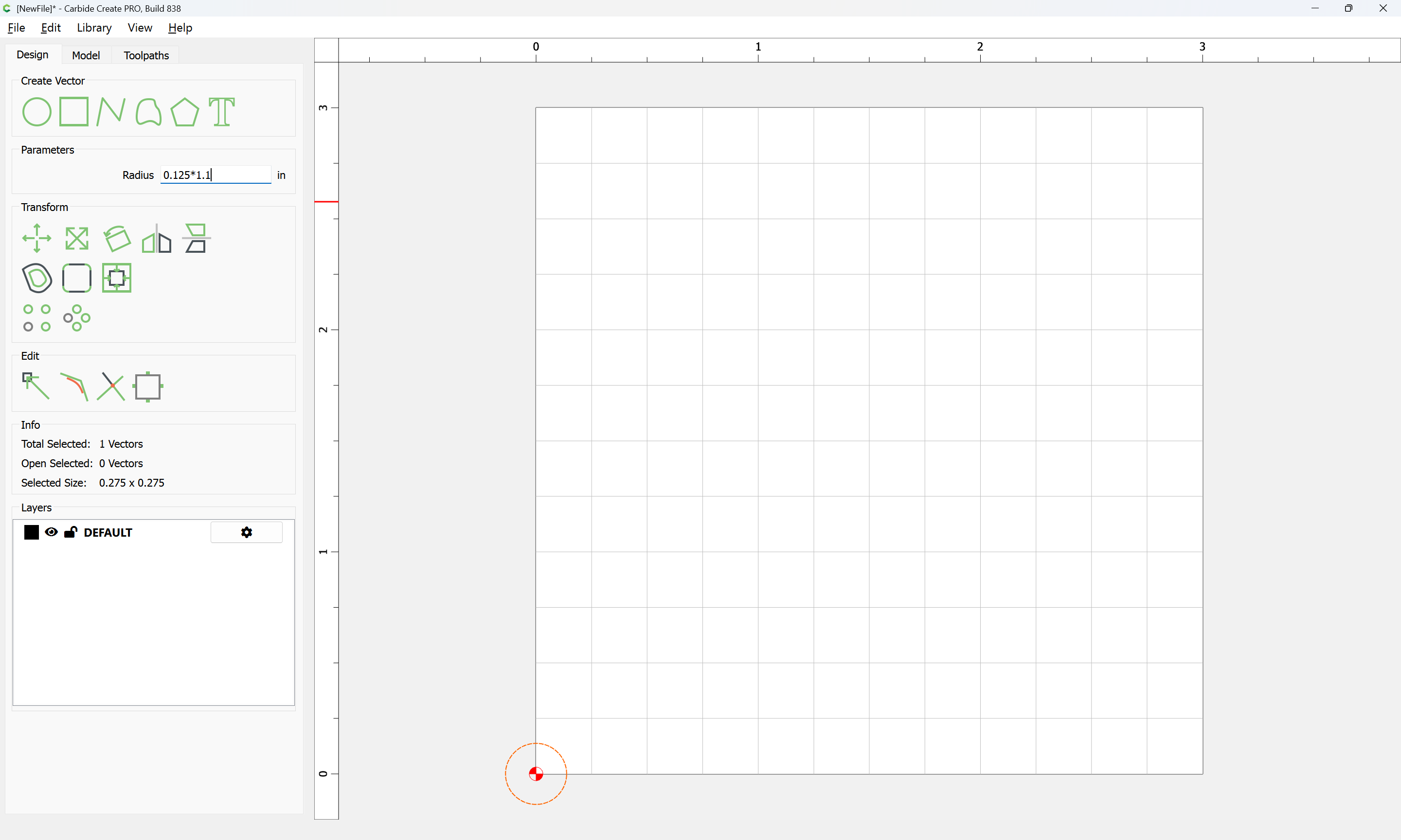
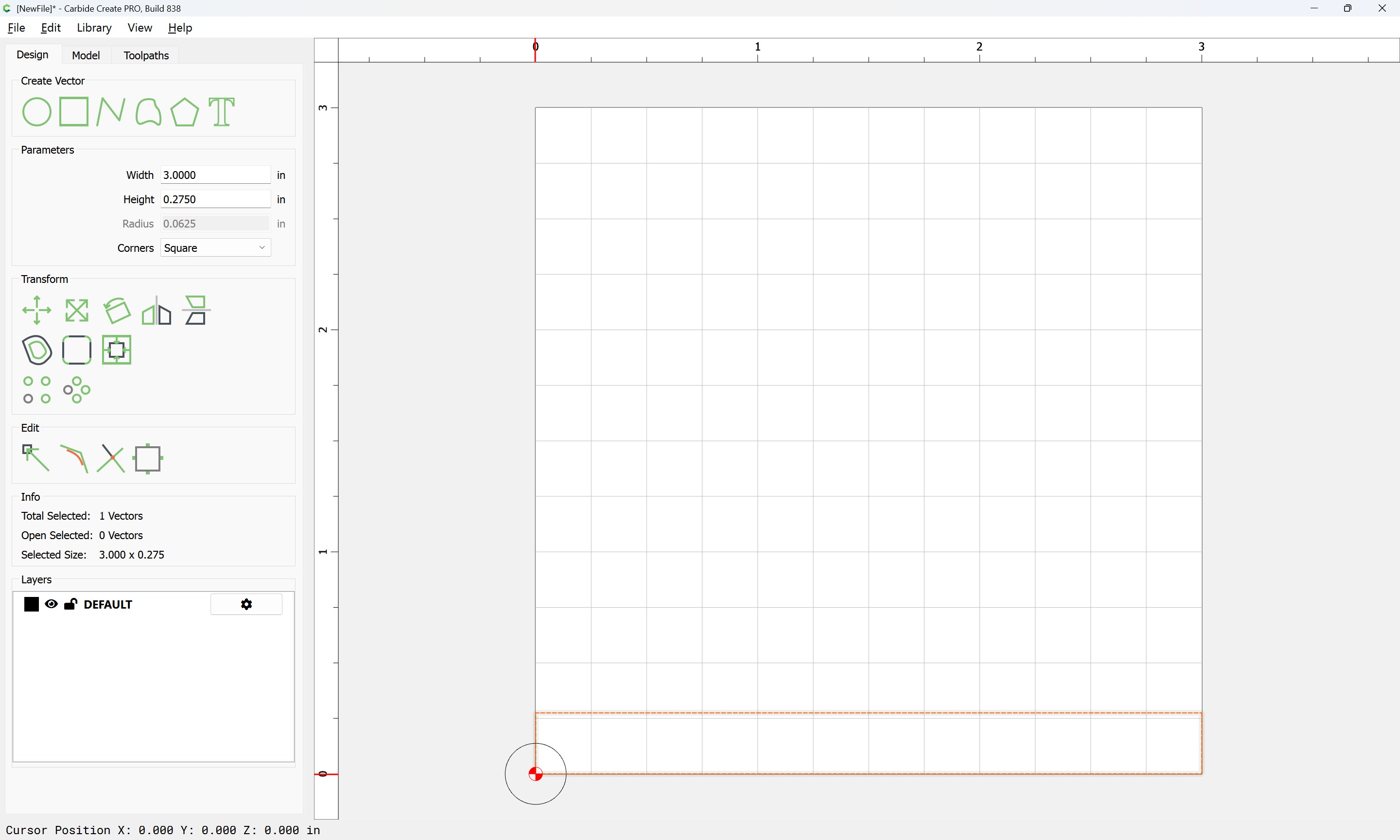
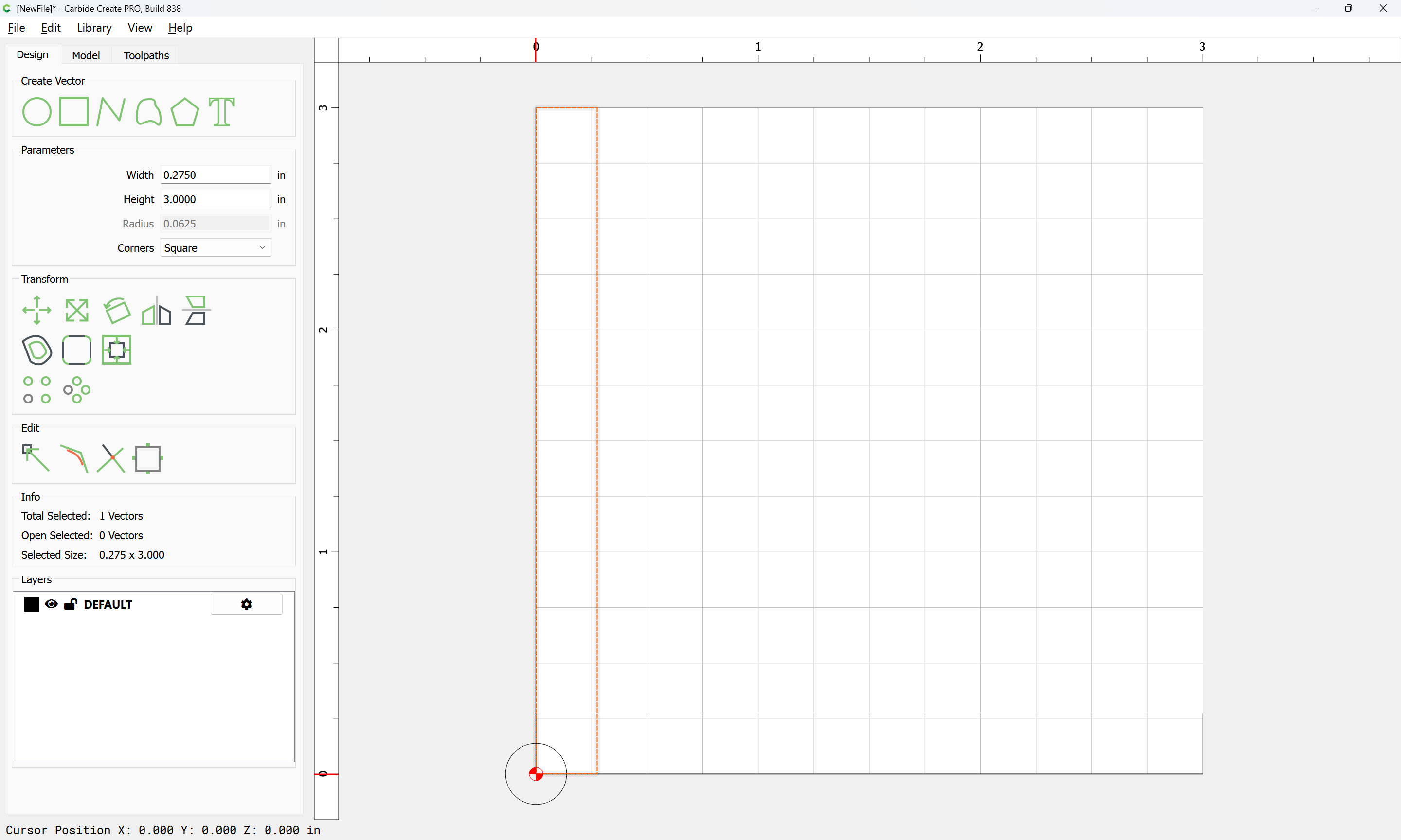
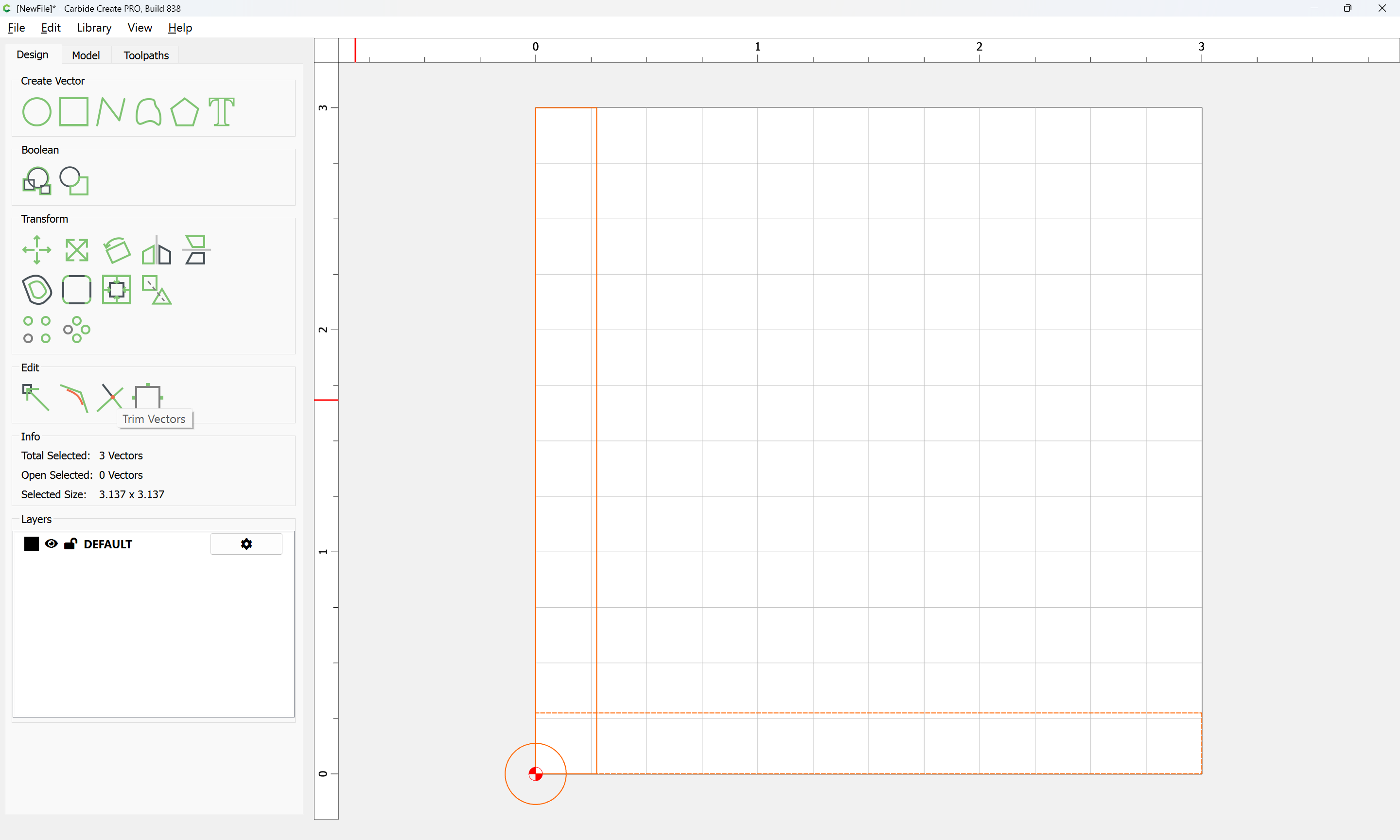
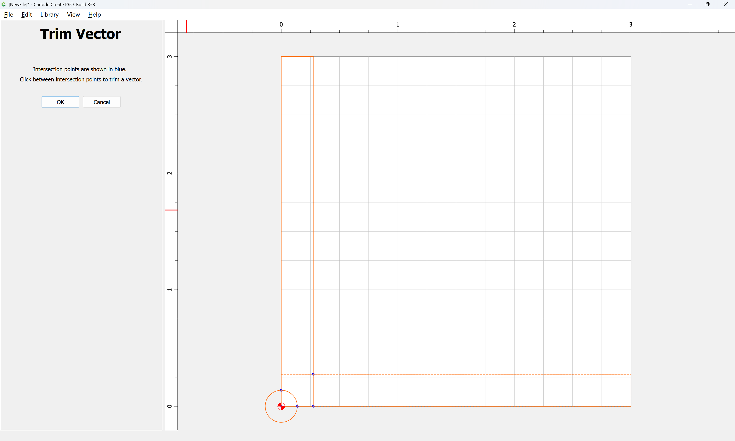
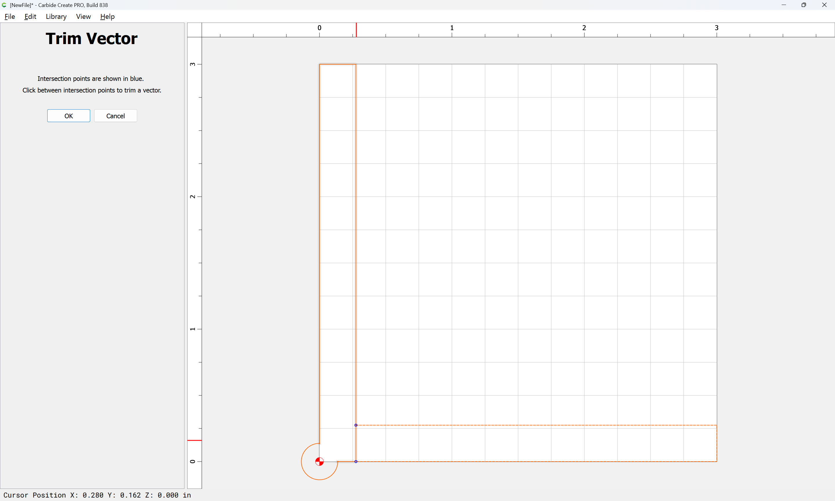
until one arrives at:
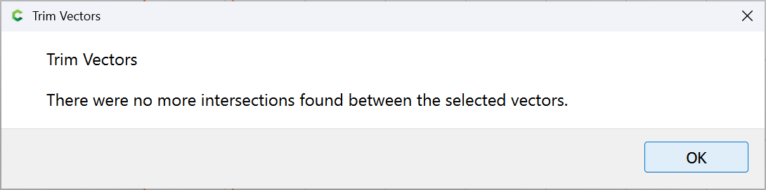
OK
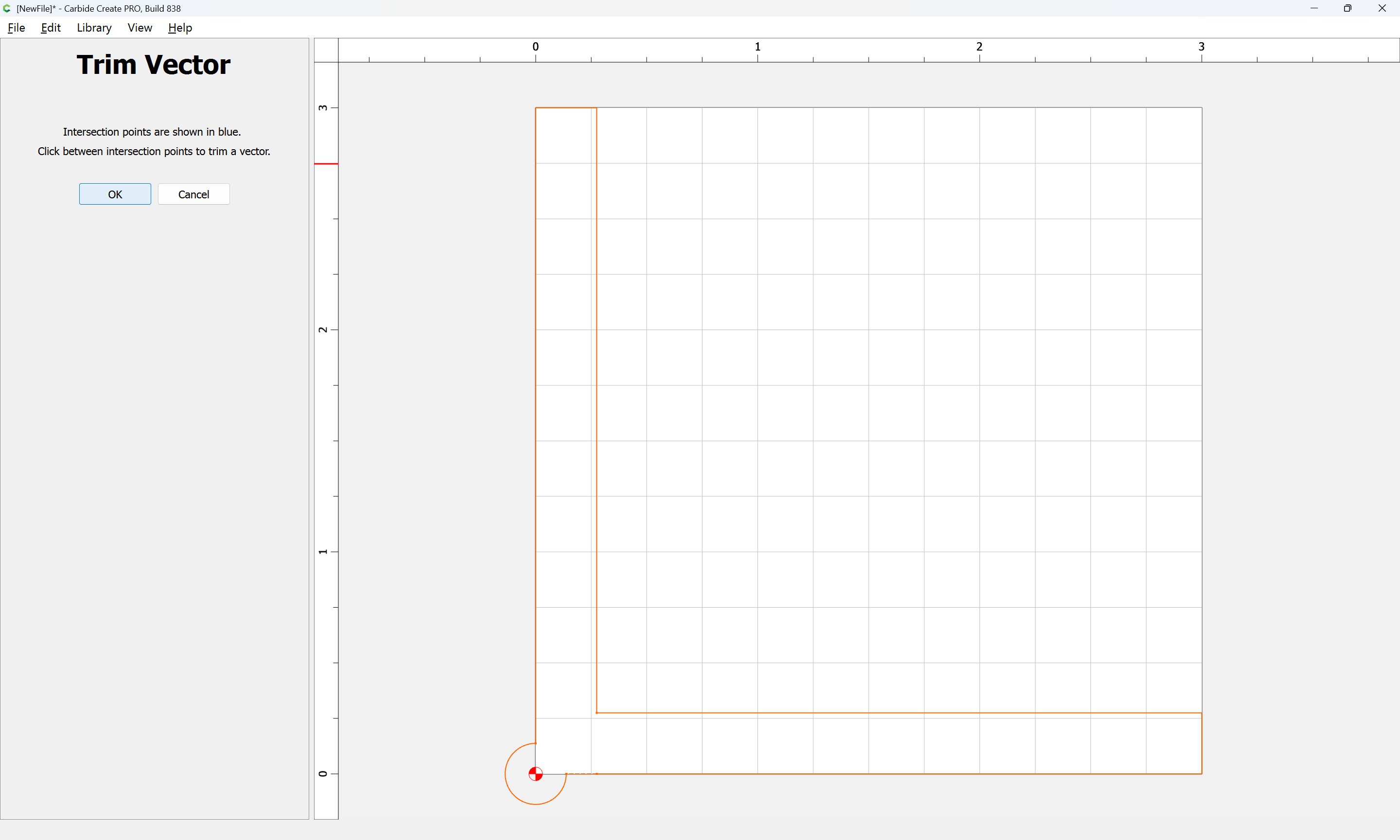
OK
1 Like
It sounds like you’re asking how to make the edge of the fence parallel to the machine’s Y axis.
If programming the toolpath, create a line vector along the Y0 axis, and contour cut it.
On the machine set your zero at the front edge, just a bit inside the edge.

I would just manually machine it. Jog to the back near the fence, turn on the spindle, jog until the tool is just touching the fence, then use -Y jog to machine to the front (climb cutting). Repeat until smooth, jogging a very small amount to the left if necessary to remove more material.|
Once smooth, you can draw a zero mark near the front, and save a quick macro to set that point as your XY zero.
This topic was automatically closed 30 days after the last reply. New replies are no longer allowed.