There are many posts about Emergency Stop solutions. Mine is probably over done for a hobby machine but I thought I would post it for consideration in case someone might find it useful.
After much reading I made this list of considerations for an Emergency Stop on my Shapeoko XL
Separate circuits are used for reducing EMI. One for the router / shop vacuum the other other for the Carbide Motion processor & laptop.
Pressing the Emergency Stop button must cut power to both AC circuits
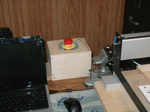
E-Stop switch must be conveniently located - important for this older guy as Father Time marches on and I am moving slower
Use low voltage for the control circuit
Cost - target to be =< than a BitSetter
Design component enclosures for easy access if future troubleshooting is necessary
Document the build if future troubleshooting is necessary with text and photos - in recognition that my memory is not that good 
With the above as a general guide:
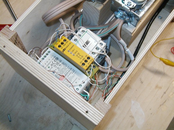
I opted for a 24 volt control circuit which monitors the Emergency Stop switch. When the E-Stop switch changes state a safety relay drops voltage to a contactor controller coil which opens two separate AC circuits.
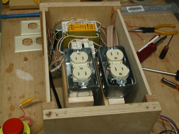
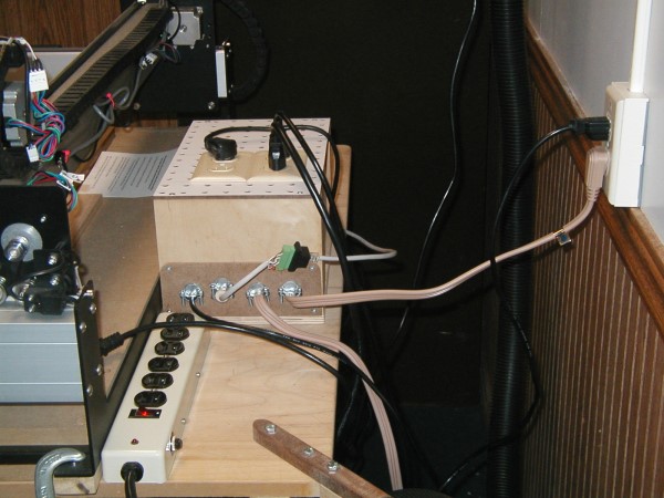
I use one AC circuit to control the router & vacuum while the other powers the Carbide Motion processor. The CM processor has a surge protector on it as well. Separating the processor from the vacuum & router is supposed to help with EMI.
Not the cheapest option but thanks to e-bay & Google I found the major components for an acceptable price.
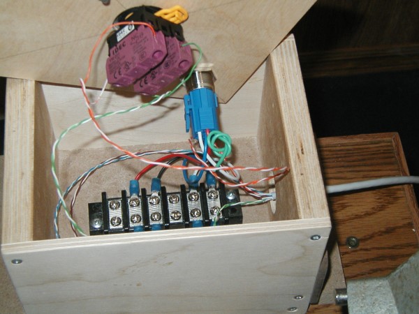
A fair amount of time was spent finding examples of the circuit I could use and then bench testing the design. Wooden enclosures for the control components as well as the E-Stop & reset switch were built. These are larger than necessary for the components but afford easy access if troubleshooting or repair become necessary in the future. By removing a few screws the top and sides of the larger enclosure are removed while the top can be removed from the smaller enclosure.
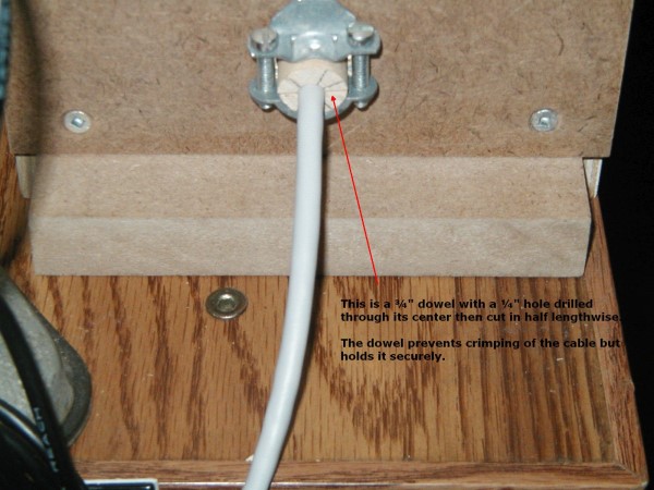
The only issue I ran into was self induced. I used a network cable (it conveniently has four pairs of wires) between the two enclosures with Romex cable clamps where the cable exits the boxes. I managed to crimp one of the wires with the Romex clamp. Using a 3/4" dowel with a 1/4" hole in the center then split lengthwise as a protective sleeve overcame this problem.
A couple photos and a link to the video I used for guidance are below.
I will be updating the network cable connection to a surface mount RJ45 terminal.
Here is a link to the circuit I used for connecting the components.
Emergency Stop Circuit Diagram
Bill