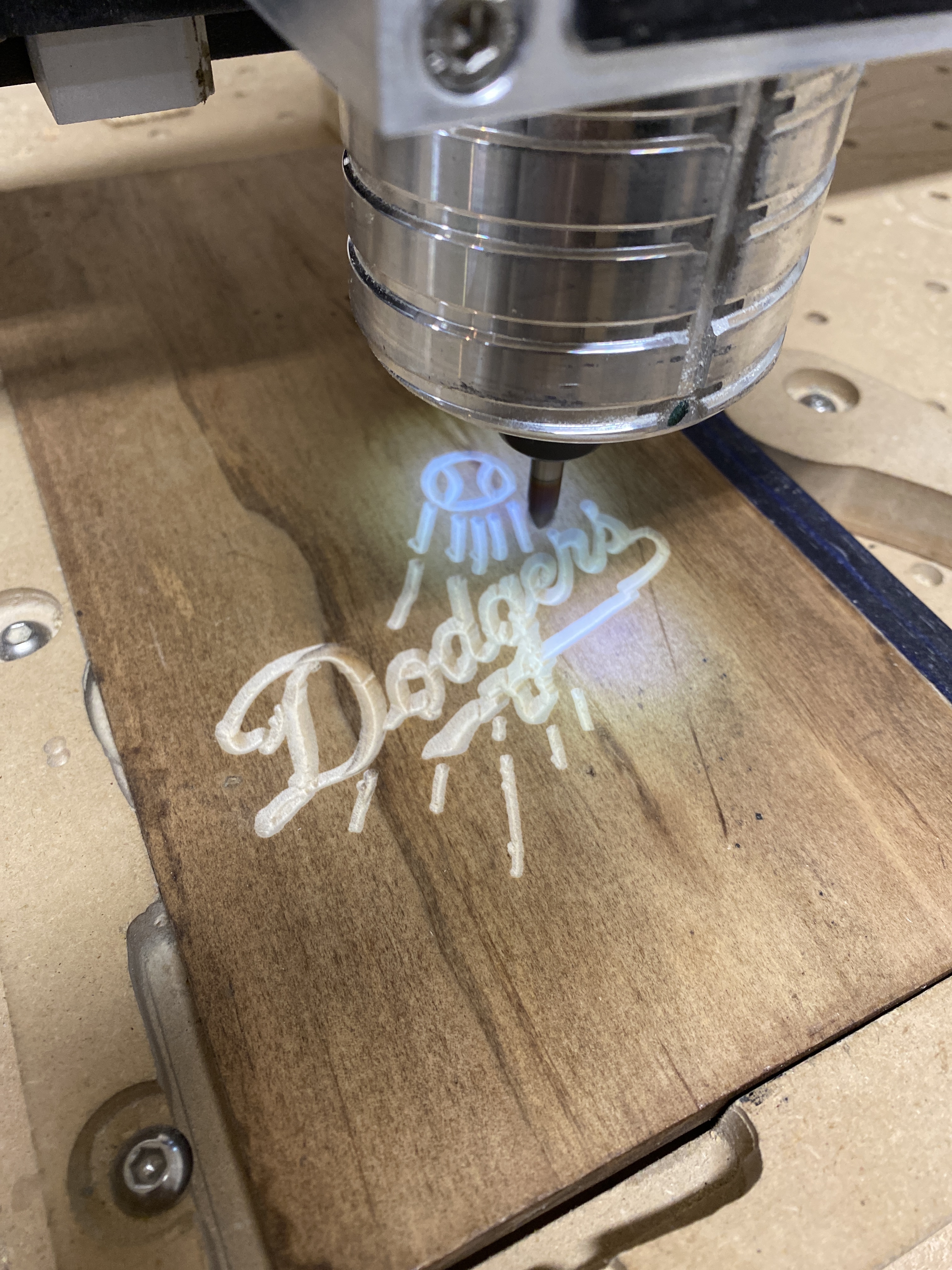
hey guys looking for some help here, I am using carbide create and carbide motion most of my cuts have been coming out clean and no problems but for some reason my cuts recently have not been coming out as clean, when i am preview my cut on carbide motion, the cut looks clean with no extra markings. When it comes to cutting on carbide motion, i am getting extra lines or dots, that never showed up when i previewed the cut on carbide motion. before i cut i make sure everything is zeroed and my shapeoko is properly initialized. I am really stumped on what is causing these extra marks and compromising my work. If this has happened to anyone else or maybe someone knows why this is happening any input would be gladly appreciated, thanks.
sorry for the lack of pics i am working on how to add the images from my iphone since its sayin the images need to be resized
What is your retract height set to?
In carbide create this is in the sprocket menu
Should be at least 0.05 inch or a bit over 1mm
Any smaller and you’ll get marks if the wood is not perfectly flat
1 Like
I double checked my retract height and it is set to 0.05 in height
@mattlo97 in addition to posting pics, can you also post the g-code file you ran please ?
1 Like

24 LAKER BC.nc (29.9 KB)
i dont know if i shared the g code correctly let me know if it worked thaks
Can you upload the c2d file too ?
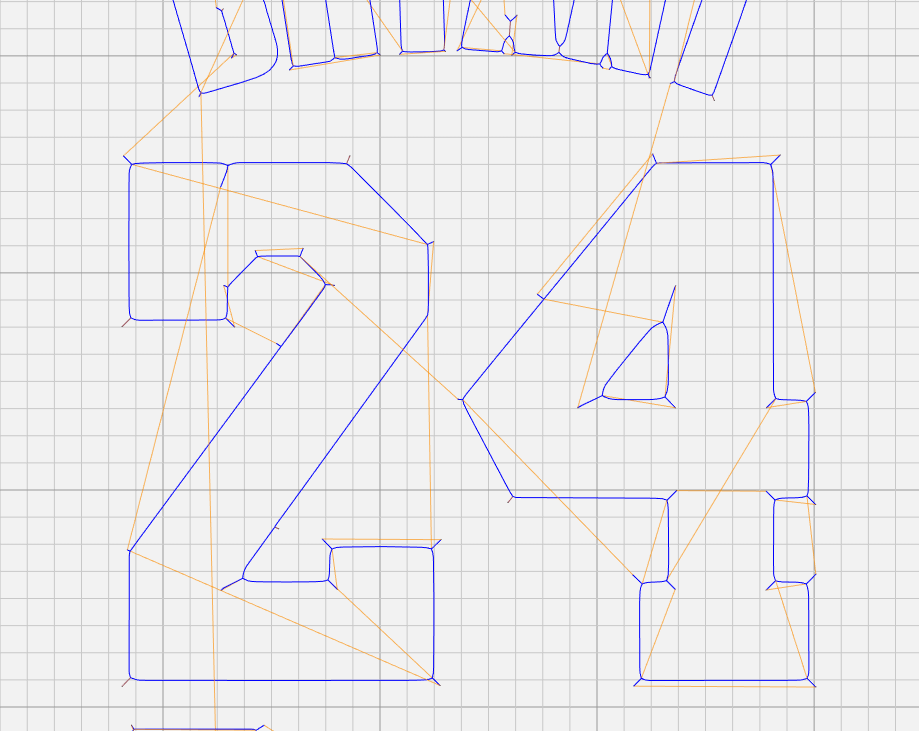
The g-code looks like a v-carving toolpath,
for that cut did you use a v-bit, of the same angle as the one declared in the Carbide Create (where the preview looked ok?)
what is the c2d file? im sorry this is all new to me, i used a 90 v bit but it is not the same 90 v bit that is in the stock carbide create library. that is my other problem is i do not know how to properly add new bits to my library. but i been doing this set up for about a few months and i been getting clean cuts it just started about a week ago to me with most of my cuts
The .c2d file is the projet file itself, the one you open in Carbide Create to edit your design and toolpaths.
For adding tools to the CC library, here’s a handy tutorial from @WillAdams:
Is your Vbit significantly different in diameter than the one you selected in the existing tool library ?
Now, if this used to work and you just recently started to have this problem, it may be something mechanical that went a little loose. Do you have a belt-driven Z axis or Z-plus ? When the machine is turned on and you try to wiggle the router up and down manually, do you feel any play ?
1 Like
KOBE BC.c2d (603.8 KB)
thank you for the add tools forum i will definitely be checking that out. i checked my router and it still feels pretty sturdy and it is belt driven next time it is up and running i will be checking everything to make sure there is no excess play
also when I was trying to cut a simple circle now when I cut the shapoko makes the circle into an egg shape maybe that will help finding out the problem
For distortions while cutting such issues are usually mechanical, possibly exacerbated by toolpath issues.
Check the machine mechanically:
https://wiki.shapeoko.com/index.php/FAQ#Mechanical
calibrate for belt stretch:
https://docs.carbide3d.com/shapeoko-faq/how-to-calibrate-the-machine-for-belt-stretch/
and don’t cut slots only as wide as the endmill which results in the greatest possible tooling engagement — add geometry and cut as a pocket down to at least tab depth:
great feedback I am really starting to think my errors are more mechanical then programing that sounds like a whole new can of worms to me, I bought my machine used so it was already built when I got it, I will be reading up on the links you shared to hopefully fix this problem, thank you so much for the helpful input!
So what have you ticked off the list of mechanical things to check so far ? It seems like there is slop somewhere, have you checked every single V-wheel/eccentric, and Z belt-tension ?
Also, that vbit looks like it is 1/4" wide or so ? Did you succeed in entering that tool in the library with its actual diameter? Just asking because some areas (like the left leg of the D) seem larger than the v-bit, which may lead to unexpected result in a regular v-carving toolpath.
I am more of a visual learner so I found a few videos on YouTube from Chris Powell and Winston Moy regarding tram, and so today i spent most of my day trying to eliminate any unevenness coming from the carriage. I even purchased machinist blocks to determine any unevenness coming from the router carriage. unfortunately I still have the same problem with my cuts coming out as i would describe “crooked”. I checked my belts and they all seem in good working condition I really am at a lost of words and have no idea on how to fix my problem, on top of that its the worst time for a malfunction since the holiday’s are around the corner saldy.
1 Like
Hi Matt,
Don’t worry we got you.
Tramming is not your problem. Tramming problems should show up as vertical or horizontal ridges in flat surfaces.
Squaring is probably not your problem either, it would show up as distorting features evenly across the cut (e.g. a square would look like a lozange, a circle like an angled oval)
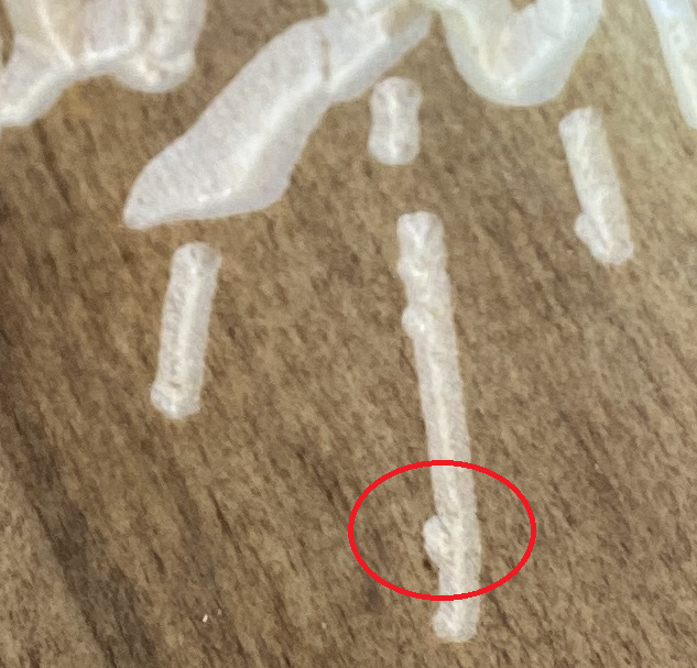
In your cuts we can see lateral shifts during what should be straight/smooth moves :
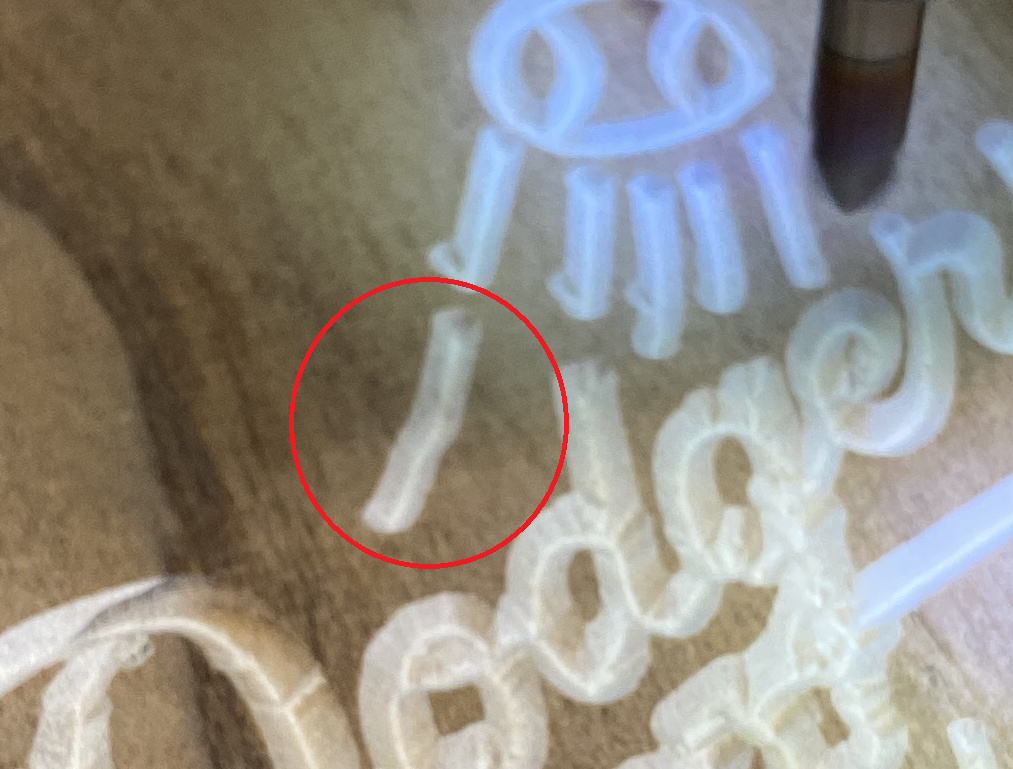
This is usually due to mechanical slop somewhere. Really, start be inspecting EACH v-wheel (the four ones on the X/Z carriage, the four ones on the Z axis if you have a belt driven Z, the four ones on the left Y axis, and the four ones on the right Y axis), and make sure none of them can spin freely.
The belts may be in good working condition, but how tight are they ? especially you Z axis belt. If you pluck it, does it make a nice “twang” sound?
Once you have done those checks, do the following test: power on the machine, jog it to the center, leave the router turned off (better yet: unplugged), grab the tip of the endmill and try to wiggle it left/right/front/back/up/down, and check if you can feel any slop.
Also, how do you set Z zero, and can you confirm your entered the correct vbit angle in the custom tool you created ? The picture below tells me that either the Z zero is set a bit too low, or the vbit is wider than what is declared in the tool library?
1 Like