Hi, we recently purchased the Z+ kit, which came with some new proximity switches.
After putting the whole machine back together, homing it hasn’t been working.
It does the Z-axis fine, and starts moving along the y-axis, but it never starts moving in the x-axis. As soon as it senses the y-axis limit, it throws a “Limit Switch Error ( X )” then a “Homing Cycle Failed” and finally “GRBL Error: Homing failed, pull off didn’t clear”
The limit switches themselves appear to function correctly. If I put a metal ruler in front of the sensor, the light turns on.
From what I understand the “pull off” is the backing away of the machine from the edges to depress the sensors. I used the MDI to try to change the setting ($27 according to https://github.com/gnea/grbl/wiki/Grbl-v1.1-Configuration) from 3 mm to 2 or 4, but it doesn’t make a difference.
The weirdest part is that the issue briefly went away for a while, without me doing anything that I can remember. But now it’s not working again.
One other thing that might be related is that when I go into settings, under GRBL Active Input Pins, X is listed. I don’t remember if anything was listed there before.
Have any of you guys encountered anything similar? Any advice?
I recently installed teh refit on my machine, and one thing I learned was to manually move to the near-homing place (and then turn the machine on) to make sure they all light up (and adjust until they do)
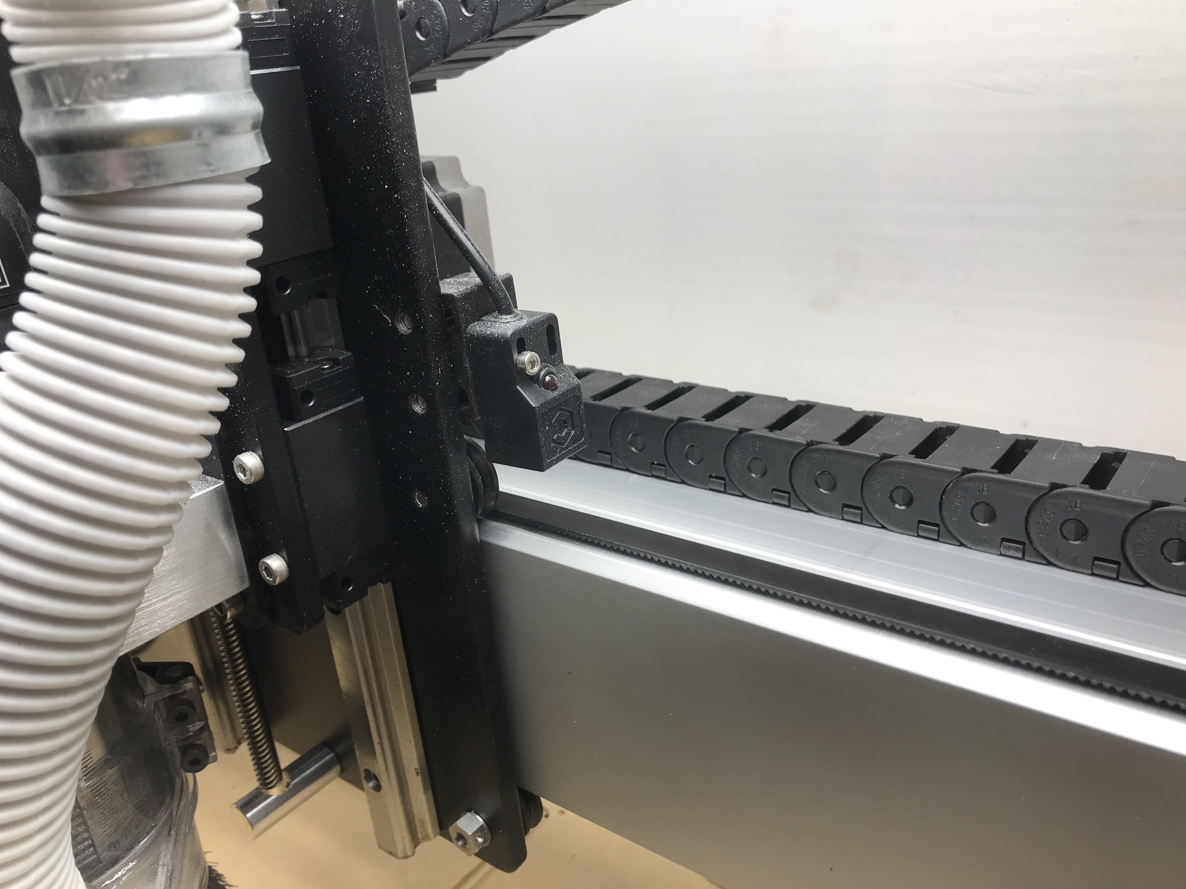
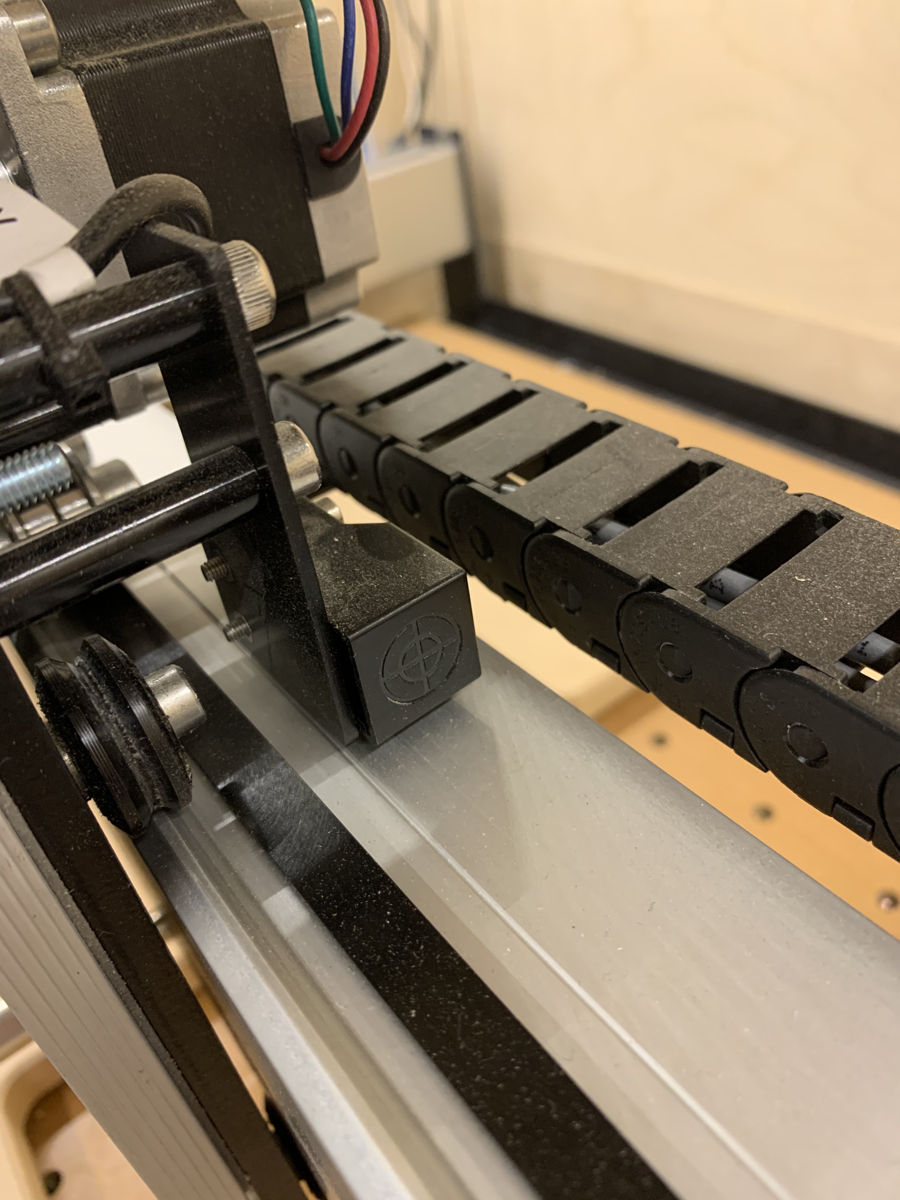
seems the inverse is also needed, to make sure they do NOT turn on when not at the end. Can you take a picture of the X sensor (e.g. how it’s mounted)… it’ll be on the Z+ carriage
Guess I can’t undelete a post, so I’ll reply again. That seems like an odd approach, no? To trip sensor as it is passing over the plate, instead of driving up to the wall?
Anyways, I guess if it’s working on yours then I stand corrected!
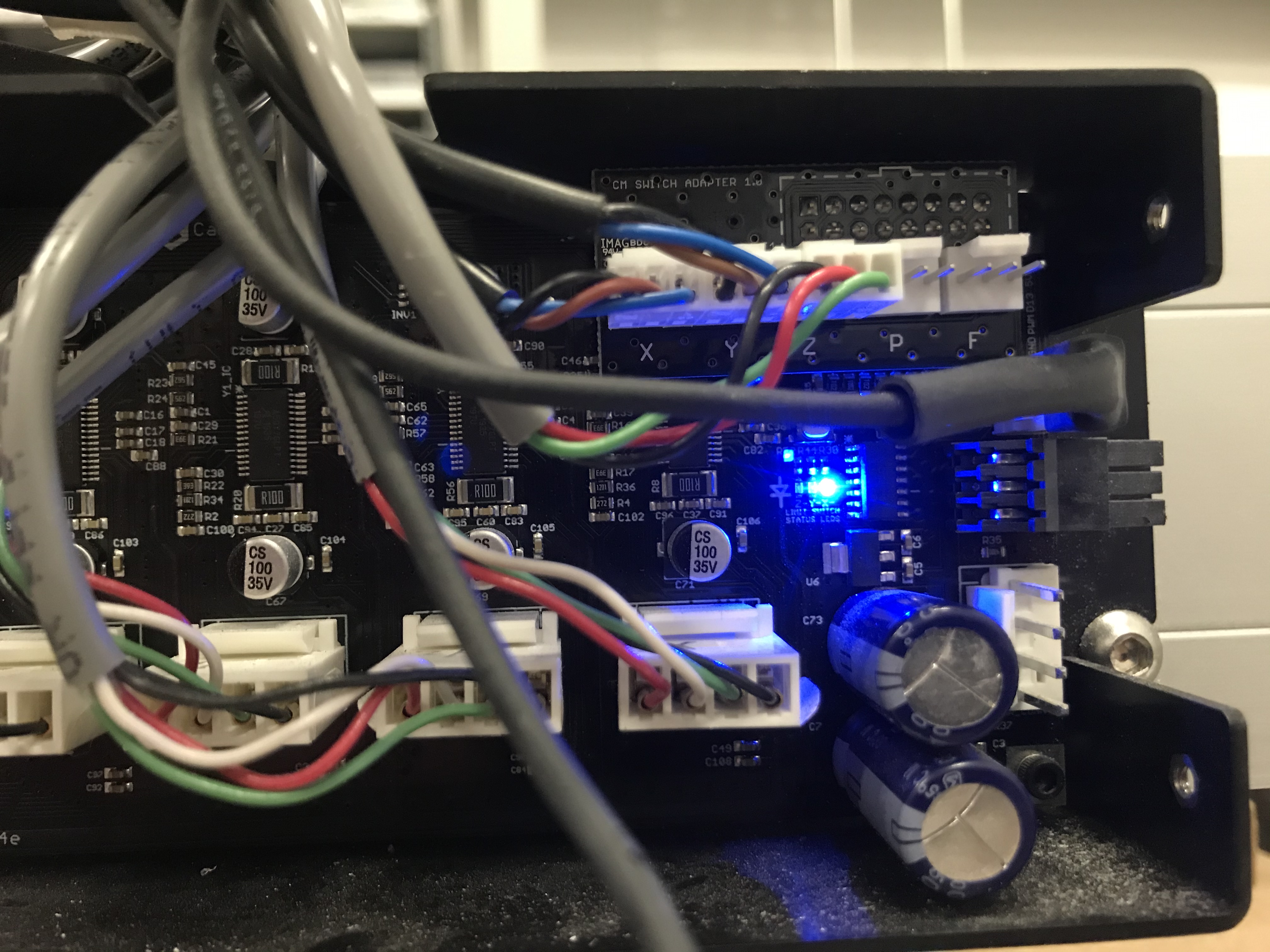
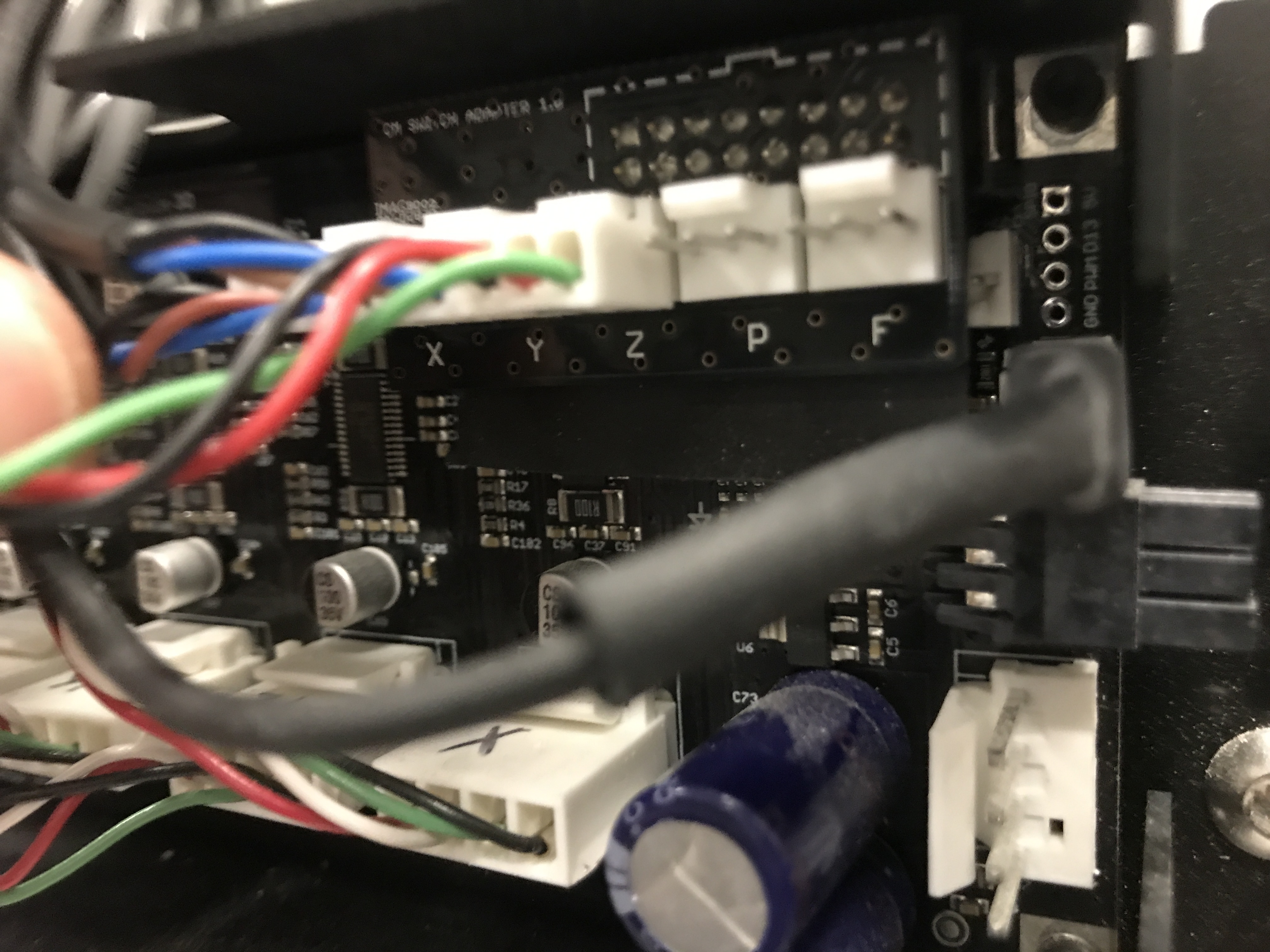
If the little circuit board with the limit switch wires attached is bumped or pushed or tilted a little bit, the x light in the circuit board turns on:
The wires being upside down was a good guess, but the thing is I got it working once.
This explains why I suppose. I must’ve pulled on the wires a bit once so that the x light turned off.
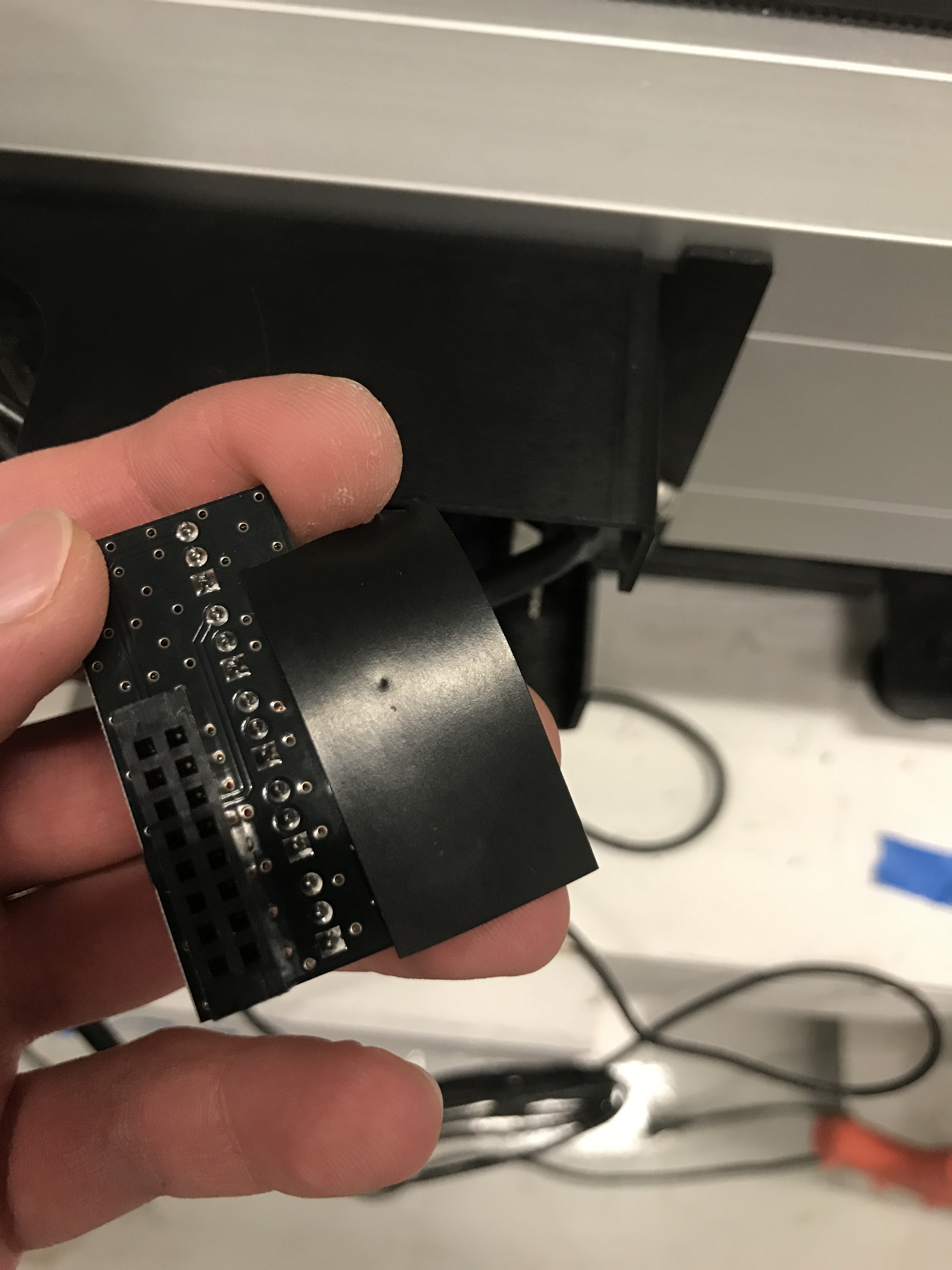
I’m not sure it’s a bad solder. I think the PCB riser board is touching the old limit switch leads on the main PCB board.
I put a piece of tape on the pins and put the riser board back on, and that’s helping.