Ahh, right, sorry, I was referring to the regular shapeoko board (v2.4e) with the riser necessary for the z-plus, I have no experience with the Pro version board. Either way it is good to know there is a difference, thank you for the info!
2 Likes
Most 12V LEDs will not light with only 5V.
Look at it this way… An LED needs x volts to light. It is wired in series with a resistor to lower the current going to the LED. That resistor also lowers the voltage getting to the LED. If the supply voltage is not enough after the series resistor uses some of it, the LED may not reach it’s threshold for illuminating. Ohms Law rules, but the current limiting resistor and its impact on voltage to the LED must be considered.
I used the PWM as an example of how LEDs are conventionally dimmed. It’s not as simple as lowering the voltage. In dimming applications, PWM is used… not to pulse the light, but to chop up the amount of energy getting to the LED. Narrower pulses = dimmer LED.
The PB surely has a limiting resistor in series with the LED. If you could change that, you might be able to use it on 5V, but most of the time 5V will not be enough to illuminate a 12V LED, or will do so poorly - not much help in a situation where the whole idea of the light is to get you to the button in a panic situation!
I don’t want to derail this thread, but that’s not really how it works. The LED had a forward voltage which is not known without a data sheet and it’ll use what it needs, to a point. The resistor will use what’s left and slow the current for the circuit, dimming the LED.
Try it. I might be wrong, but I doubt they’re using high powered LEDs in those cheap buttons.
I grabbed some basic blue 12V utility LEDs with built in resistors. Connected them to 5VDC
Some lit, some didn’t, some were noticeably dimmer. Red LEDs were more forgiving of the reduced voltage. (red LEDs have a lower forward voltage than blue)
In any case, I would think our friends at C3D would prefer that instead of hanging another item onto their controller board, a simple 12V wall wart (<$5) would be the best solution to power (at full brightness) the LED PB!
… and now back to the topic. Hope the slight sidetracking is OK…
I have a bunch of 12v switches, they light up fine at 5v. So id try it @5v first before overcomplicating things.
Mine get marginally brighter up to 12V but mostly the current draw doubles (my cheap power supply says 4ma at 12V)
1 Like
@Intohouse, Sorry for the delay. I’ve been offline due to Perservence landing. We did the chip in RIMFAX…
The comments below are correct and as far I can see, there are no LED control for FEED_HOLD output from Pro controller board. The future setup for feed-hold as a product should be something similar to the BitZero with protection circuitry and a board with Schmitt trigger to reduce contact noise (which can and probably already is implemented in the sensor interface software on the AVR), and to prevent over voltage etc… LED control on the BitZero is handled one that device itself with a small circuit board inside. LED power by 5V. The wiring to the BitZero is therefore 5V, GND, and the Probe signal.
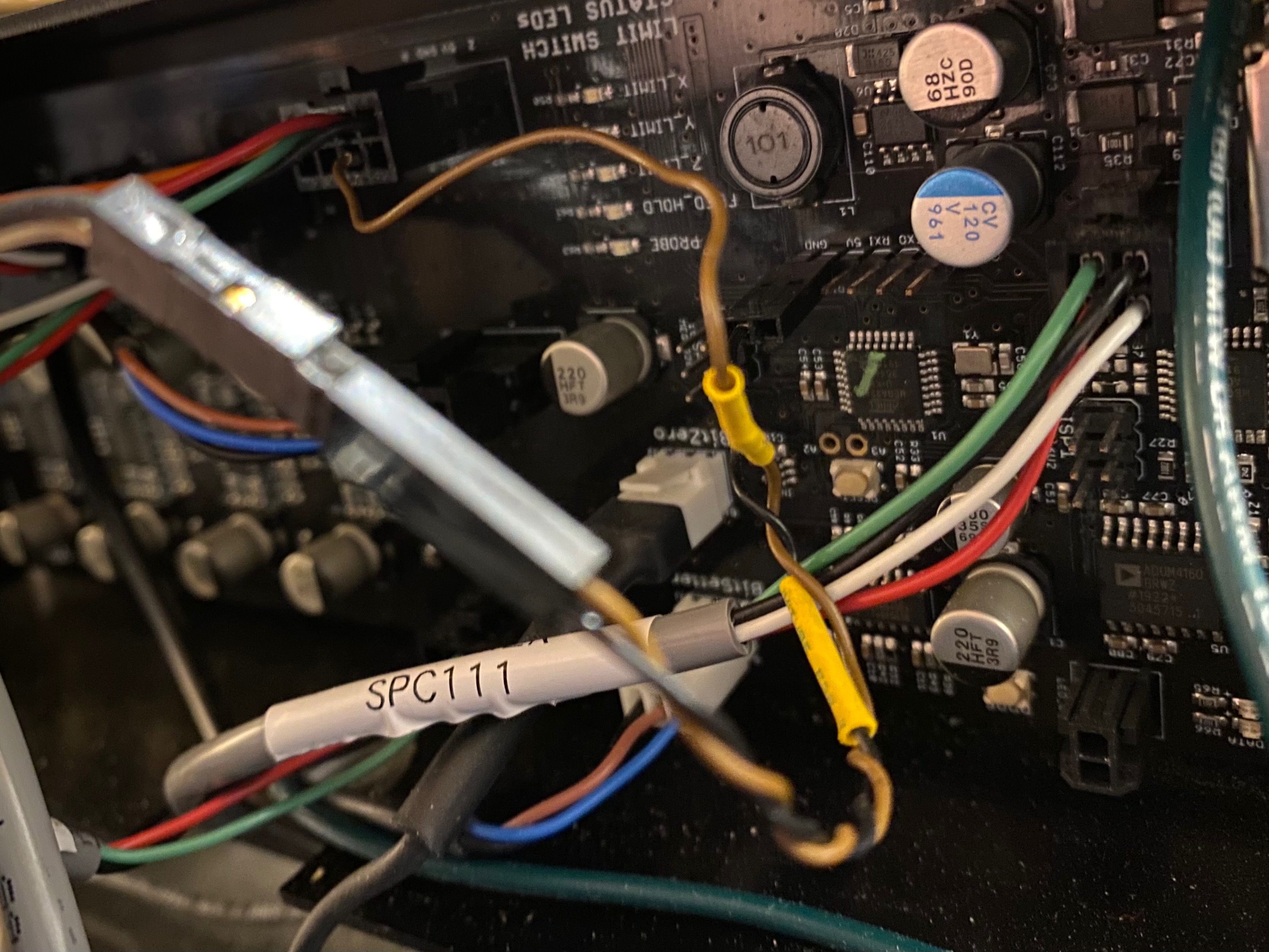
As @ChrisXL says, getting the new wire inserted and locked into the connector is a mess, and the size of the female pin header is somewhat smaller than “standard” pin header. I hope C3D will make T-shaped breakout in the future. I am actually a bit surprised that this signal isn’t available on a separate connector like the BitSetter and BitZero. That said. Straight wiring works. You can even use the Bitzero Grounding strip as GND (from my side not recommended though). In picture FEED_HOLD signal (brown), GND (black) and some yellow crimp as I needed to extend the wires a little bit.
2 Likes
Be very careful with current draw on the 5v line, the controller board really only creates enough 5v power to run itself and a few ‘logic like’ interfaces, such as the end-stop sensors. LEDs take 20-50mA of current, depending on which type and how bright, and I reckon there is only about 50-80mA ‘surplus’ from the 5v regulator circuit. Pushing this too far might result in the controller board shutting down randomly, once the regulator has reached its maximum temperature…
The regulator is coping with a power dissipation of (24v-5v) x current A, and the designer must have assumed that nothing else would pull 5v power and thus opted for a simple, linear regulator down from 24v - the power dissipation just fits within the thermal limits of the 7805 regulator…
3 Likes
To be clear, the LED in this application is not used as an indicator light. It’s just there to light the button so it’s “easier to find” in a panic pause situation.
There’s no logical (excuse the pun) reason for it to be powered from the controller board. A cheap wall wart (5V or 12V as you prefer) gets the job done with complete isolation! If the wall wart is plugged into a power cord after the main power (emergency off) switch which most of us have, it will light the LED when the Pro is powered on.
Easy peasy.
Yepp @theworkshope, I did the reverse engineering of the Pro v3.0b after all. More or less the entire board, but some pieces are still missing, and findings needs to be tested first, so I make it in text rather than in schematics for now. Inputs are highly appreciated…
Usedful link for pinout: https://shapeokoenthusiasts.gitbook.io/shapeoko-cnc-a-to-z/anatomy-of-a-shapeoko#controller-board
V3.0b is in my opinion generally a very good design, but I wouldn’t be surprised to see a revision C with some minor adjustments.
All input signal like limit switches, FEED_HOLD and PROBE signal has got an input noise suppression filter that will also work as protection circuitry for the Atmega328 (motion controller). That´s great!
The 6 pin BitRunner connector seems to have 24V, GND and PWM used for controlling the router in ON=5V / OFF = 0V, as default or PWN (see the above link). The “PWM” signal is connected directly to 328 uP pin 15 - PB3 which is a multipurpose config options: PCINT3/OC2A/MOSI. This signal is also available on one of the ISCP connector pins (used for firmware loading).
For the remaining three signals, one seems to be unconnected, two reserved signals are connected directly from pin 22 (PC7 (INT4/ICP1/CLK0) and pin 23 (PC6 (OC.1A/PCINT8) on the ATmega16U2 (USB interface controller). For what I would guess, this is how it should be if future or now (don’t know) could be implemented as a fail safe mechanism to kill router if the motion controller gets stuck. The motion controller should only adjust router speed (as from what I’ve read is what the PWM is intended to do). The PWM frequency seems to fixed.
The reason for a possible revision C is that all three signals seems to be missing som boosters and/or protection circuitry in between the connector and the uP. I guess they are all intended to be outputs. In short: BE VERY CAREFUL NOT TO SHORTCIRCUIT ANY OF THESE WITH THE 24V! THE BUILT IN ESD PROTECTION CIRCUITRY IN THE ATMEGA328 WILL FEED THE HIGH VOLTAGE DIRECTLY TO THE 5V POWER RAIL AND POTENTIALLY KILL BOTH CONTROLLERS AND MORE.
What needs to be tested is if there is also some kind of a watchdog included like as if the signals are somehow altering during run to indicate that the USB controller and PC interface is alive and kicking.
EDIT AFTER TEST: Didn’t find any such.
X12 connector have the same signals, but with a slightly different pinout for NC, pin 22 and pin 23. The 24V, GND and PWM is mirrored from BitRunner.
The SPIO soldering pads includes PWM and the D13 is also found on the ICSP.
3 Likes
Convenience.
@npross Measured only 4mA draw on a 12V source. I measured less than 2mA on a 19mm button connected to an Arduino’s 5V.
I think you’ll be alright using the 5V from the board.
Thanks for the follow-up @Norway! Great level of detail, I definitely would not have dug this deep myself.
1 Like
@mingle, the Y2 signal seems to go nowhere else than in between the X, Y and Z limit connectors. A bug in the circuit board perhaps?
I’d be surprised if that was the case. Any chance it’s connected to the Z switch input?
I purchased some mini-fit jr connectors off of Amazon just to nab a crimp skt for getting access to the F pin. Unfortunately, the mini-fit jr are larger than the connectors on the board, and the socket does not fit. Can someone confirm what type of connectors are on the board, or a compatible part number for a crimp socket? Thanks!
There’s a comprehensive post EDIT for the SO3 (not the Pro) at:
and the wiki in question is at:
https://wiki.shapeoko.com/index.php/Shapeoko_3#Connectors
(but doesn’t cover the Pro)
Thanks Will, but that post is for the SO3, not the Pro.
With the aid of a flashlight, I found a faint marking. Turns out they are micro-fit 3.0 connectors.
1 Like
Just stumbled on this post, very cool! I am indeed wishing for a feed hold button. The touch screen, trying to hit that tiny pause button is a bit nerve racking, but reaching for the e-stop is overkill. (The time between fumbling for pause might mean the difference between a simple resume versus e-stop  )
)
That’s correct. I accidentally identified them as mini-fit. They appear the same when you ignore the scale. Where are you located? I can send you a pin or two.
2 Likes
Greg,
your observations are correct! A quick pause is much more recoverable than a e-Stop.
I have made many plug-in pause buttons for SO3 friends on the Shapeoko FB page.
A while back I completed the design of a PRO Plug and Play version. Intohouse (Brandon) and I have had a number of discussions, and he was the first to get a Pro Pause that I designed. We tested it together via Zoom, and it has worked well!
Since then, I have made some for others on the FB group. There are currently a number of PRO and Regular Pause buttons that I have made…
It’s not brain surgery, but by designing it so that it is plugged between existing cables, there’s no pin making or soldering required by you! Because they are a PITA to build the mini connectors, I sell them for $59. I’m a former electricity shop teacher and ham radio guy, so I can build them, but it does take time.
I offer them to others as a fellow CNC’er, not as a business. I’m sure that at some point, someone in a related business will grab the design and replicate it for the masses… 'til then I continue to make them for fellow CNC’ers!
(saving up for a PRO little by little!)
More info: message me!
4 Likes
Thanks for the offer but I am well equipped to make one. Hardest part will be matching the SO Pro’s button, but that’s just cosmetic in the end
1 Like