the VCarve method described uses the fixed angle of the Vbit.
That’s not the angle to which I’m referring. It’s the angle at which the base needs to held to have both sides of the inlay opening parallel to the CNC bed. Each side runs along a different bevel cut into the top of the hexagonal base.
OK, I’m still working with Carbide3D support on getting my new Shapeoko Pro Std up and running (they’ve been great, but it’s kind of drag having multiple issues), and in the meantime I’m modeling in Fusion360.
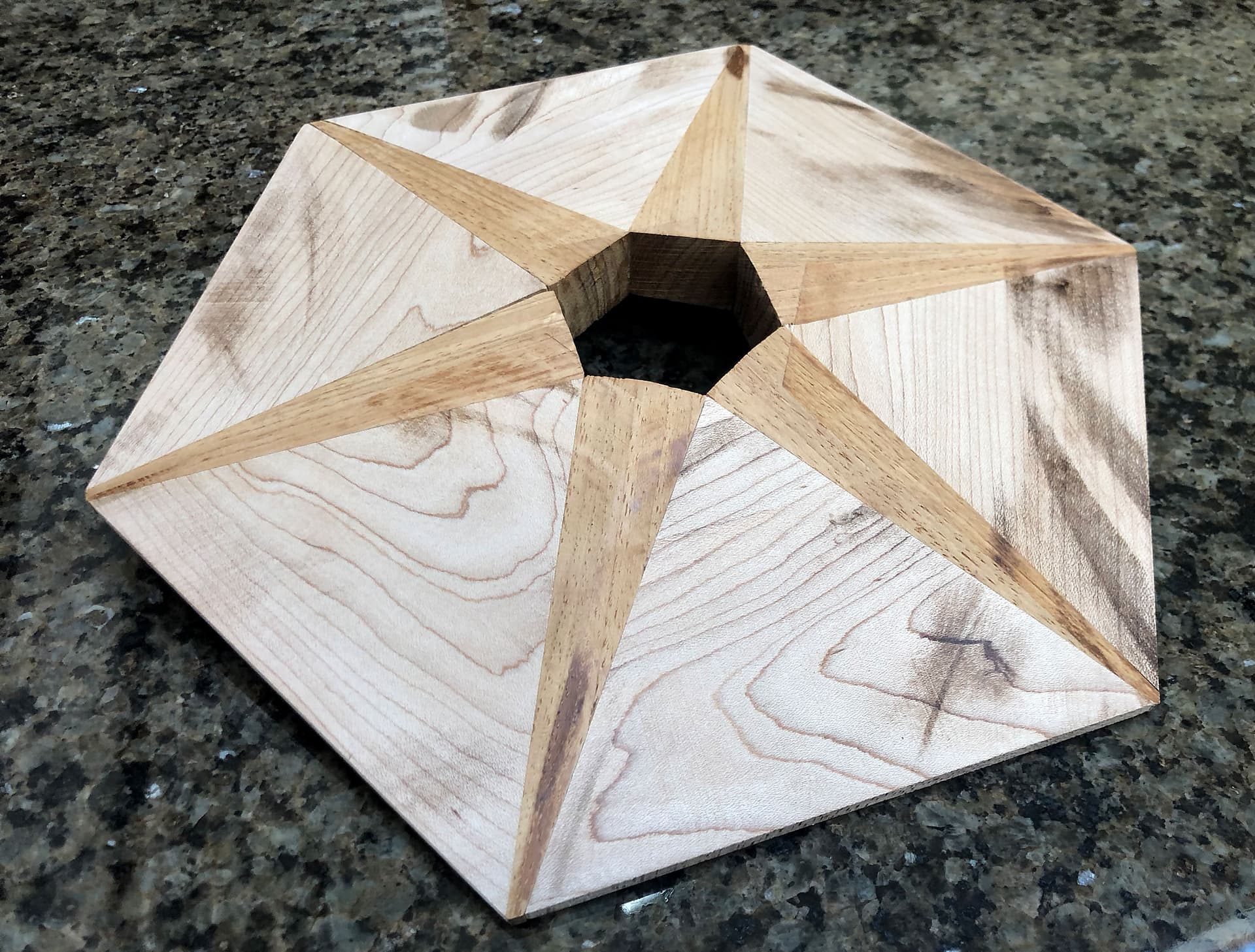
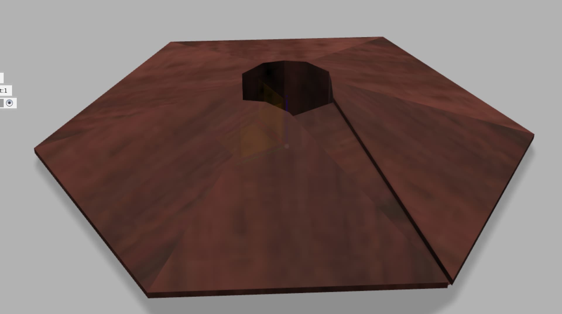
I decided that since my staircase posts aren’t perfect hexagons, that I was first going to mill the thing traditionally in the lighter wood and then use the Shapeoko to both make the darker wedges as inlays and to cut out the inlay recesses. This way any gaps in the traditionally made base will be completely covered by the CNC made inlays.
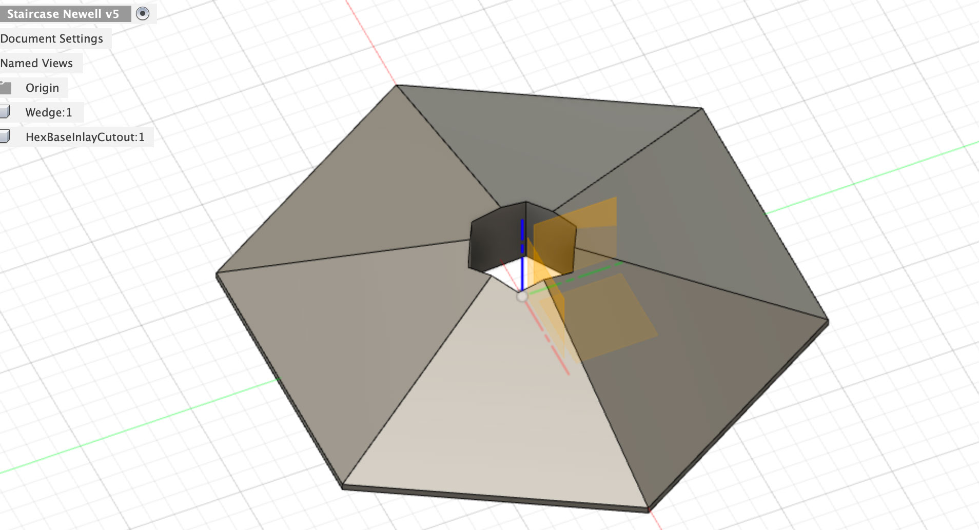
What’s the best way to about this? I can probably make another component or body (not sure of my Fusion360 terminology) that represents the wedge, but then how to I design the cut-out inlay? And I don’t want to cut all 6 recesses at once, my plan is to rotate the “base” for each recess cut since the sides won’t be identical. I’ll reference off the point of the base, which is also the point of the wedge inlay. I just need to design for one inlay recess, since I’ll run that job over and over for each of the 6 inlays.
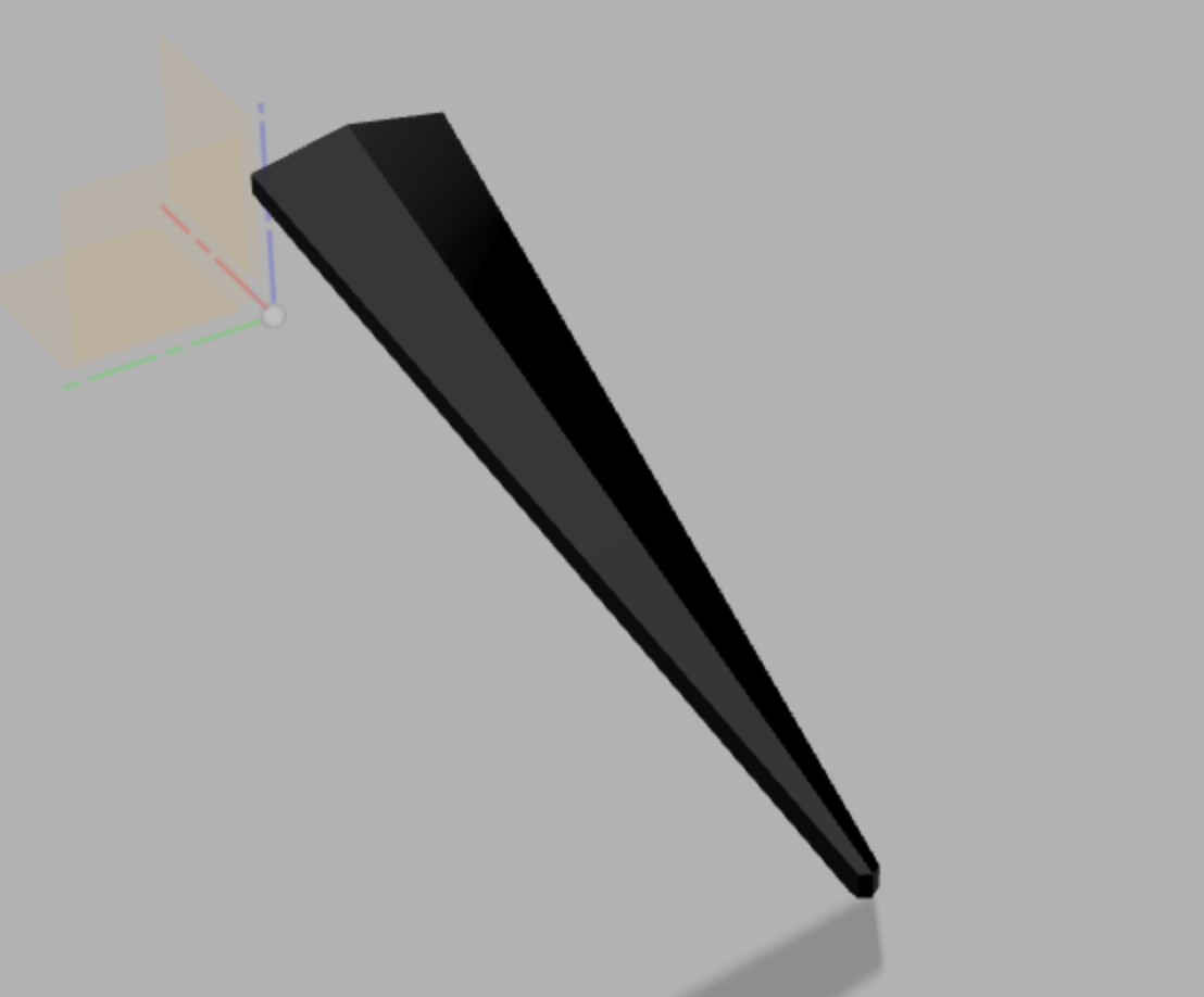
The dark wedges aren’t just flat veneer inlays. If you look closely at the photo and the Fusion360 model, there’s a peak running down the middle of the wedge. My plan here is to cut the wedges thicker than I need and then sand them down using a disc sander. I’d love to cut the whole shape using the Shapeoko, but given the non-regular hexagonal base that doesn’t seem practical.
To summarize my questions:
How do I model/design the recess (after I construct the wedge body)?
How do I use Fusion360 (or Carbide Create) to construct the tool paths to only cut the inlay, since the base will already be cut?
Is there anything special I need to do when modeling the recess given that the wedge will be designed to stand proud? I’m assuming not since the recess will have flat bottom as will the wedge.
You don’t necessarily need to. Once you model the wedge, you could use the outside contour of that wedge as (one side of) a selection for a toolpath milling the recess.
If you do want to model the recess, you could use the Combine function to do boolean subtraction, using the modeled wedge as the part to be subtracted from the base
It’s all a matter of selecting the appropriate contours in the toolpaths. If manual selection is too tricky, a good way is to use projection onto a sketch of the contours you want to use for the toolpath, and then use that projection as the selection in the toolpath
Potentially, a little tolerancing/margin between the recess and wedge? but given the wedge shape, it’s probably not necessary anyway.
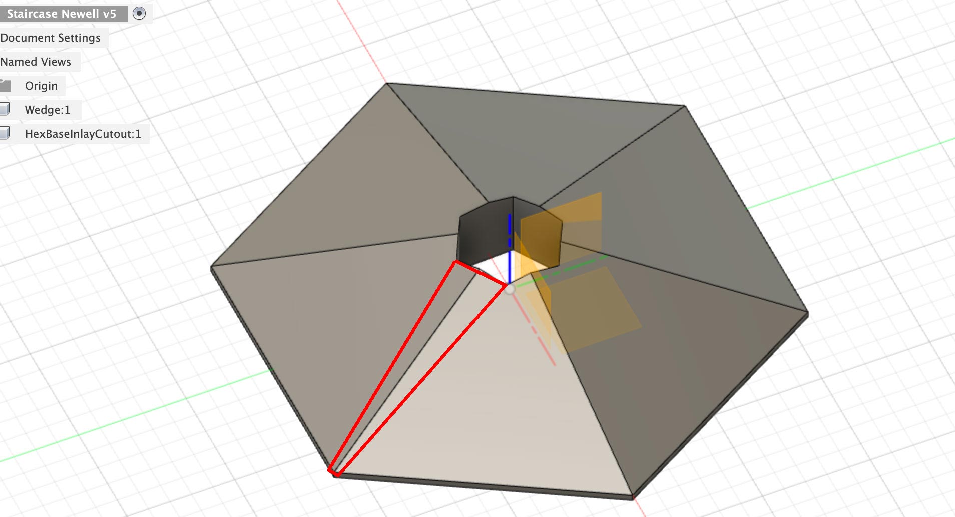
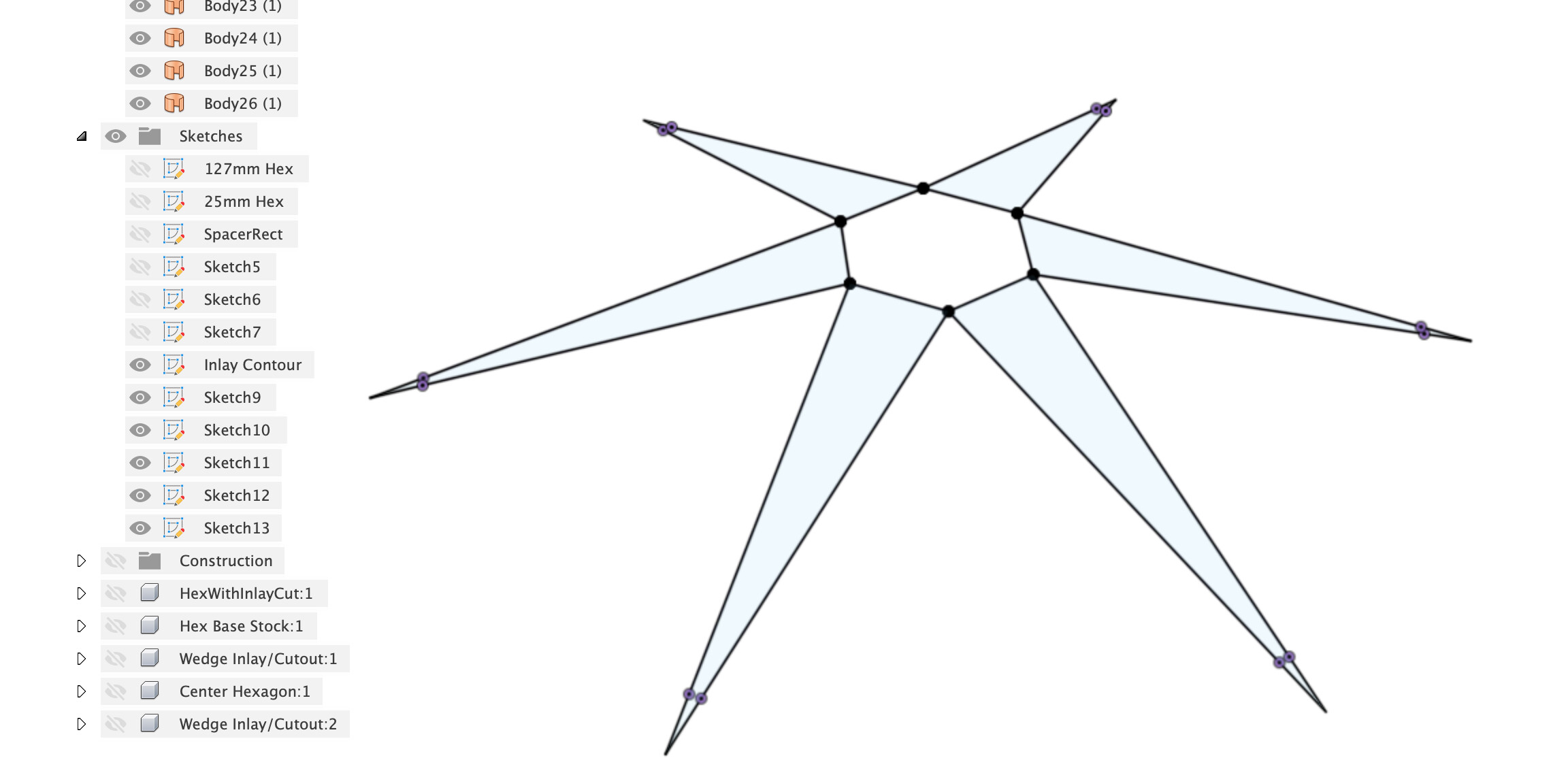
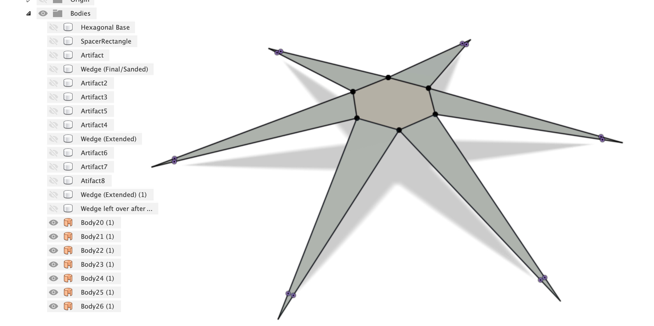
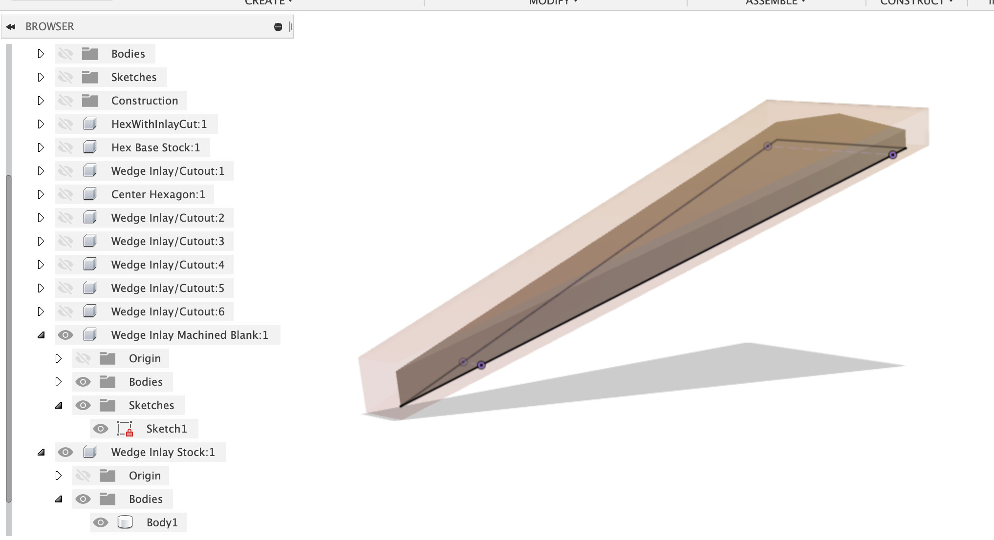
Thanks. On modeling the wedge, I need to somehow build that off of the hex base body I’ve just made. The wedge is really a trapazoid connecting these 4 points, as indicated below:
I’m not clear on how to create this recess, and since it’s going into two surfaces that are angled with respect to each other, as well as angled from the “top view,” I’m kind of at a loss. I think I have to create some planes to intersect with the base body, but I don’t know how to go about orienting them properly. I guess what I do know is that the wedge definition will have two planes that are each perpendicular to the base plane (top view), and that each of the planes will go through 2 of the 4 corners in red.
I’m still learning Fusion360 - I should have recorded my screen for the few hours I spent building that hex base, I’m sure it would have been a facepalm sequence for many here.
It’s midnight here so I’ll call it a day, but the Fusion360 crowd here should be able to help.
I would look into projecting that trapeze onto the base plane, then use the loft tool selecting the projection at one end and the trapeze at the other end, and see where that gets you
Since my plan is to make the Base using conventional methods, what I need from CNC is:
Toolpath to cut out for the wedge. I’ll run this six times, rotating the base for each.
Toolpath to cut out for the center hexagon.
Cutting the wedge. The top faces should be left with some excess so I can sand them down flush.
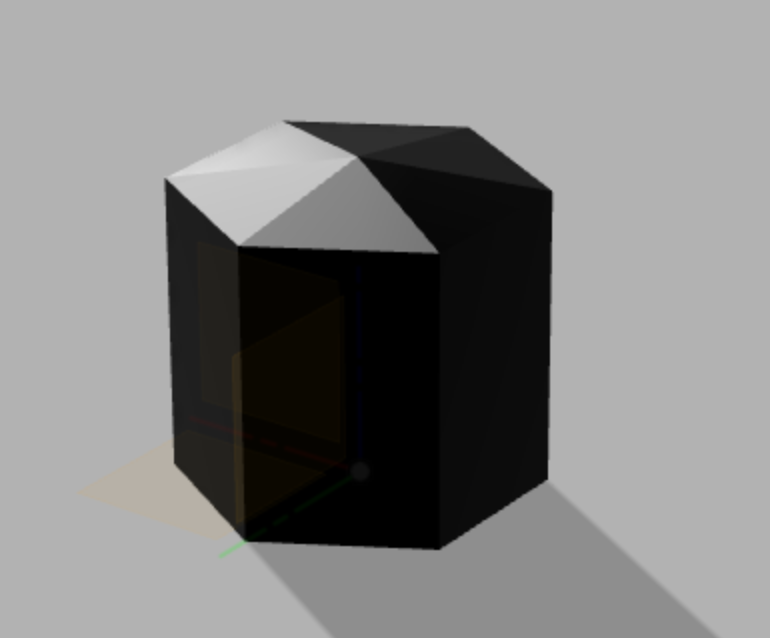
Cutting the hexagonal center piece. This isn’t too tall, so I think it can be done with the piece vertically if I can figure out workpiece holding.
#1 and #2 will probably need to be cut using a combination of ¼" and ⅛" end mills. Since I’m still on the free version of fusion, I think that means creating two separate .nc files, one for each tool, but then this means I can’t use the BitSetter to align heights, right? Or, is there some other way?
I did figure out how to import Carbide3D’s tool library, but I’m not sure it’s updating the correct feed speeds and such (it doesn’t update spindle RPM, for instance). These piece are all hard wood (softer than maple but harder than cherry), so input on tool configuration would be appreciated.
Also, help on how to proceed on the toolpaths would be appreciated. Do I do a 3D adaptive contour for the inlay cutout followed by a 3D contour finishing pass? Something else? How much material to leave after the first pass?
Just realized that I did not do the “wedge” thing for the inlays, which requires using the “V” bits, right? At this point, I think I want to just mill the pieces straight up and see what kinds of gaps I get. With contrasting woods a few thousands of a gap would be tolerable - and probably inevitable given wood movement after several years anyway.
Thanks again for all the help. I’m excited to see the components come alive in Fusion.
If your version of Fusion won’t generate a multi-tool file with M6 tool change commands, yes you’ll need to generated one nc file for each. Carbide Motion can’t utilize the BitSetter in that situation, so you could either:
re-zero manually between jobs. Of course there is the matter of not milling away the zeroing point with the first tool. On the case of that hexagonal base, and since I understood you are going to be using some kind of jig/pegs to align the base (and later rotate it), it would make sense to a) model the jig in Fusion too, and b) set the zero reference somewhere on that jig, so that it’s still accessible after any job
if you really, really wanted to use the BitSetter, you could consider using another G-code sender (CNCjs) and the associated BitSetter macros, in that setup you can run individual BitSetter probing between runs. But having to learn how to use a different G-code sender just for this may be overkill here.
What specific 1/4" and 1/8" tools are you going to use ? Feeds and speeds will depend on their number of flutes. A good starting point would be the feeds and speeds recipes in CC for hardwood, and there’s always Winston’s MaterialMonday video for wood.
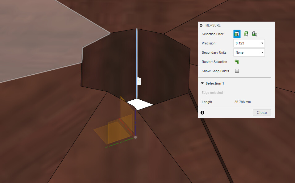
So the first thing I realized upon opening you model is that the center hexagon hole is going to be difficult to CNC:
it requires to cut through 36mm of wood, which mean that ideally you would want an endmill with a length of cut of at least that (to avoid rubbing the shaft against the walls when cutting the final passes), and most of the common 1/4" and 1/8" endmills don’t have a 36mm length of cut. You could still go ahead and do it with a smaller LOC endmill anyway, it’s a little awkward but sometimes one can pull it off. You will still need to have ~40mm of endmill sticking out of the collet
but the bigger problem is to inside corners of the hexagon. A 1/4" endmill is going to leave large rounded corners, a 1/8" endmill could make smaller corner radius but it’s going to be hard to find a 1/8" endmill with such a long reach and LOC. And that would still leave you with less-than-pointy inside corners. Maybe having the center hexagon “cap” the top of the base could allow it to have a circular lower part and a hexagonal top (but then it becomes a 2-sided milling job).
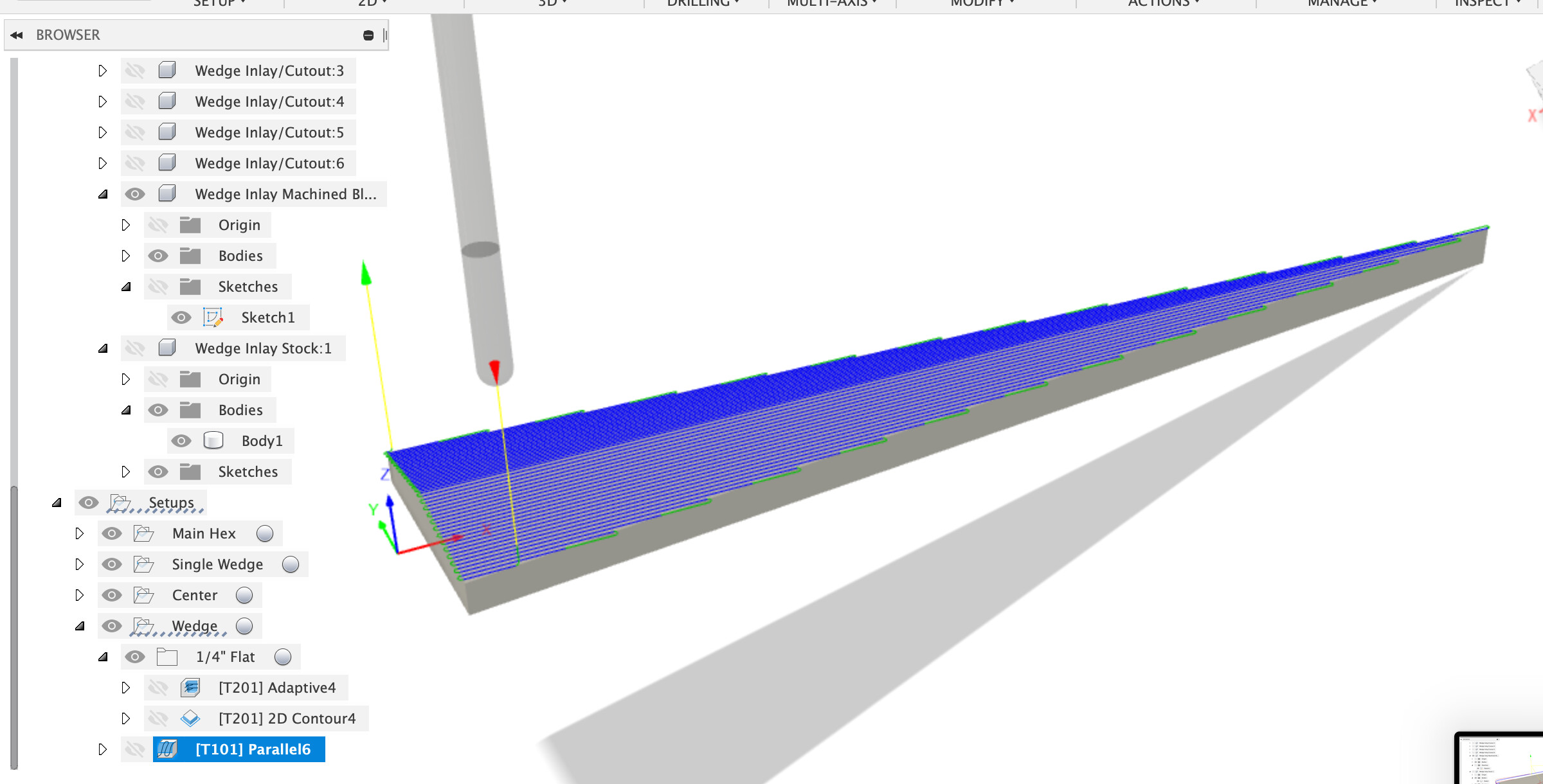
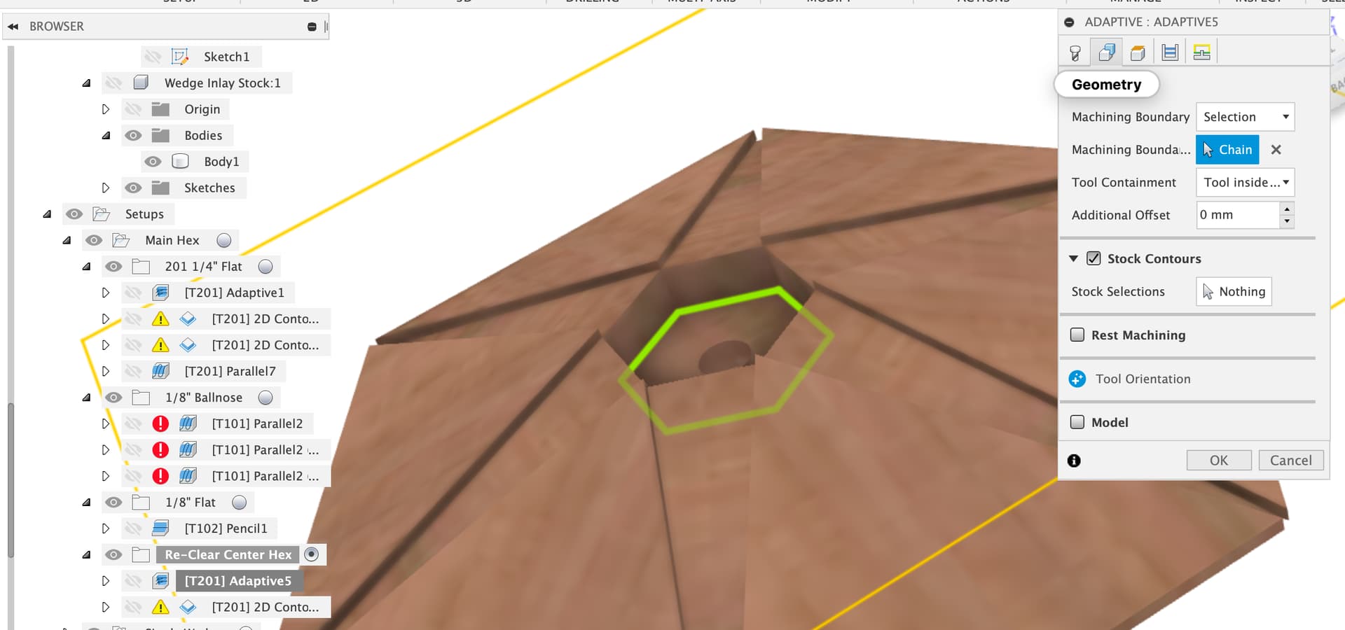
For the wedge pocket, I have not played with it for long but I wonder if you could use a “Parallel” toolpath, selecting the bottom of that pocket as the boundary, first with a 1/4" tool (tool containment = “tool inside boundary”, with some radial stock to leave:
I agree that it’s worth trying a “straight” fit first, which you should be able to pull off even if it means creeping up on the correct dimension of the wedge (which is trivial in Fusion: make the part initially oversize, cut, measure/fit, adjust “stock to leave” to a small negative value, recut, re-test, rinse and repeat until you get a perfect fit). Doing the V-bit thing in 3D brings some complications (however it may still be interesting, for a more error-tolerant perfect fit of all wedges.
On the machining front, I also took a look (as how best to machine this on a 2.5 axis machine is an interesting question).
If I was making this, and willing to mess about with 6 setups to machine each wedge pocket separately, I would probably use my table saw to create two large angle wedges to let me mount the main hexagon at an angle such that a wedge pocket was flat.
I don’t have that sort of patience though so I thought I’d try out how to machine the main hex in one setup to avoid re-zero-ing and all the risks of messing up that come with that.
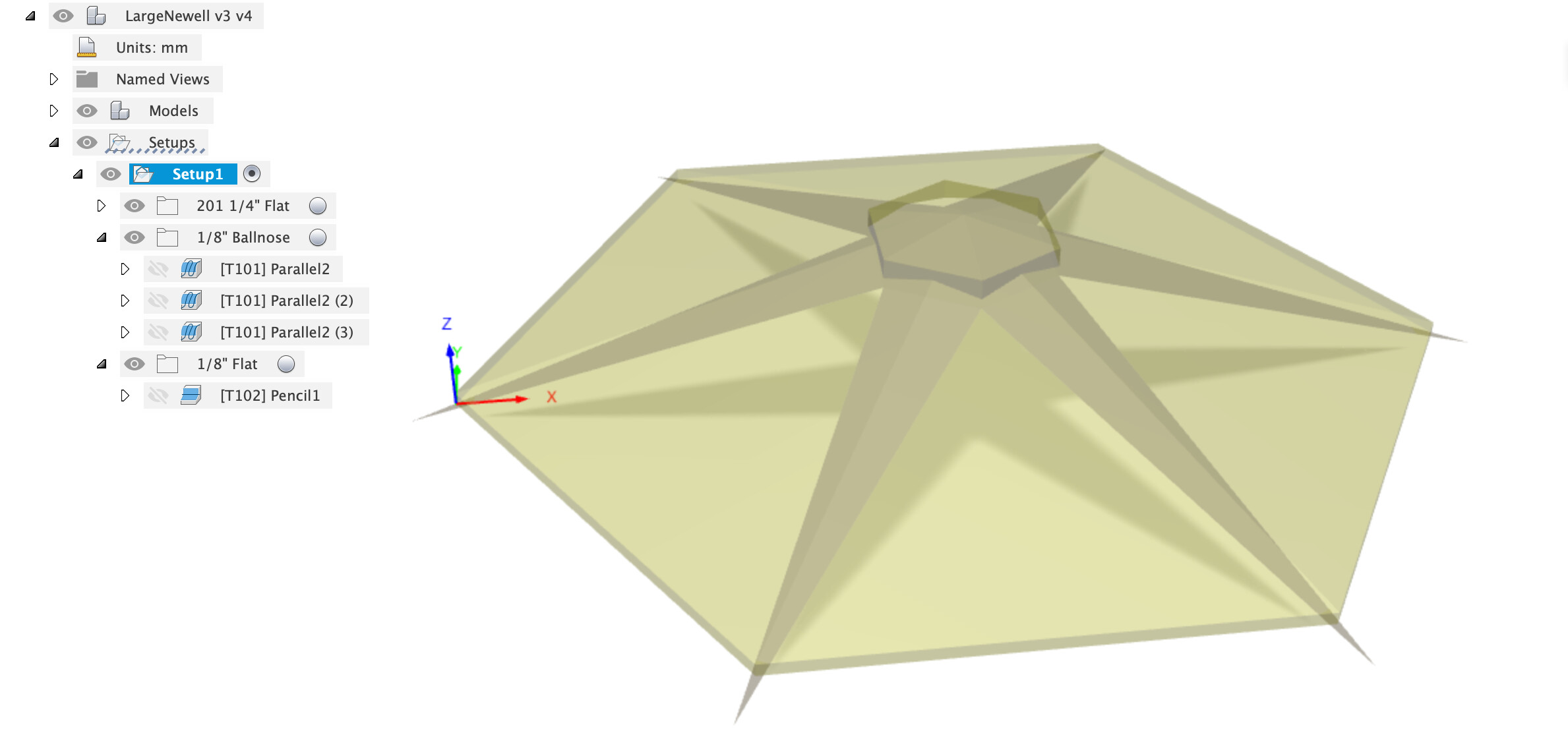
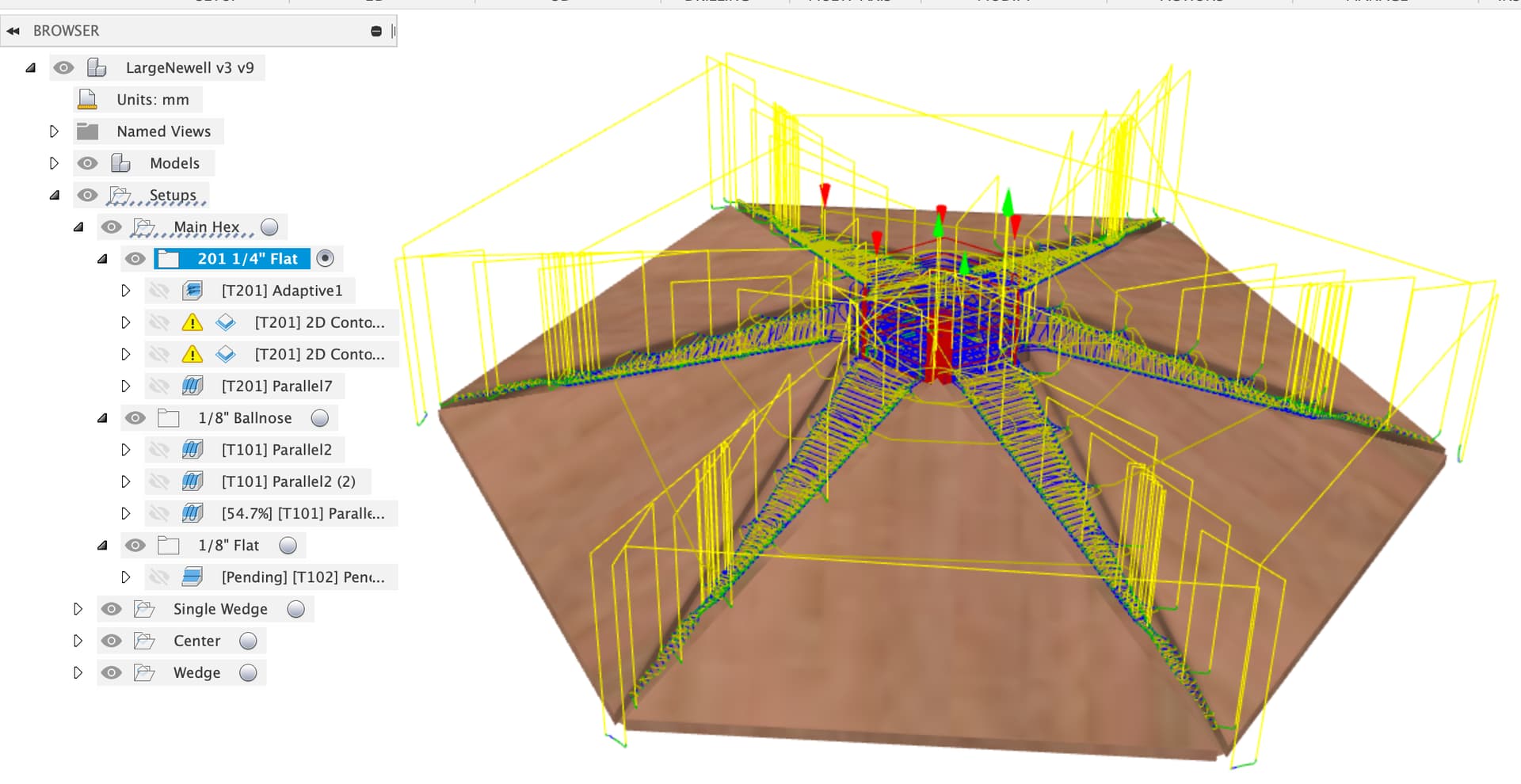
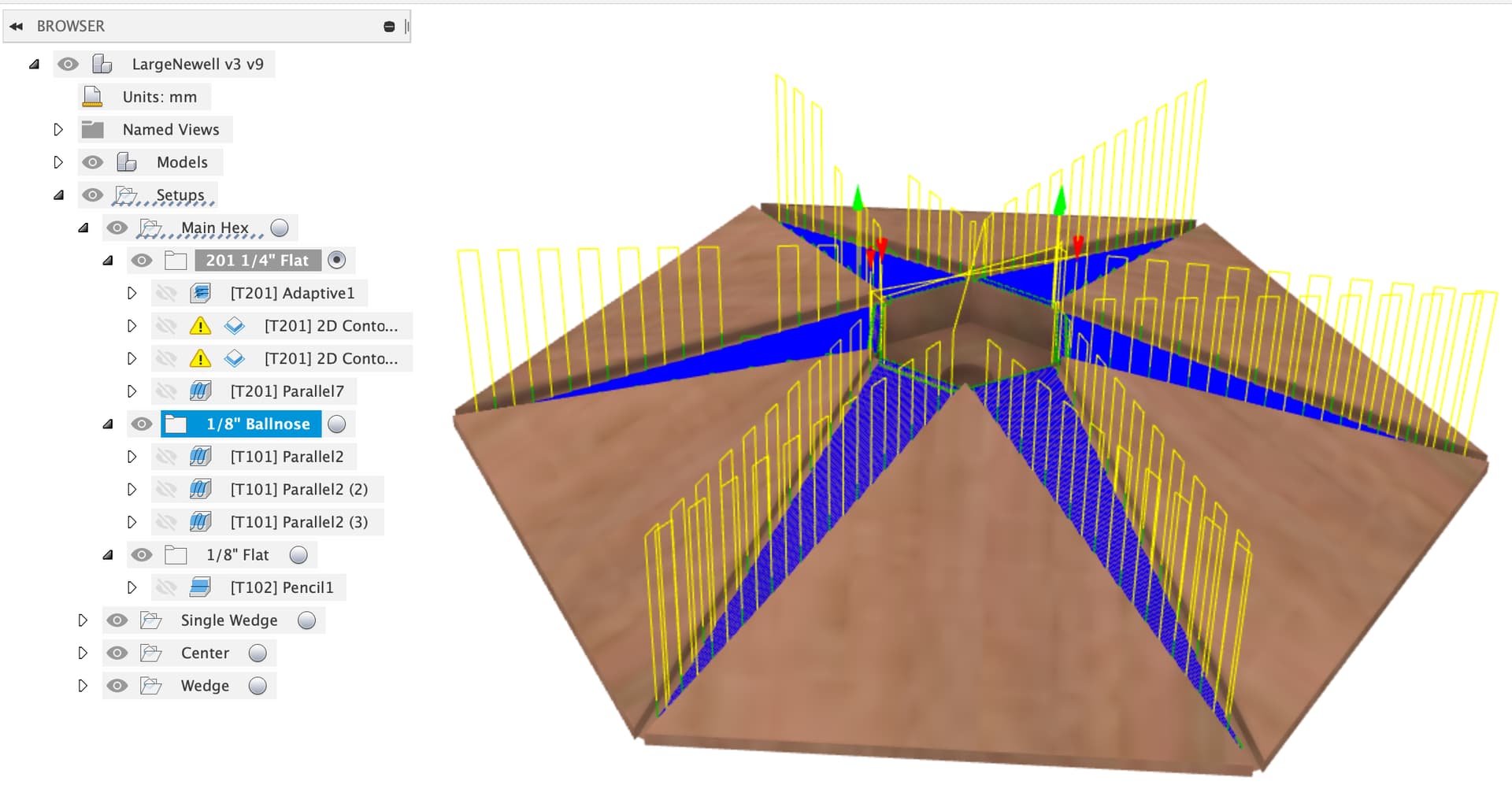
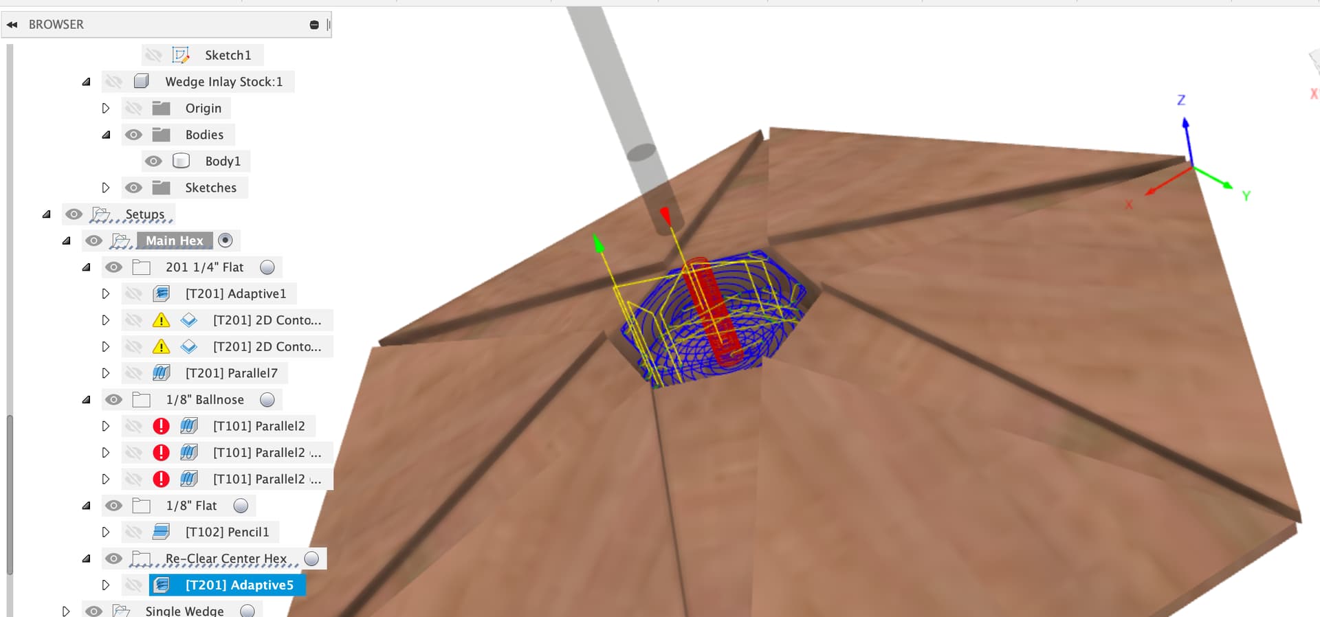
First thing was to create a stock body to use adaptive clearing against
That allows me to make one setup for the whole main hex thing which assumes the central hole and wedge slots are occupied with stock and need to be cut.
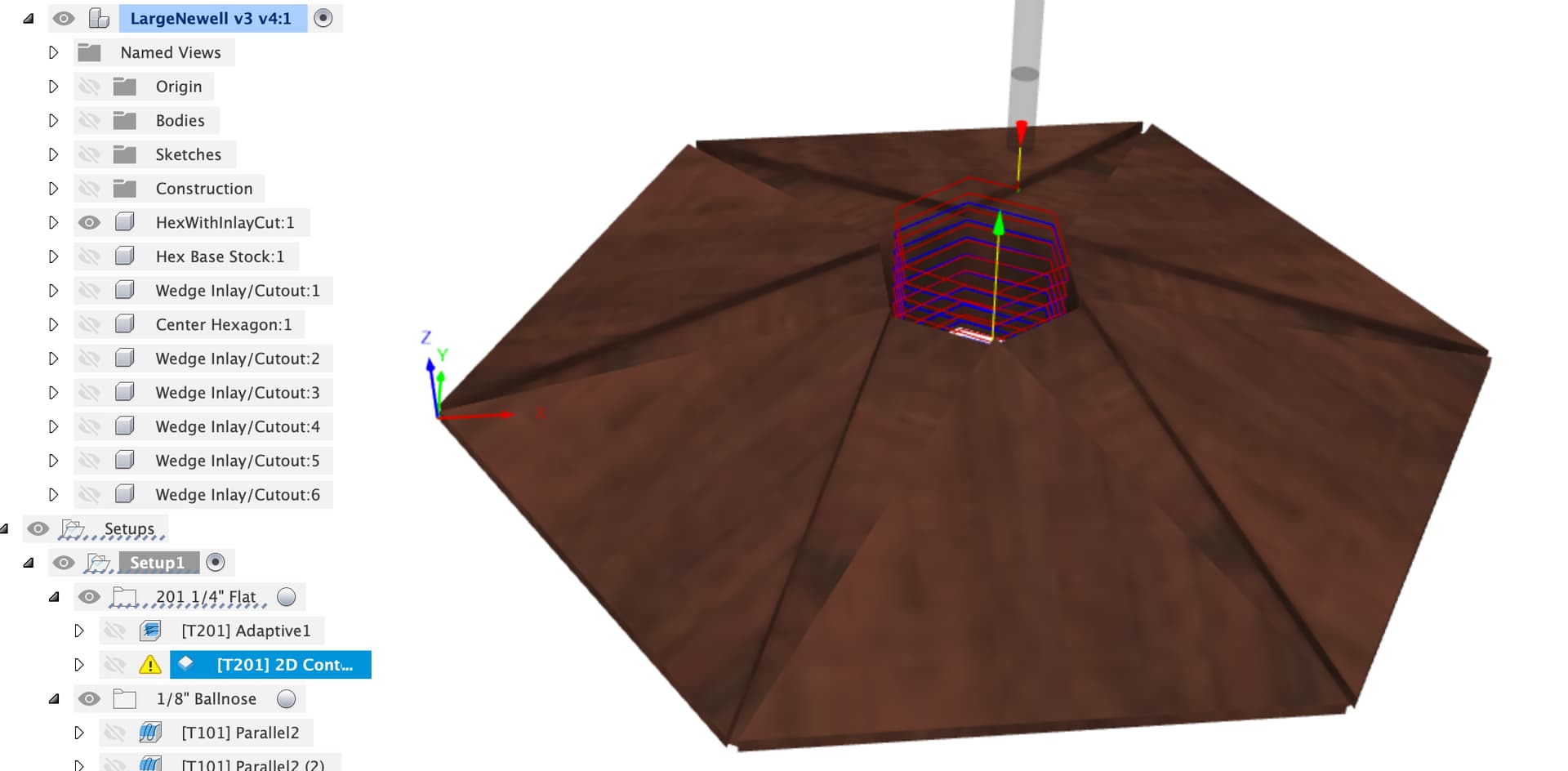
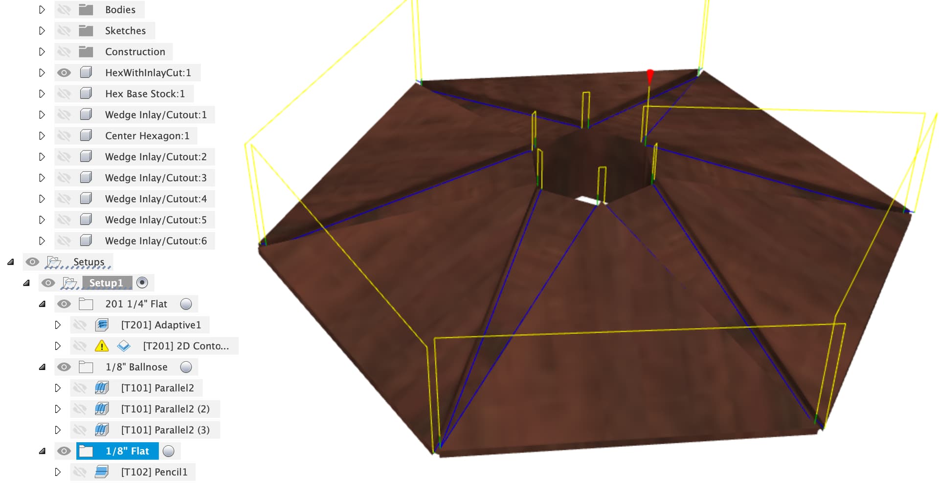
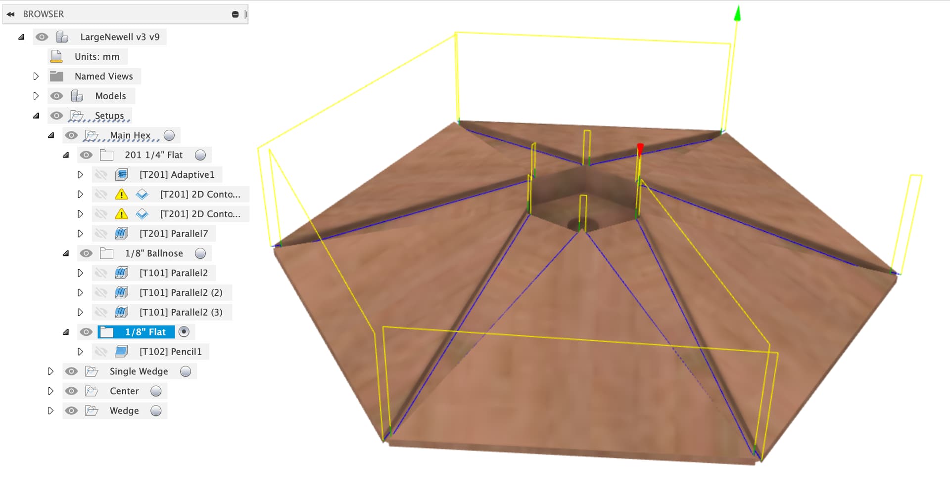
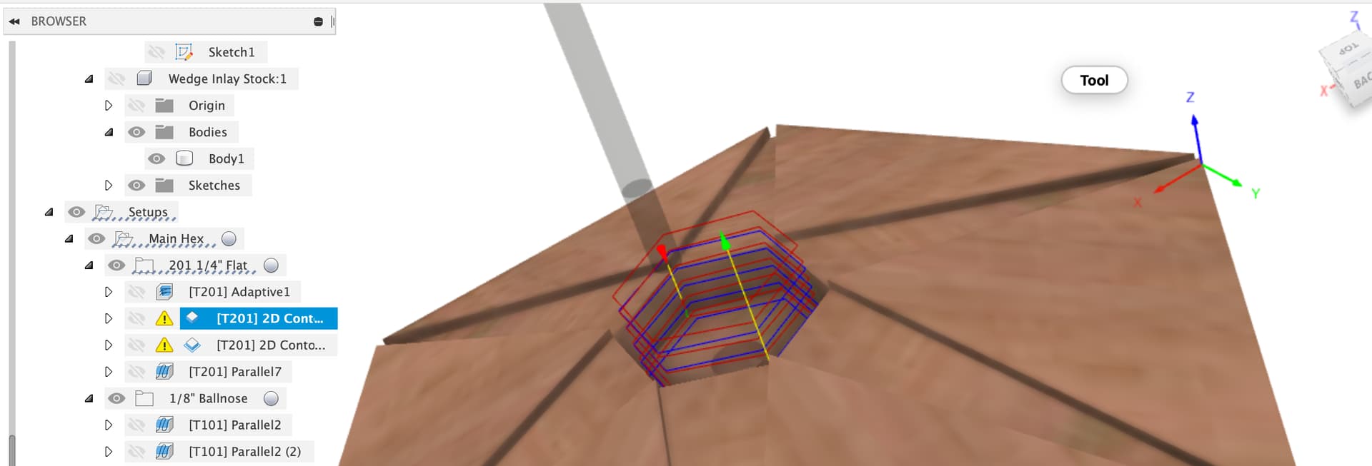
Then a 2D contour to face the central hexagon, I would just come back with a sharp chisel and square out the corners on this. I would also consider only making this hexagonal for the top 1/2" or so and then making it circular or with rounded corners, depends on how I was planning to make the central hexagon.
You could come back with the 1/8" bit and do the top 20mm or so to get squarer corners near the top to make the hand finishing with a chisel easier.
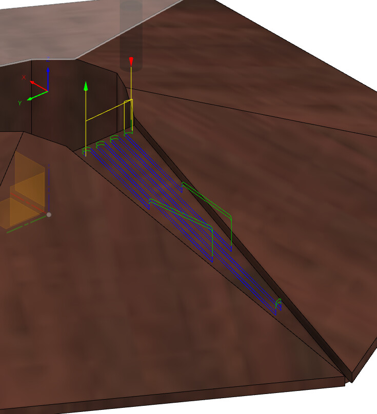
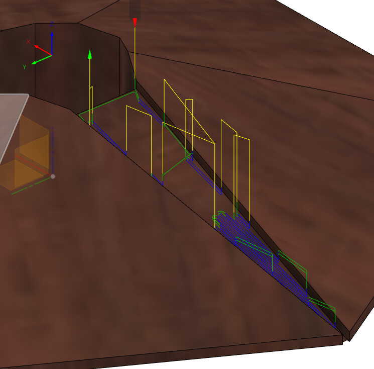
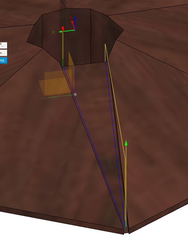
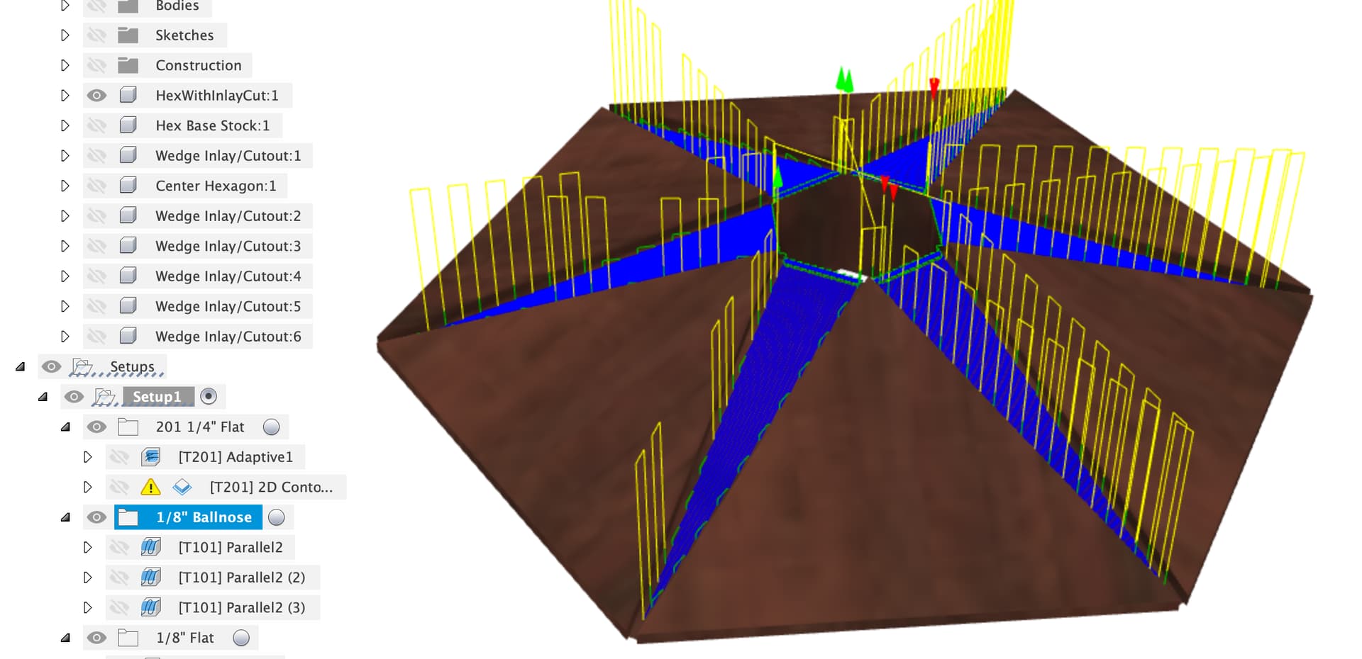
I’d then run a 1/8" ballnose to get a reasonable ‘flat’ on each of the wedge slots, 3 separate jobs here at 0, +60 and -60 degrees pass direction, 0.25mm stock to leave radial to avoid dinging the walls.
Finally I’d come back with a pencil toolpath to clean up the edges, note that even the 1/8" is too fat for the ends of the slots so those are likely manual with a chisel too. I might leave the outer edges with extra stock to control breakout whilst machining and do a final finish with a plane or table saw.
For the wedge inlay I would run a contour (or just use a table saw to cut the wedges to fit) around the edges and then an adaptive clear on the top with at least 0.5mm stock to leave, glue them in and then use a plane / sander to flatten them flush with the hexagon.
WOW, Julien and Liam - I’m still digesting, but I am most appreciative.
My first note is that because these sit on top of hexagonal posts that themselves aren’t perfect (off by more than 1/16"), my thought was to not mill the whole thing in one setup. My idea was to build the base without wedges, trimming the sides manually as needed to fit the posts and then beveling on the tablesaw. I’d then screw two pieces to the spoilboard to “capture” one of the points, which act as registration for the wedge inlay cuts. The “zero” point would be fixed relative to the registration pieces and so would not change for each inlay cut once set up.
The base shouldn’t be from one piece of wood since then the grain wouldn’t run the way it needs to (which is parallel to the outside edges for both appearance and wood movement purposes). A 10" wide board will expand and contract a lot with humidity changes. I really do think I need to glue six pieces to construct the base. My cuts don’t have to be perfect since the wedge inlays cover all those base joints.
I discarded the “angle the base so the inlay is horizontal” idea because of the imperfect nature of the base would literally required shimming each cut to get it perfectly horizontal, and then also require re-zeroing for each.
The points you both made about the center hexagon are spot on - sorry I didn’t disclaim that aspect, which I didn’t do because that’s not my focus. I was planning on something similar to Liam’s idea of cutting just a tad deeper than the center piece is visible for, and glueing it in. I could use a screw from the bottom of dowel it, but it’s not load bearing and there’s lots of surface area so glue should be fine. Slightly rounding the center piece so it fits the 1/16" radius corners from the ⅛" bit is probably the right way to go from both fit and feel to the hand as you climb the stairs perspectives.
I’d want to cut the center hexagon cut-out after the wedges are glued in place, rather than try to make those perfect from the get-go. This way I can cut the wedges longer and simply slide them into place as far as they need to go, knowing that my subsequent milling operation will trim off any excess.
I’m really worried about re-zeroing with all the bit changes. Autodesk offers a 30 day free trial, so I’m thinking of doing that for this project. I could then decide whether I want to buy a year subscription, or maybe even just do a month whenever I really need it.
Yes, as Liam noted, the tight end of the wedge is smaller than ⅛" so I’d have to use a chisel or small dovetail saw to finish the cut-out.
I had thought about leaving more base material, cutting and inserting the wedges, then trimming to fit the posts, but since the wedges taper to that narrow < ⅛" dimension, one’s eye would see any deviation. This is why I think I need to cut the wedge inlays after getting the base to overall dimension, and indexing from the “point”, since that’s the critical dimension.
Which makes me realize there’s another critical dimension here where the wedges meet the center hexagon. So I think need to mill the center cut-out before trimming the base to fit the imperfect posts, and then cut the wedge inlay, and then trim the fat inside part of the wedges to match the center cut-out.
And now the most important part. Thanks for sending your modified Fusion 360 files back to me. I’ve been struggling with toolpaths in Fusion and don’t understand many of the parameters or what to do. Hopefully I can make sense of what you’ve sent back.
I have the Carbide3D starter set of bits: #201: ¼" end mill for stock removal #102: ⅛" end mill (½" LOC) for corners #202 & #101 ballnose mills (¼" & ⅛") #251 ¼" spiral downcut (which I don’t think I need for this job) #301 & #302 V-cutters (also not needed)
I also have a collection of router bits from my normal woodworking activities.
WRT Fusion, there is the free hobbyist license which I use, if you’re not using it professionally.
As for re-zero-ing between bit changes I leave the workpiece in place so the X and Y don’t change and always zero the Z off the spoilboard so it’s easy to re-zero after a bit change.
As for cut order and doing the inner hexagon afterwards, that’s all just down to the order you do the toolpaths, the payback for the CAM being a bit dumb and needing lots of guidance is you can make it do almost anything you like.
One thing I’d suggest is, given that you want to machine thing which is not regularly shaped, to think carefully about where you can set the X, Y, Z zero for each setup and have them align reasonably at the center etc. There’s a decent risk of things being visibly not well aligned when you get to the hexagonal center otherwise. Setting zero reliably across a multi-setup job is one of the hardest things to learn.
One option might be to put a center hole through the newell to allow you to locate on a pin in the spoilboard as X, Y zero and then just rotate newell to set the angle to match that side. Or that might not work at all, I’m not quite sure which parts of your process will be irregular.
Anyway, if you get stuck on the toolpaths, here’s a crib sheet
think carefully about where you can set the X, Y, Z zero for each setup and have them align reasonably at the center
That’s a really good point. I had planned on using the outside “point” of the wedge (where 2 sides of the base hexagon meet) as the zero point for cutting the wedge inlay, but you’re right that this could create problems at the center.
It would be simpler if I could just mill the whole thing accurately on the Shapeoko and at least it would all be aligned. Maybe I should build the topper a bit larger than the post, and have a ⅛" gap between it and the post. I could then have the overhang be the same all around, just that the centers wouldn’t align, which one couldn’t tell anyway.
In terms of my irregular post, each side is supposed to be 5" across (hexagon inscribed in a 5" radius circle), but in actuality some sides are 1/32" or more shorter while some are the same amount longer, and some are pretty close. Just looking at the post, it seems fine and if I did a simpler topper design it wouldn’t matter, but I’m kind of proud of this and want to see it through.
Thanks again for all the tips and techniques, and advice! This is a great community!
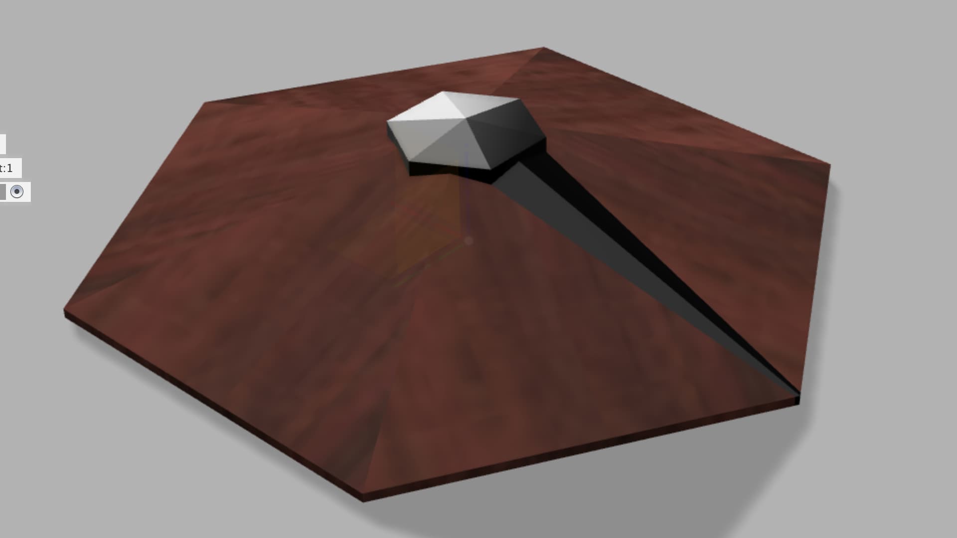
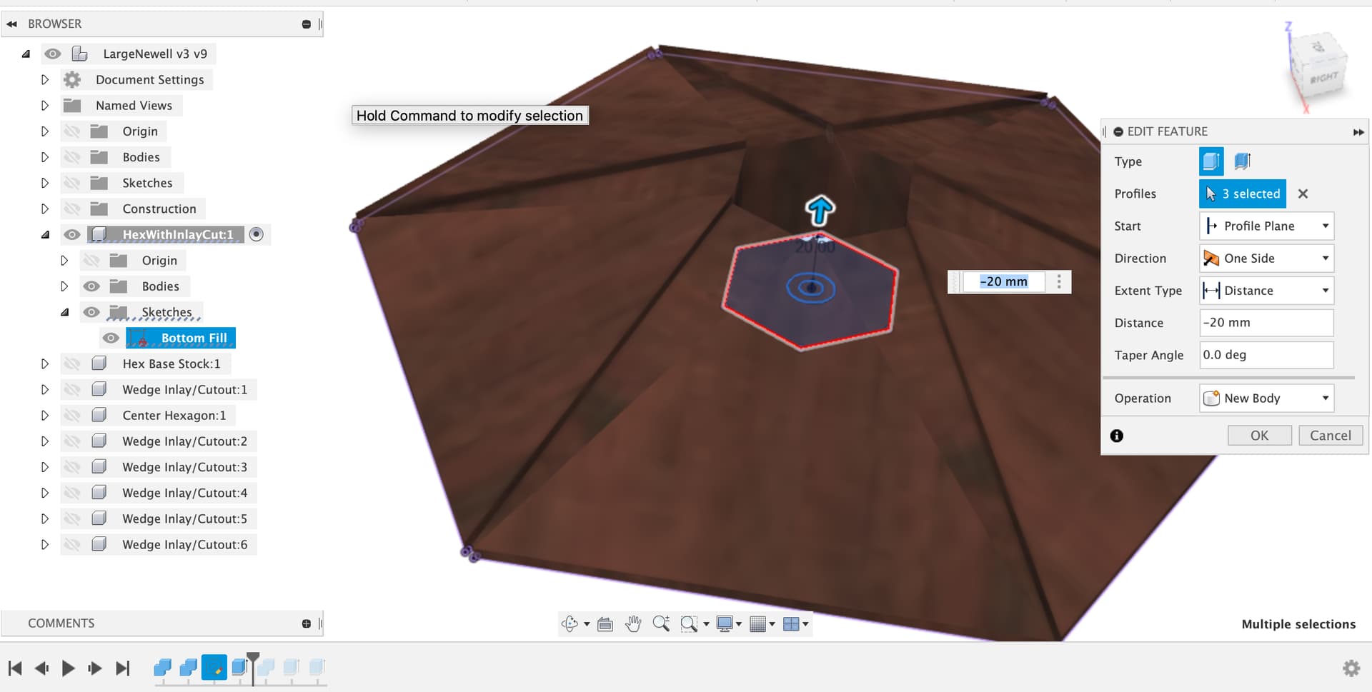
Liam, I’m going to try to build the thing via your idea of doing it all on the Shapeoko. I’m taking your v5 file, but I need to change the center hole so it doesn’t go all the way through. Not sure how to do this without messing things up.
I can push/pull the bottom of “Center Hexagon:1” up as high as I want (a delta of -32mm seems about right to me). That’s the easy part.
But the “HexWithInlayCut:1” component still has the hole going all the way through. How do I fix that?
What I’m doing for the try-out is gluing two pieces of MDF together to get the 38mm thickness. Then I’ll cut out the triangles and glue them up just as if they’re real wood (yeah, I know I could just start with a single piece of MDF that big, but I want to mimick as many of the actual steps as possible on this trial run before committing it in the exotic woods).
Once I have the hexgonal base glued, I’ll want to mill the center hexagonal pocket and 6 wedge inlay pockets. This is what I’m most concerned about doing on the Shapeoko.
Then I can explore cutting the wedges and center hexagon on the Shapeoko. On interesting thing is that if I cut the center hexagon on the Shapeoko, I can design it with 1/16" radius rounded corners to match the pocket. Liam, are there toolpaths in the file you sent that will do that, or do I have to somehow derive those?
I’m going to owe you more than a beer when this is done!
Yes, that would be a smart way to go about testing out your toolpaths, I generally brutally murder some old plywood or MDF testing toolpaths before letting the real wood go for surgery
There’s a bunch of stuff to learn to get right here from zeroing to ensuring the machine is fully square, that your belt tensions are even and your X, Y are calibrated close enough to each other etc.
Be aware, the speeds and feeds selected on these toolpaths are about what I run on my machine, subject to my ears telling me to reduce feedrate or change the DoC or similar in the CAM and re-run, don’t just expect they’ll all be good for your stock on your machine
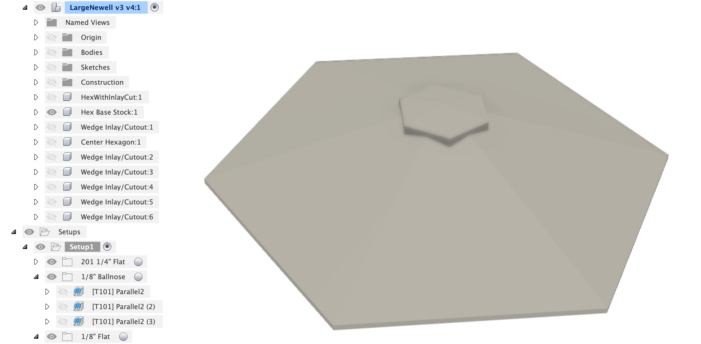
OK, this is quite easy, once you think in the boolean and sketch verbs that Fusion gives you. There’s lots of ways, here is one.
Hint - Use the timeline at the bottom of fusion to replay the actions somebody took to build or modify the Fusion file, it lets you see their steps and figure out the order in which they did things. If you select a component the timeline only shows actions for that component, if you select the root “LargeNewell v3 …” then you see the timeline for everything.
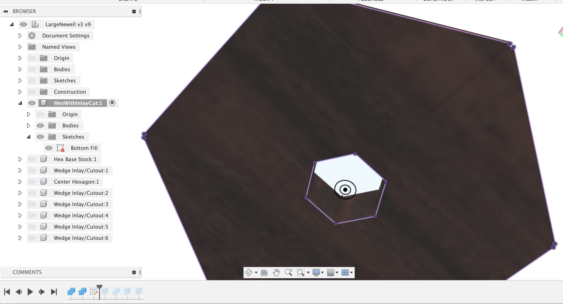
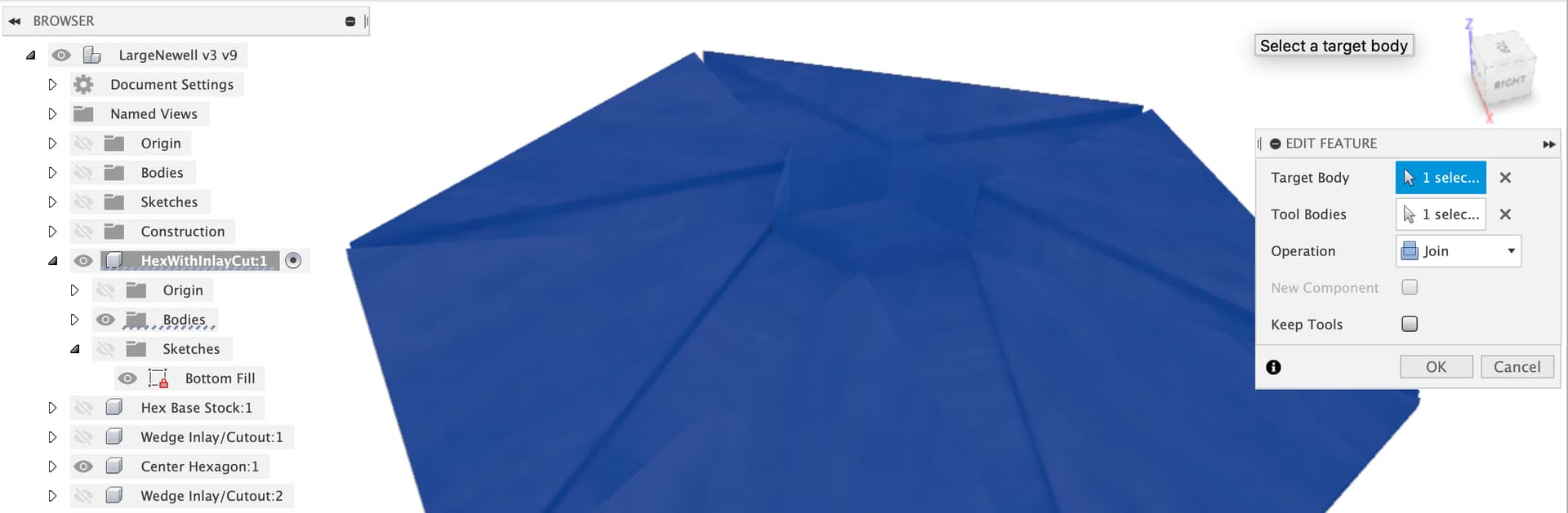
Make a sketch on the base of your main hexagon and project (P) the outline of the hexagon into the sketch.
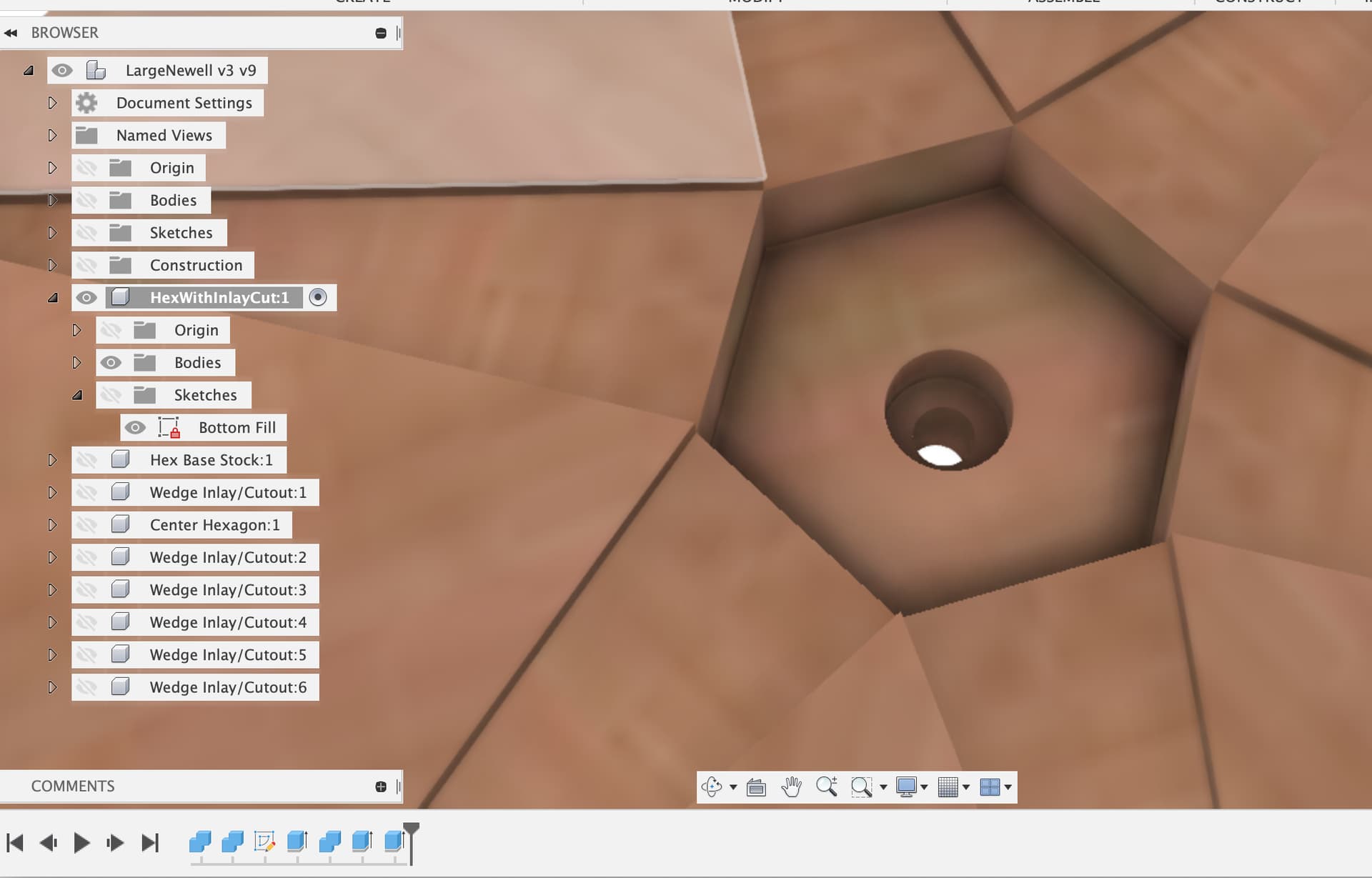
So now we have a main hexagon with no hole in the bottom. Next I used the combine feature to cut the bottom off the Center Hexagon using the newly filled in part of the HexWithInlayCut
It occurred to me it might be useful for zero-ing and also for attaching to the post to have a bolt / screw hole right in the center, so I extruded those too, just delete those two extrudes from the history to remove them.
Now onto the tricky bit, the insert wedge, this has an undercut where it meets the central hexagon and also needs to be a really clean fit into the wedge slot machined in the hexagon and then has to be flush with the surface.
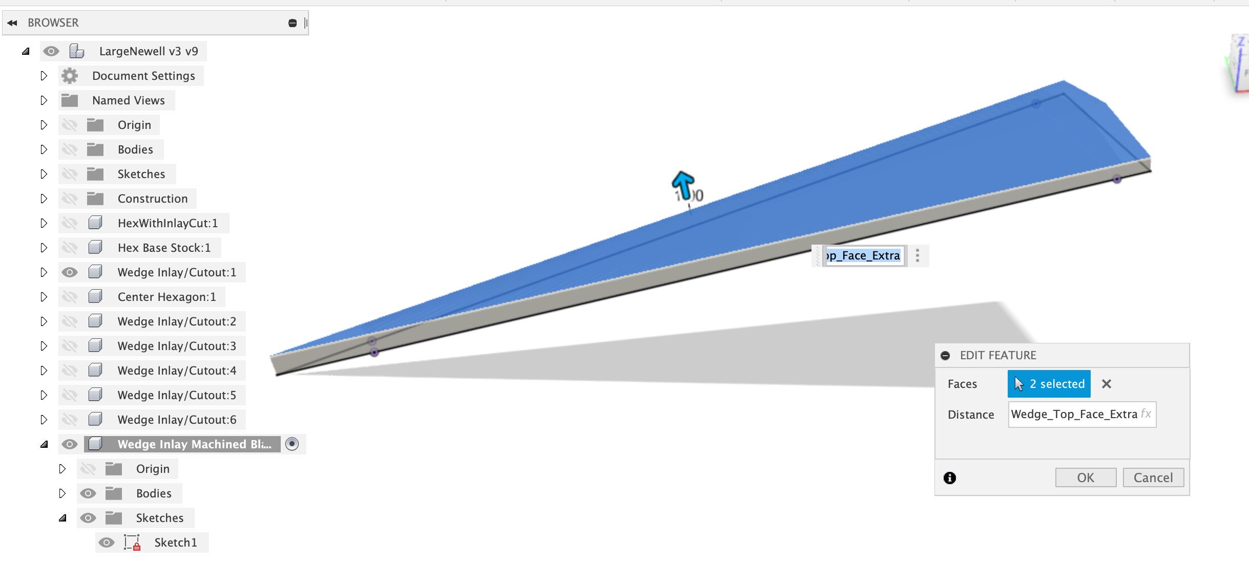
My suggestion (awaiting better ideas from the more experienced woodworkers here) is to cut this over length and over height so that you can push it into the slot until it ‘bottoms out’ on the walls and rear face then trim the ends and finally face the surface down (with a plane or sander).
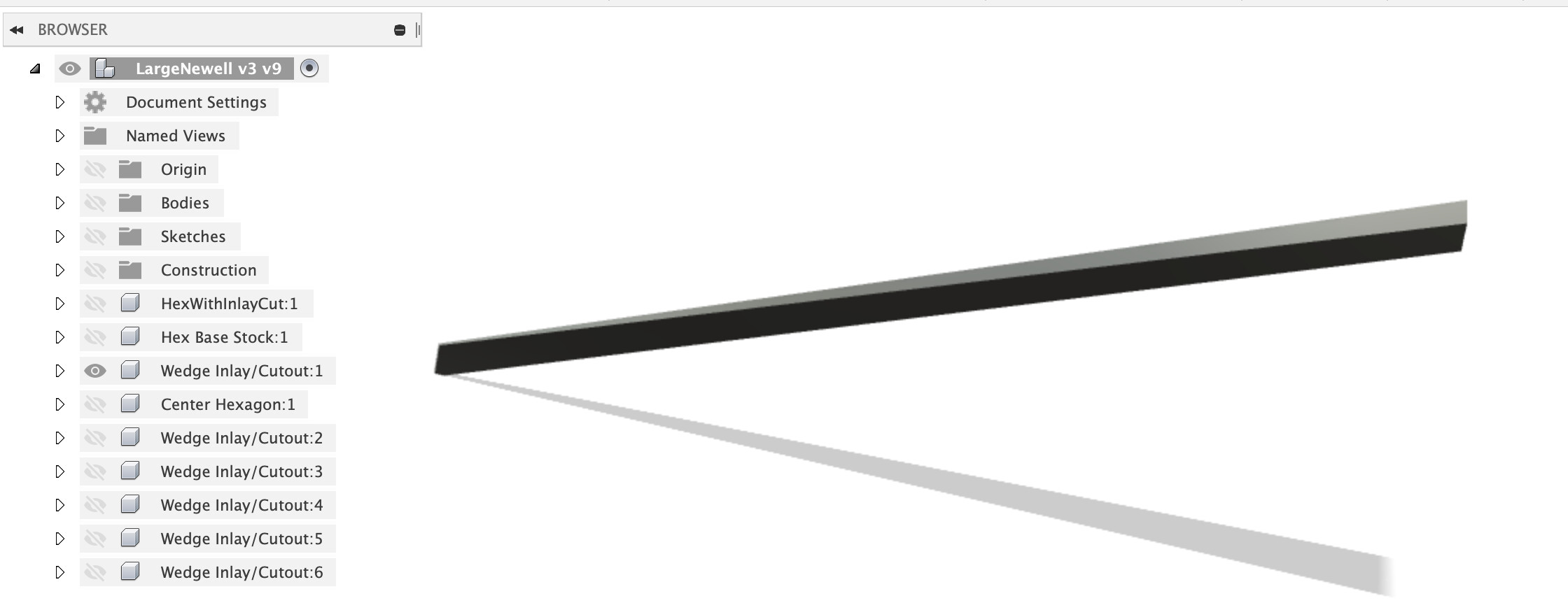
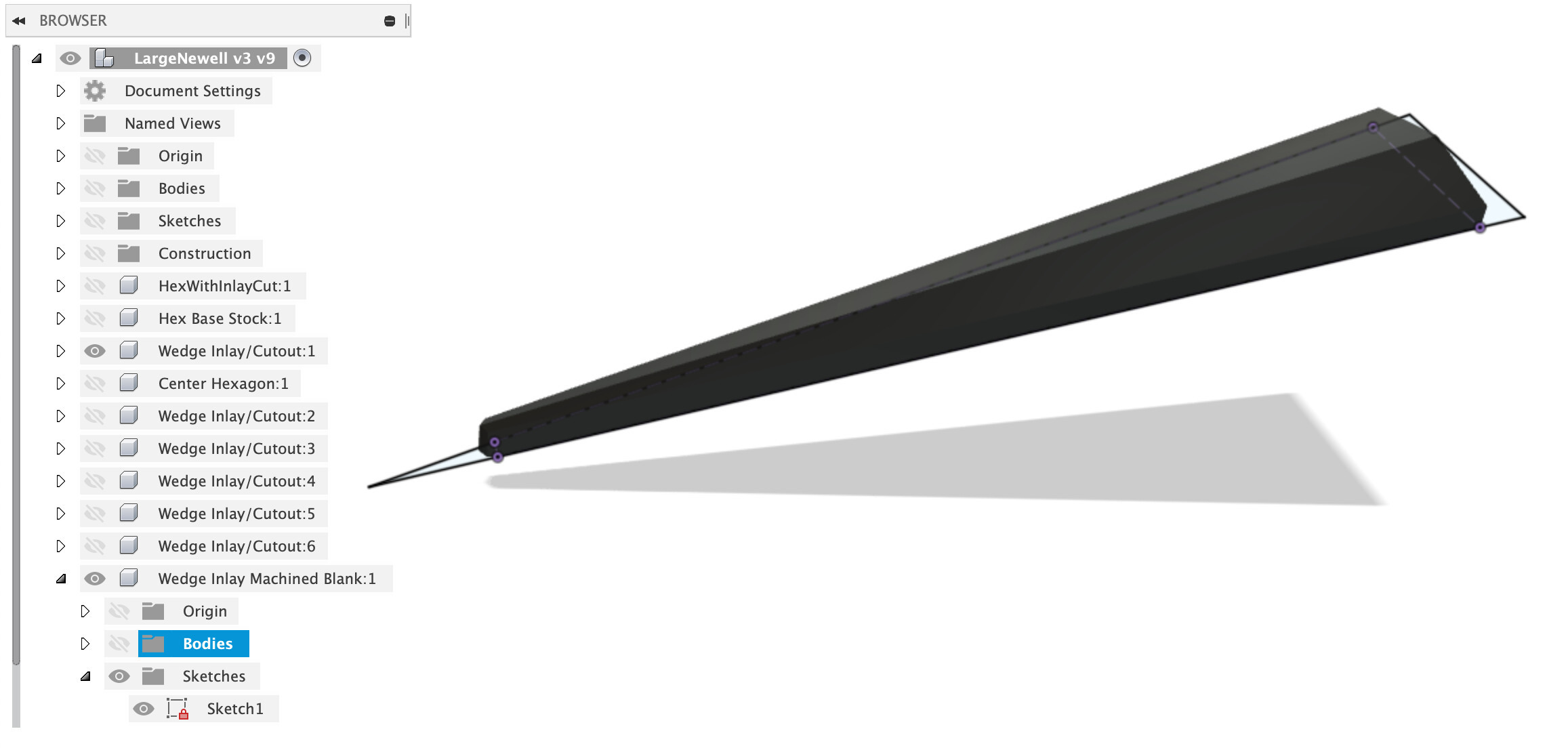
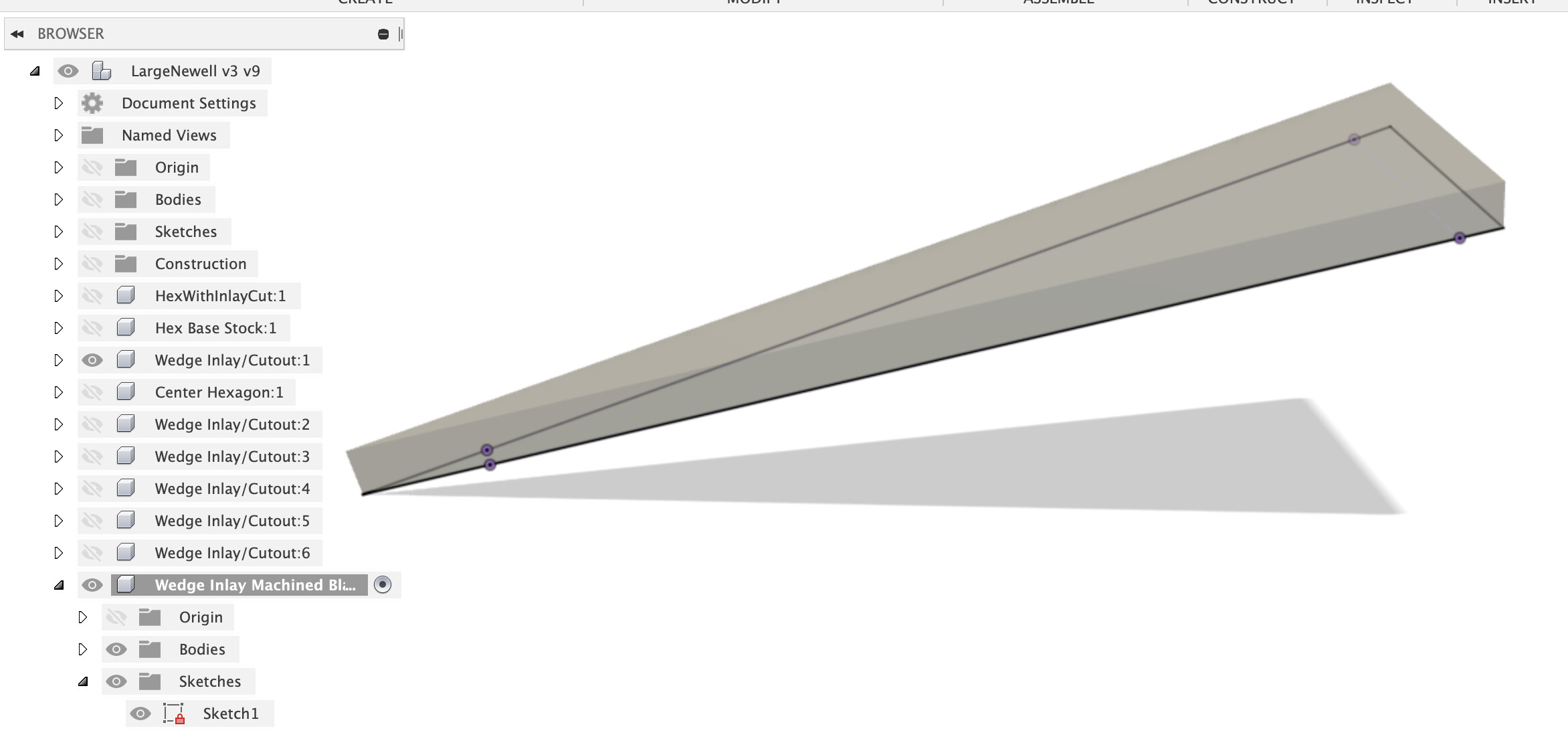
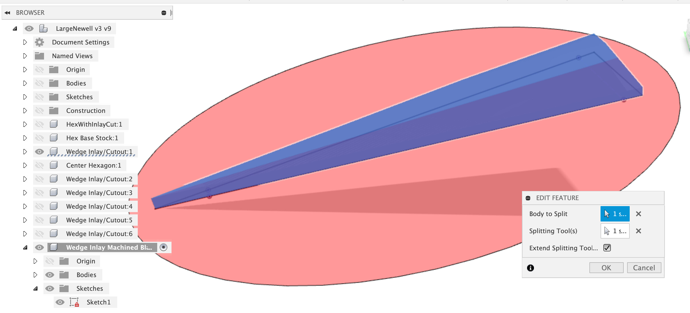
I created a new component to give us this larger body to glue and trim in place. In this new component I created a sketch on the bottom face of your existing wedge, projected the outline of the wedge and then extended the sides forward and backward to give some extra to cut off later.
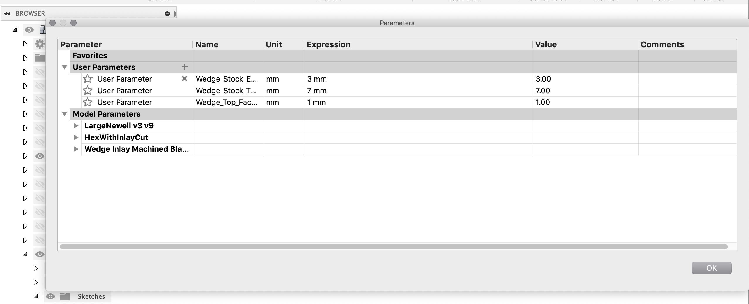
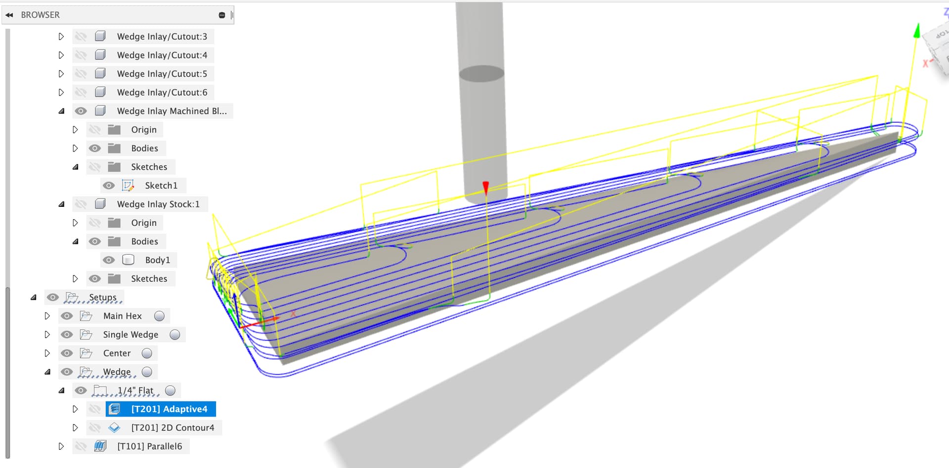
Then I made another new component for the stock, no idea how you plan to prep the stock so I just made a wedge that was a bit bigger (user params again). Same trick, sketch on the base of the Wedge Inlay Machined Blank, project, add extra, extrude thicker.
Then a new machining setup for the wedge using the stock body for stock, note the choice of zero location, may or may not be what you want depending on how you prep the stock.
I’ve assumed blue tape and superglue workholding here as clamping this stock would be a pain and need tabs and other complexities, that’s all up to your preferences…
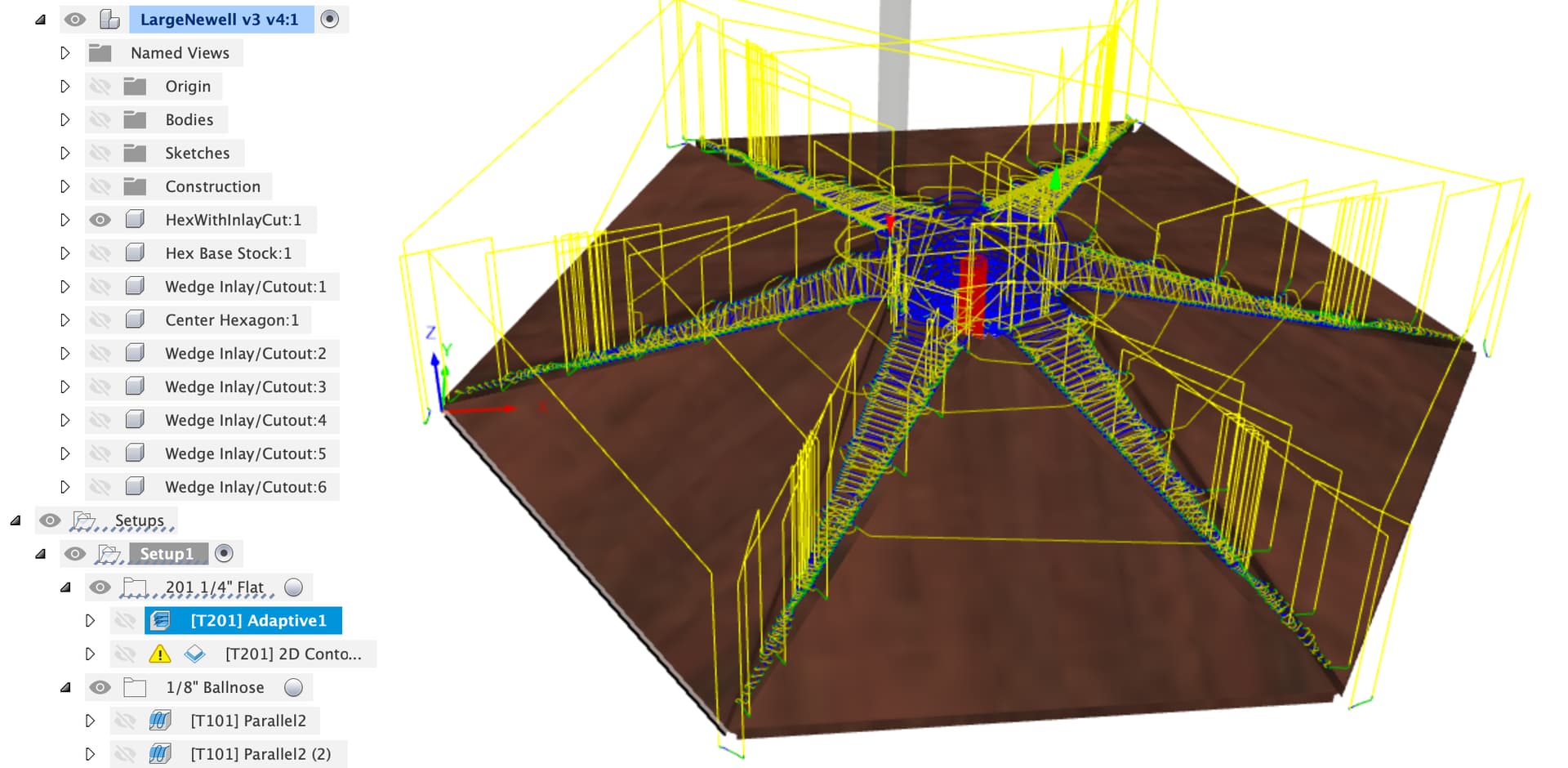
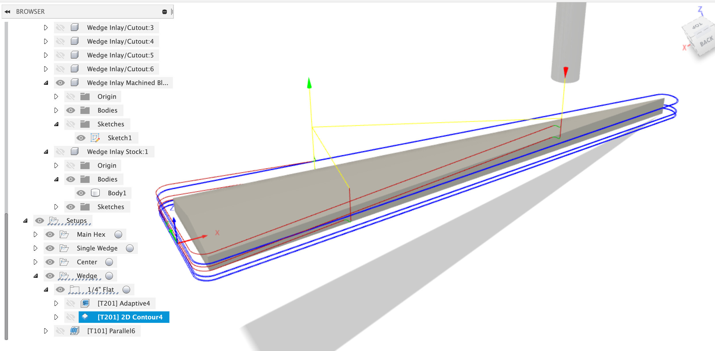
First is a 3D adaptive toolpath with the 201 1/4" cutter, then a contour around the edges, this is where you find out if your Shapeoko is square and whether your X, Y calibration is good.
Finally an optional 1/8" ballnose to trim the top surface down, not sure this is really useful as you’re going to plane / sand this down to flush with the main hex once glued into place.
Beware, you will need to get the workpiece zero exactly the same for this, you might be better off not cutting the center hex at all in the first machining and only cutting it once in this step. Try it out and see.
Yep, using the same 2D contour toolpaths in the main hex with smaller radius bits will get you a smaller corner radius.
As for the central hex, try it out, make a stock component of the blank you want to machine from and then try a setup using your stock component to do stock “from body” and then the adaptive clear, followed by an outer contour and probably parallel over the top with a ballnose?
Wow again - will take a look later today after I get the parts in glue-up. Some overnight thoughts:
I was also thinking about hold-down options. My post is hollow, so a center hole won’t help there, but now that the center hex cut-out is a shallow pocket, I could easily drill a center hole manually and screw that into a T-nut in the track of my hybrid table. I could also “add” the tape/superglue around the edges for additional security. For cutting the wedges themselves, definitely need the tape/glue. For the center hex, since it’ll be standing up, I’ll probably screw a piece of plywood to the bottom and then clamp the plywood to the hybrid table.
I’m thinking the new center point should be the bottom center of the main hex body. I would do this in two stages: first I’d set the Z-axis to zero at the spoilboard, or maybe a piece of paper higher. Then I’d mount the blank and zero X-Y at a pre-marked center at the top. I don’t want to zero at the top since I don’t want to have the stock thickness be a critical dimension for me to achieve.
Routing away all that material for the main bevel seems like a waste of time, router bit wear, and dust bag. I should probably cut a rough bevel using the tablesaw - just keep it say 1/8"-3/16" away from the final surface. This means modeling the original stock to have that bevel. I’d probably model the stock to be slightly larger than I expect to manually cut the bevel and live with the tool spinning in space for a couple rounds.
You wrote: My suggestion (awaiting better ideas from the more experienced woodworkers here) is to cut this over length and over height so that you can push it into the slot until it ‘bottoms out’ on the walls and rear face then trim the ends and finally face the surface down (with a plane or sander).
Yes, this is exactly my intention, although since an extended “rear face” is in the hexagonal pocket, my thinking was that I’d do all the milling, then, leaving the base attached to the spoilboard, glue in every other wedge, letting the rear ends stick into the hex pocket (if I did adjacent wedges they’d interfere with each other in the pocket), and then, when dry, re-cutting the hex pocket. Then do the remaining wedges, and re-cut the pocket once more. There might be some hand trimming of the wedges in the corners due to the 1/16" radius from the ⅛" end mill.
I started another thread in the Shapeoko Pro category (Squaring and Calibration of Shapeoko Pro - #8 by greg5 ) for my machine setup adventures. I need to re-run the procedure again for the $100/$101 factors, but I think the squareness I’ve got is pretty decent (when gantry is slid forward there’s a 0.006" gap agains the end plate on one side, which is across 20" or more). I might try to re-square, but the only way I’d get better is to loosen not just all the bolts (and with the hybrid table there are a lot, but also loosen the belts (which I didn’t do last time).
A good starting point would be the feeds and speeds recipes in CC for hardwood, and there’s always Winston’s MaterialMonday video for wood .
OK, watched that. Winston’s great at many things, but apparently spreadsheets aren’t his strongest suit. Here’s my version of his data: Feeds And Speeds For CNC.xlsx.zip (7.6 KB) which I find a more logical lay-out.
One question I have is why both the ⅛" and ¼" cutters are run at the same rpm? Traditionally, woodworkers slow down the rpm for larger cutters. I know the desired result of how much wood each mill cutting edge takes per revolution is affected by rpm, DOC, and feed rate, but since we’re setting all those, why not choose optimum rpms for the bit cutting diameter and number of flutes and then calculate DOC/feed rates?
This has been debated here a few times, and basically the conclusion always is that while surface speed matters for metalheads (and even then, mostly for those who cut something more challenging than aluminium), for wood and given the endmills typically used on a Shapeoko (nothing larger than 1/4" in 99.9% of the cases), surface speed does not really matter. Or we could say that wood is tolerant to a very wide range of surface speeds (as long as the chipload is in check)
So for RPM as far as I am concerned it boils down to “set the RPM to the highest value you can bear”. @gmack once taught me that maximizing RPM minimizes cutting forces, so maxed out RPM should be the target. But I also used to have a trim router on my machine, and could not bear the screaming sound of a Makita at 30.000RPM for very long.
DOC is a different beast, and there was not much beyond experimentation to determine what’s a good value on a Shapeoko. Folks who know their deflection math concluded that shallow DOC and fast feedrates work better on a Shapeoko than deep DOC and slower feedrates. I like to use the “50% of the cutter diameter” rule on my Shapeoko. I hear the lucky SO Pro owners get to go deeper than that.
If you can’t sleep at night, here’s a thread where we discussed the matter of how to determine feeds and speeds on a Shapeoko (spoiler alert: there is of course no definitive answer, but that thread is basically where the stuff in the ebook’s feeds and speeds chapter comes from)
That all sounds sensible, I’ve never said “dang, I wish my workpiece was moving around more whilst I cut it”
It’s worth thinking about what happens after you machine that zero point away at the top (unless you adjust the toolpaths to leave the central portion of the hex untouched. Otherwise when you turn the machine on after leaving all the glue to dry you may not have workpiece zero any more.
Setting Z off the spoilboard is the sanity preserving option in my experience.
Sounds sensible, as you get better at CAM you’ll do more work to avoid ‘air cutting’ above the workpiece but that’s optimisation for later.
Again, sound sensible.
I might set the radial stock to leave to 1mm on the first big adaptive clear and then not run the 2D contour finishing passes on the inner hex at all until this stage to make sure if there’s any work zero offset there’s spare stock.
Sounds like you have the machine pretty square, time to cut things and see how it works. It’s never the problems you plan for that get you