Ugh. Power went out for over 36 hours, so I didn’t get much done. But, since this is obviously an odyssey, I decided to document my steps.
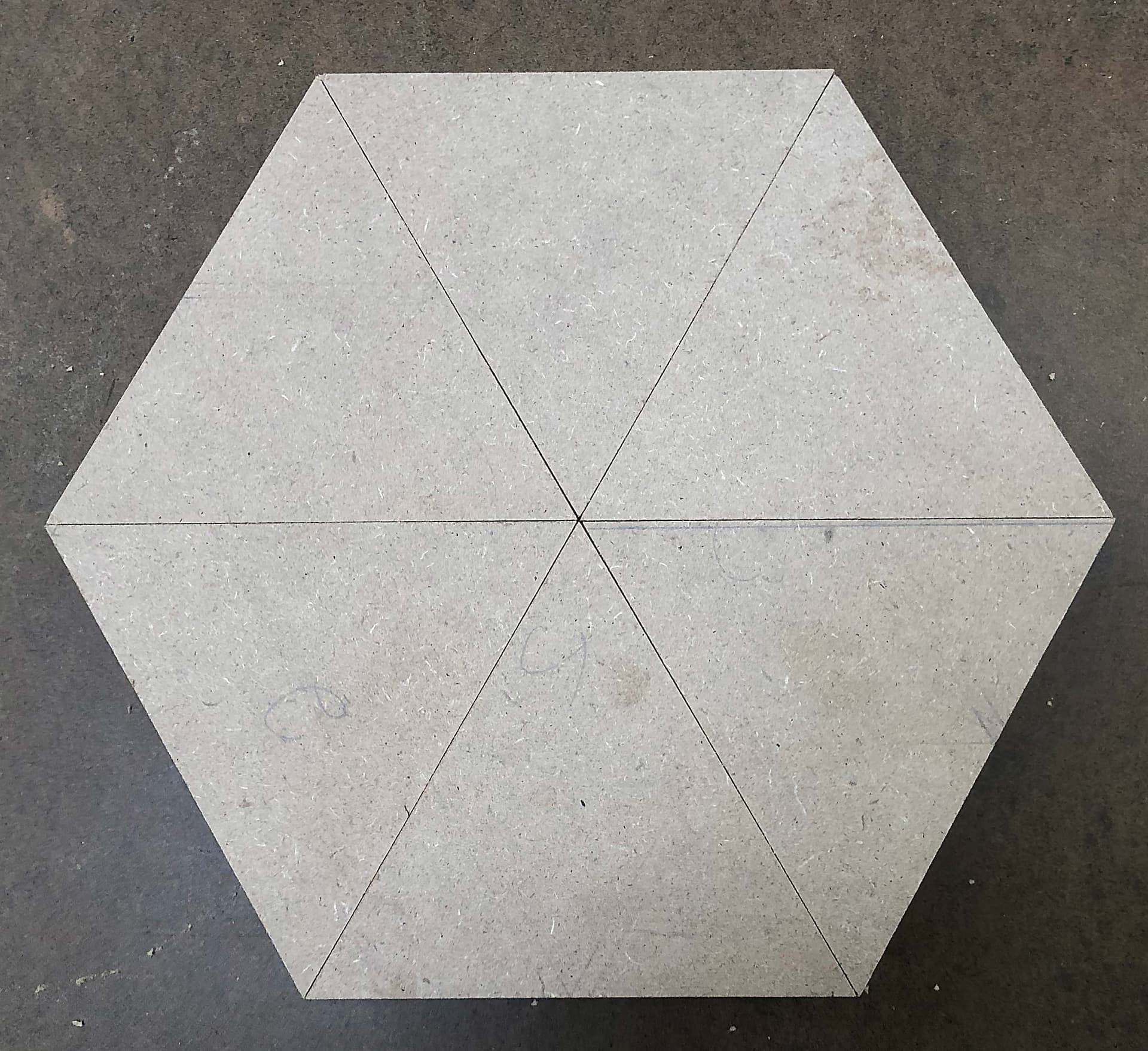
Cut 6 identical equilateral triangles to make the hexagonal base:
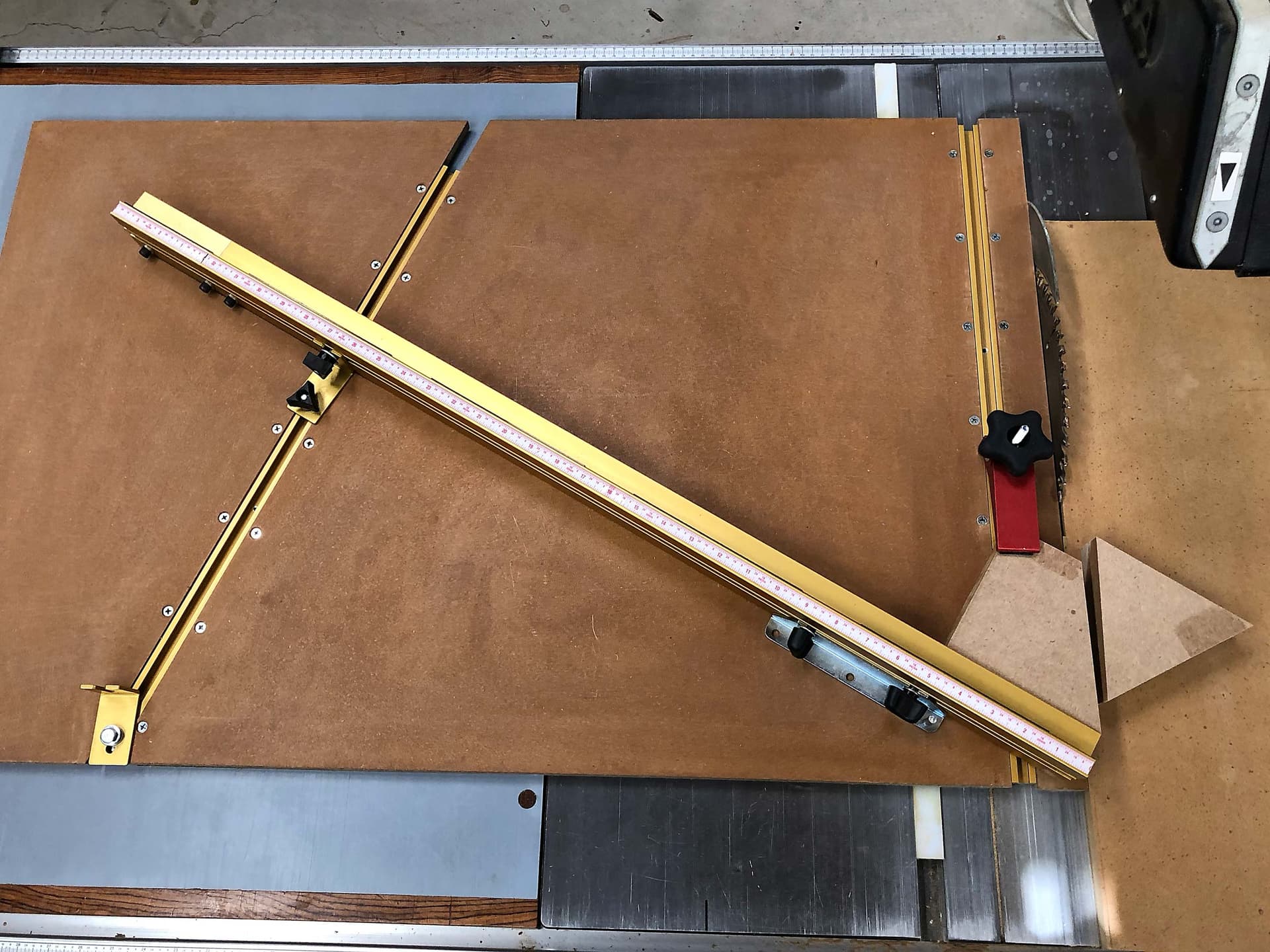
I have a largish tablesaw sled that I built a while back, with pivoting fence that attaches at the far end. This lets me make small adjustments at the far end to fine-tune the angle.
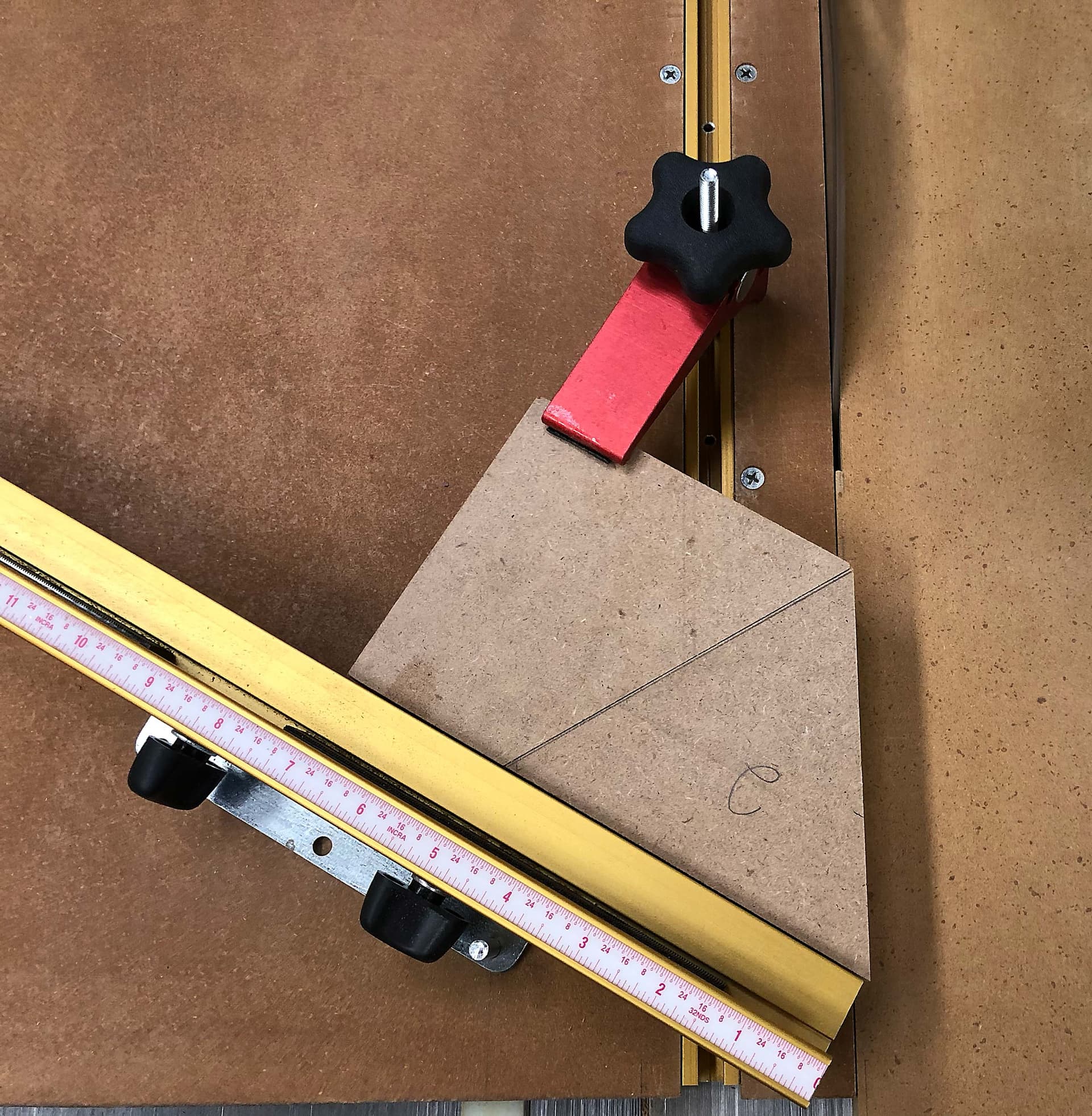
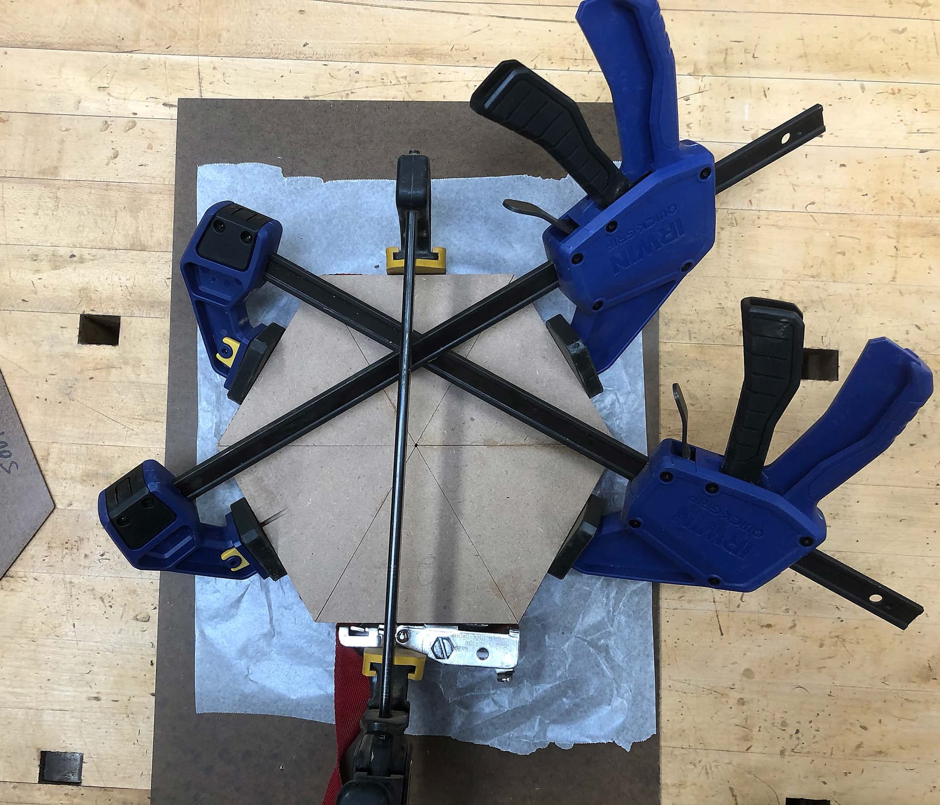
I had cut the triangles out of a single length of MDF (glued together to get the thickness I needed), but now I needed to cut them accurately to size. I used the remaining piece, turned around and clamped as the stop. I put each triangle into place and trimmed to size:
This was good in that I could adjust the tension on any of the 3 clamps to force the pieces into alignment.
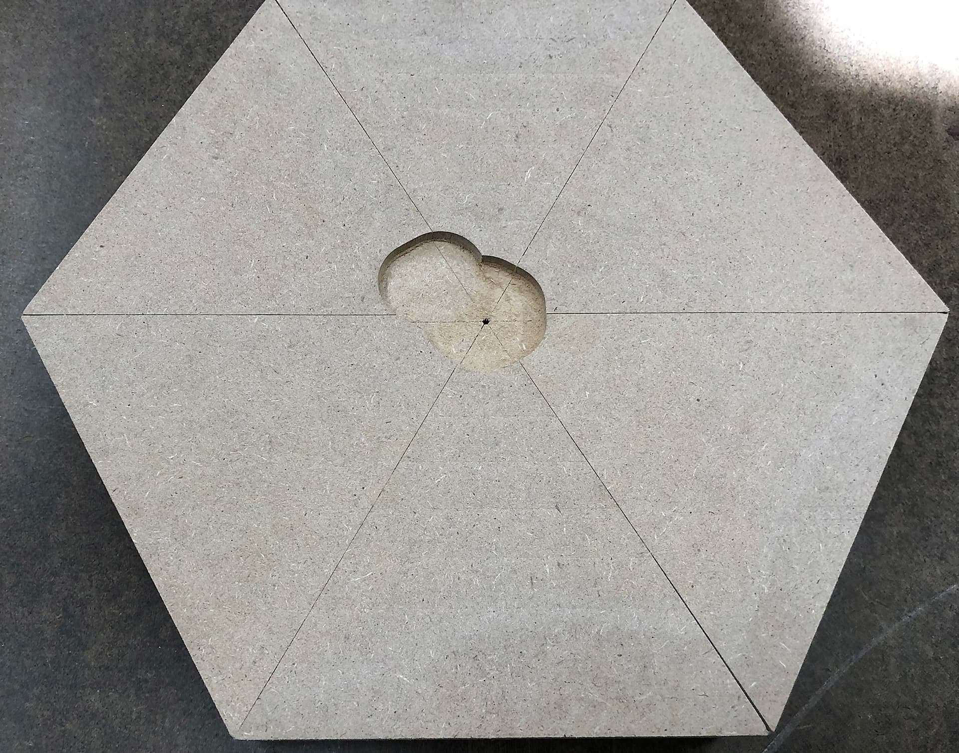
The next day I decided to surface the bottom since I hadn’t aligned the pieces that way all that well. Well, somehow I screwed up either in Carbide Create or in setting zero:
You can also see my angular errors here. Glue fills that with strength, and there will be a bottom plate glued on anyway. And, my design has those wedges and center hexagon covering all those glue lines anyway. BTW, the tiny center hole there was done on purpose with a hit of sandpaper on those corners before assembly.
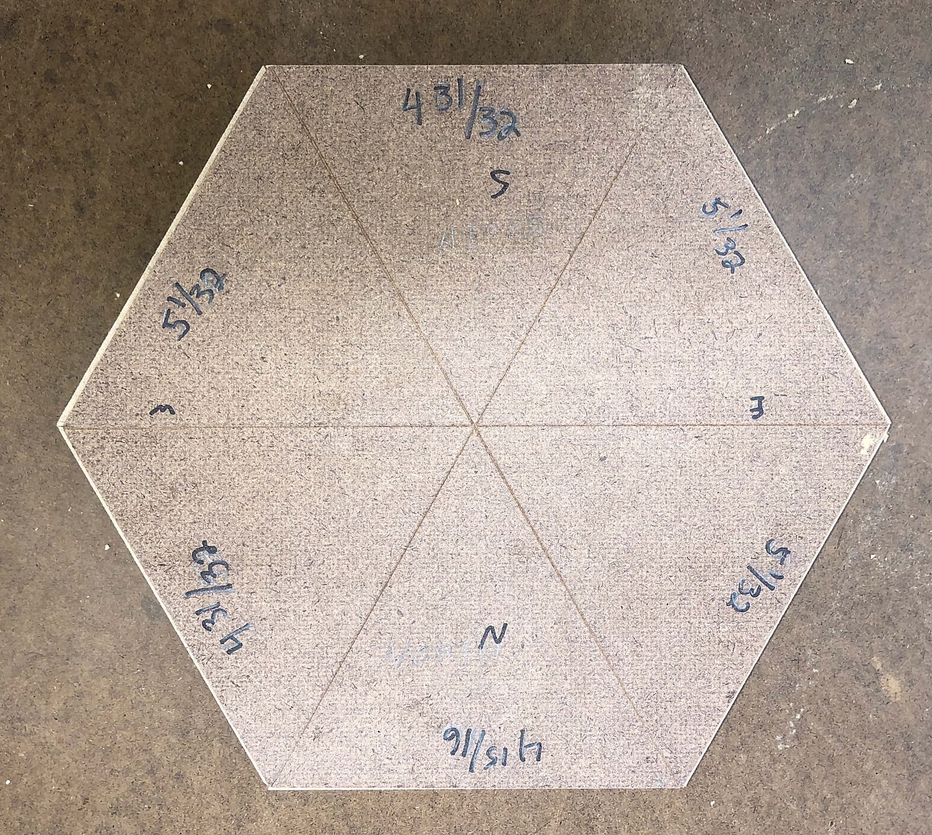
Since we had so much discussion on my existing posts being imperfect, here’s a piece of hardboard that I double stick taped to the top of one of the posts and then flush trimmed with a hand held router and measured. It’s on top of the MDF assembly.
You can see the MDF is larger than the post. I did measure and label each post’s side’s dimension (by eye). I’m going to leave the topper this much larger than the post and will have a ⅛" bottom plate that’s recessed ⅜" or so to create a ⅛" shadow gap between post and newel topper. This will help hide the differences (you’ll feel an overhang with your fingers all the way around), and besides my intent is that the newel topper is so pretty that’s what you look at.
I did get the assembly flattened, so the next step is to cut the big bevel. I’m going to do that on the tablesaw and hopefully will be able to leave just enough that after the wedges are glued in I can sand things smooth and to final size. Note that I’ll be doing 6 bevel cuts and if they don’t line up properly, you’ll see it in that the crease won’t go down the middle of the wedge (which aligns with the current triangle gaps). Make sense?
I am rethinking this approach, and wondering if I should just use the tablesaw bevel cut as a stock sizing/roughing technique and actually surface the bevel with a rounded bit in the Shapeoko before cutting the wedges. Thoughts?
I’ve now come full circle, and not just talking circle-inscribed hexagons.
Since I’m going down this path of leveraging the accuracy/repeatability of CNC, and no longer trying to make something that matches my irregular posts, here’s my yet-again-new plan:
Cut and glue up the main hexagonal pyramid larger than I need it to be.
Cut the wedges and center hexagon on the Shapeoko while that’s drying
Tablesaw rough cut the main hexagon pyramid leaving about 1/16" to 1/8" extra all around (in diameter and in cutting the main bevels).
Tape/Glue the pyramid to a rectangular piece of 19mm MDF. This will prevent future wedge pocket cuts from going into the spoilboard AND provide me with a persistent zero point. Easy to clamp onto the splilboard, too.
Rough-cut (Leaving under 1mm of material) the main bevels and outside edges of the pyramid with the Shapeoko.
Cut the wedge pockets and center hexagon pocket.
Glue in every other wedge, let dry (may use cyanoacrylate glue here to speed things up)
Re-cut the center hexagon pocket.
Glue in the remaining wedges, let dry.
Re-cut the center hexagon pocket
Final cut the outside edges and main bevels. This trims the wedges and the less than 1mm of material left by Step 4. Doing this together ensures they are flush. This “final cut” needs to leave something for me to sand smooth, don’t know if that’s 0.5mm or what yet.
Remove pyramid from rectangular base. Sand it.
Sand center hexagon, test fit, then glue in.
Cut a ⅛" thick piece of hardboard that’s about ⅜" smaller than the bottom of the pyramid on all edges. This will provide the shadow gap.
Screw and glue some blocks to the bottom of that for inserting into the hollow posts.
Screw and glue the hardboard to the bottom of the pyramid.
Take pictures, post a brag-and gag here, then do the other one, then do two others that are somewhat smaller, and then do two more than are even smaller.
Have a beer, then start an easier project, like making elephant head rattles.
@LiamN, I started to modify the file:
A) First I wanted to enlarge the main hexagon from 127mm to 128.2mm. This will provide me with the desired overhang to disguise the imperfect post match. I think I got that right.
B) Then I went to add the rectangular MDF base/reference. I created that as a new component (Side Note: it took me 2 hours in Fusion to figure out how to get the alignment of the rectangular base to the hexagon right. I finally figured out to first align a corner of the rect to a point on the hexagon, then align a side face of the rectangle to the side face of the hexagon, then move the rectangle 25mm away from the hexagon point so my BitZero fits.)
C) But now I need to move everything vertically 19mm so the bottom of the MDF is at z-axis zero. EDIT: Or, do I? Since I set origin in the Manufacture tab, the design origin shouldn’t matter anymore, right?
D) I’m not sure how to best setup origin/zero for the center hexagon. I can screw a board to the bottom, clamp the board, and then mill tops and sides, but it might get tricky to precisely find the center of my stock, which will be rectangular. So I might want to do repeat the zero point thing again that I’m doing for the main pyramid. Thoughts?
Nice tablesaw jig, I might have to make one of those myself.
Like many woodworkers, I’ve made my share of jigs. This one is made from Incra T-tracks. I’m not happy with how the pivot ended up working - I should have gone with a standard miter gauge and just ignored the markings on it. But having the wide support locking and ability to leave a 90 degree locking piece in place has been great. I also have a separate off-shoot support sled on the right there.
Right, I may have more questions than answers for you at this stage…
I think many of us recognise that feeling
Great, figuring out where your persistent zero is really helps think through the rest of your machining. You’ve spotted that I had several versions of X, Y, Z zero in the CAM.
Question here, do you plan to have a flat hexagon and use the Shapeoko to rough out the pyramid shape of the overall element? If so we need some toolpaths for the main faces and we need to tell Fusion that the stock is flat and not pyramid shaped or it will get a bit optimistic about cutting depth at the edges.
Yep, makes sense to re-run that contour each time, so long as you don’t move or lose zero. As you’ve got a persistent place to put your bitzero, so long as you can get the board straight with X and Y you can even remove it from the machine, put it back and re-zero.
Yep, as for how much, try it and see, if you use a ballnose then 0.5mm or less is likely OK.
So, an adapter plate then?
Of course in a few weeks you’ll want to machine a pyramid ‘soft jaw’ to flip the newel top into and directly machine the post adapter in the bottom of the pyramid
Sit and look at what you made, criticise all the things you think were mistakes or you could have done better, try to resist the urge to make it again…
Yep, looks like it, that’s in the main sketch “127mm hex” ?
Ah, I’m not sure this is how you want to do that…
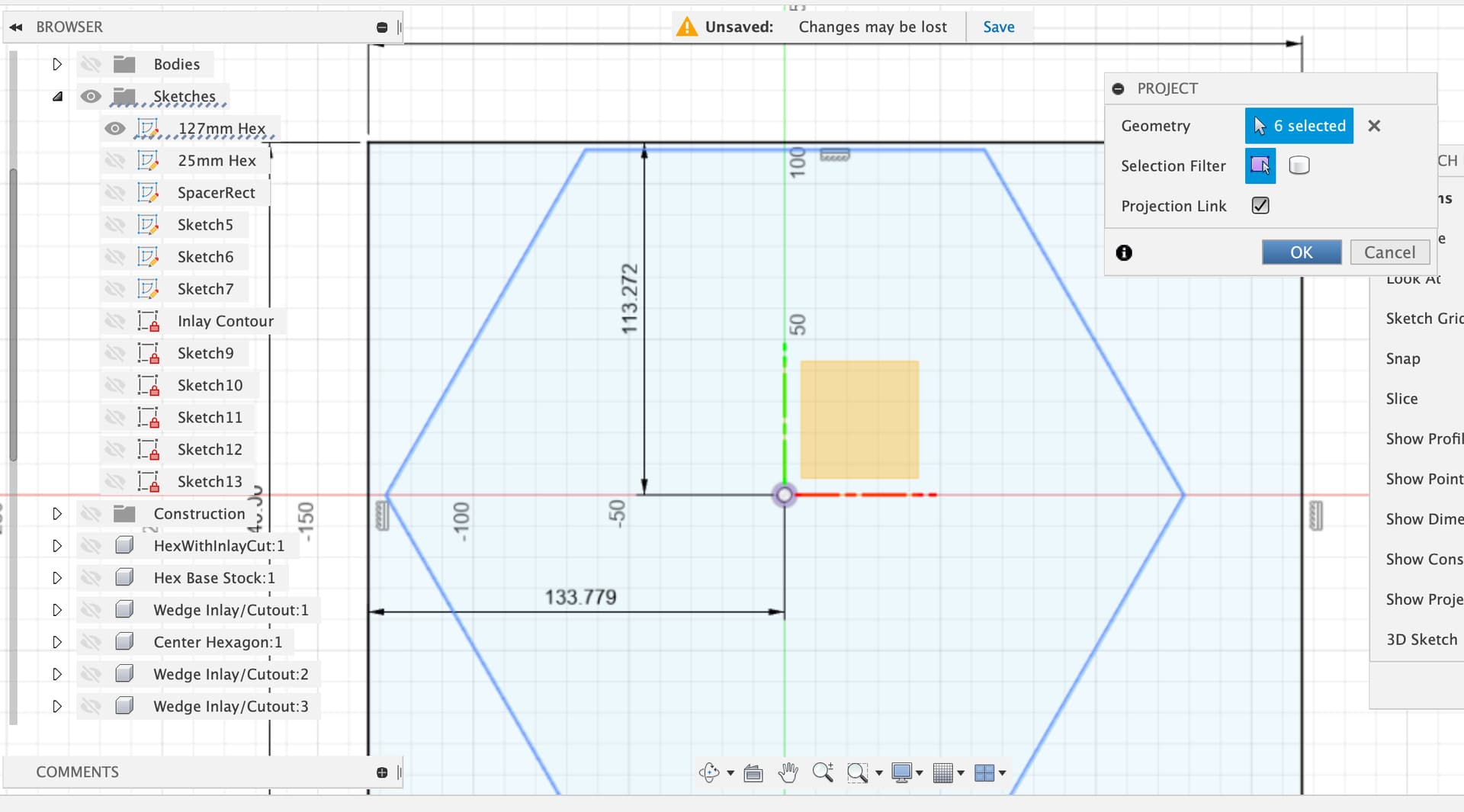
If I have worked it out correctly you made a new component “RectangularIndexableBase” - good, you sketched and dimensioned the base and then extruded it. Then I think you manually aligned that base with the hexagon and moved the component into place.
There’s a couple of problems with this, the first is that there’s nothing holding that component in it’s new position and the second is that there’s no cleanly defined relationship between the hex edges or center and the rectangular base. The warning is the two different origins which you can drag around by dragging the components.
There’s several ways to do this a bit more cleanly, one option is that in the sketch for the base of the rectangular base you could turn on visibility of the main hex, and then project the sketch “127mm Hex” into this sketch to give you the outer permiter of whatever your current hex is. This means it’s connected and will update if you change the dimensions in the main hex.
Once projected we can start to tell Fusion about how we want the relationships to work.
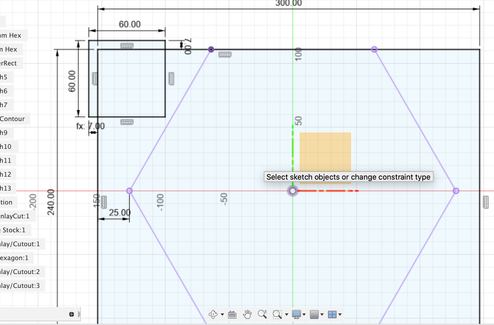
What I’ve done here is kept your square plate dimensions but I have told Fusion that the top edge is coincident with the top edge (Constraints - Coincident). That lines up the edge as I think you intended. Then I put a 25mm dimension from the corner of the main hex to the edge of the rectangle, again I think that’s how you lined them up. Finally I drew in the 60x60 Bitzero so we can visually check whether we have left space for it.
I told Fusion to reset the manual positioning to let dimensions define things instead.
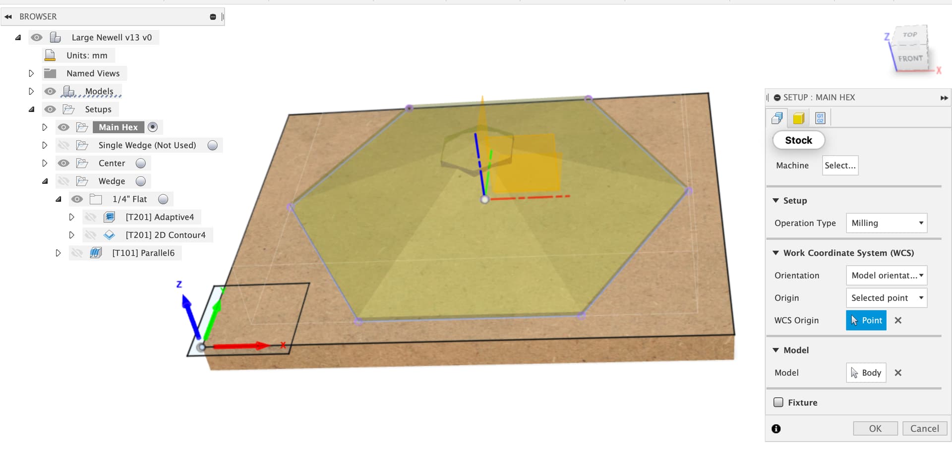
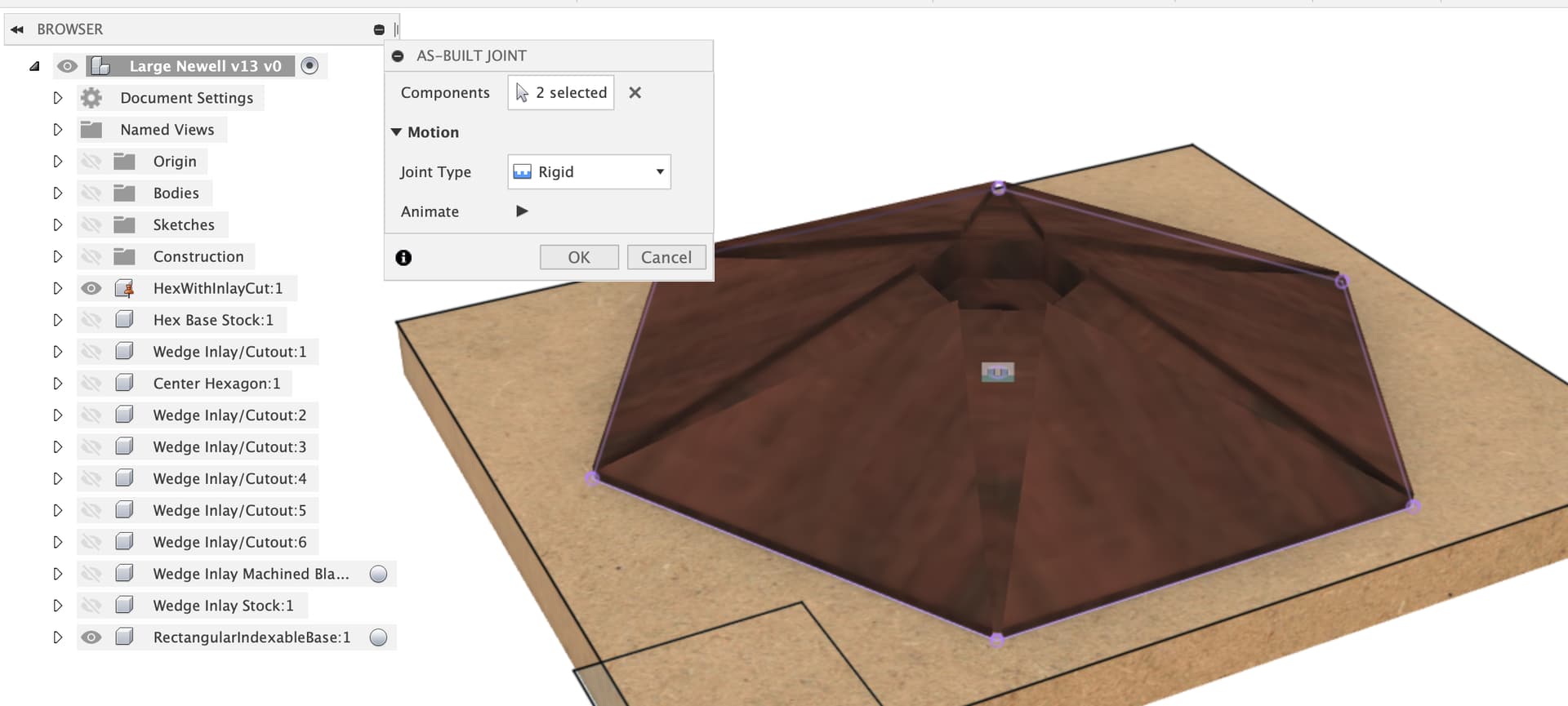
What I would do now is “ground” the main hex and then add an “as built joint” between it and the rectangular base to make sure they stay aligned as drawn (separate components can be moved relative to each other as you’ve found out)
I would suggest using the top of your MDF board as Z zero. You can just select the bottom corner of the MDF as zero point instead though if you prefer.
Ah, saw your edit - correct, Z plane and zero are configured in each CAM setup so you can represent which way you’re putting the workpiece on the machine, not how you drew it.
So, we’re talking about machining the center hexagon out of a chunk of rectangular stock?
If the stock is slightly oversized then we’re not too worried about exact center, just ensuring that the final solid is within the stock. This also means it doesn’t need to be exactly square either.
I suggest drawing the stock as a component and then creating a CAM setup using that stock, then we can see what might work?
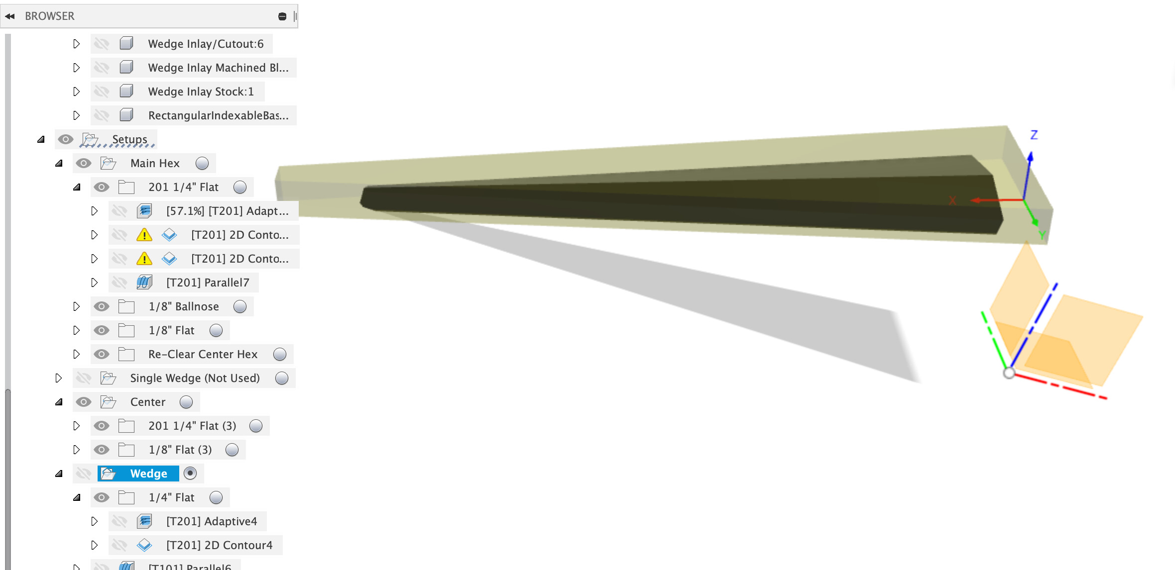
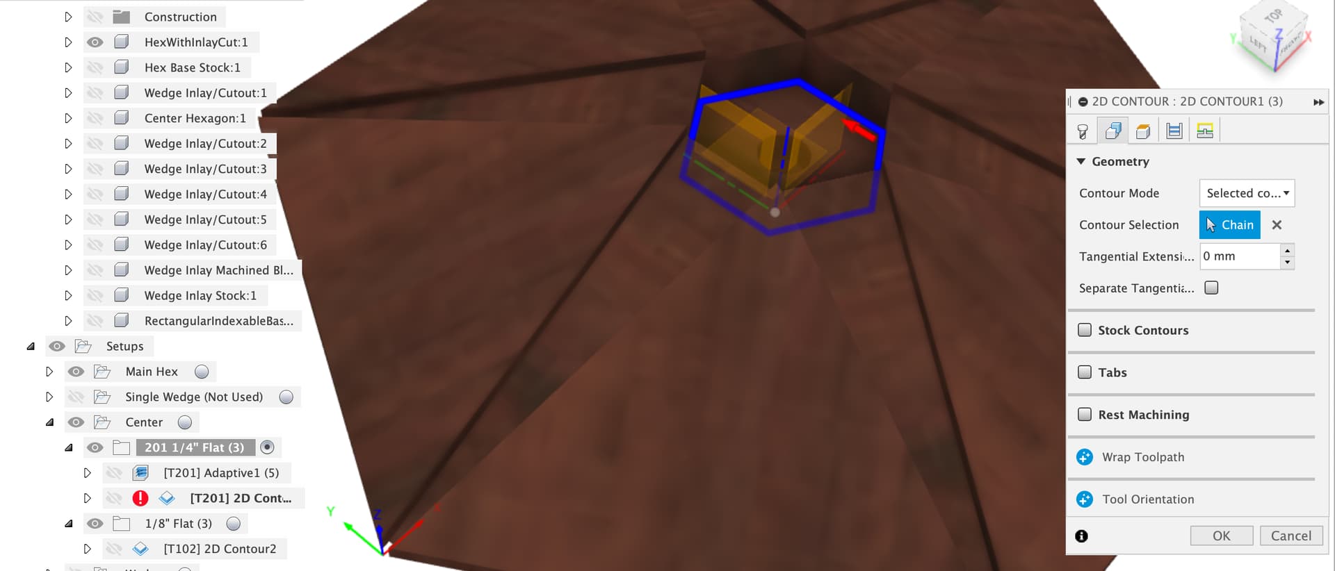
One key thing to spot here is that the Z plane is set to be ‘flat’ with the bottom of the wedge insert for machining, not sure if that was clear or not. Obviously you can put the zero point wherever you think it’s convenient for setting up the workpieces for cutting. As you’re making several you might want to make a jig to hold the raw stock, maybe mill an indent into a piece of MDF?
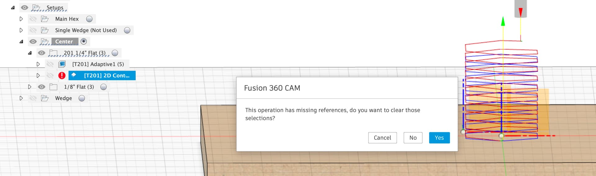
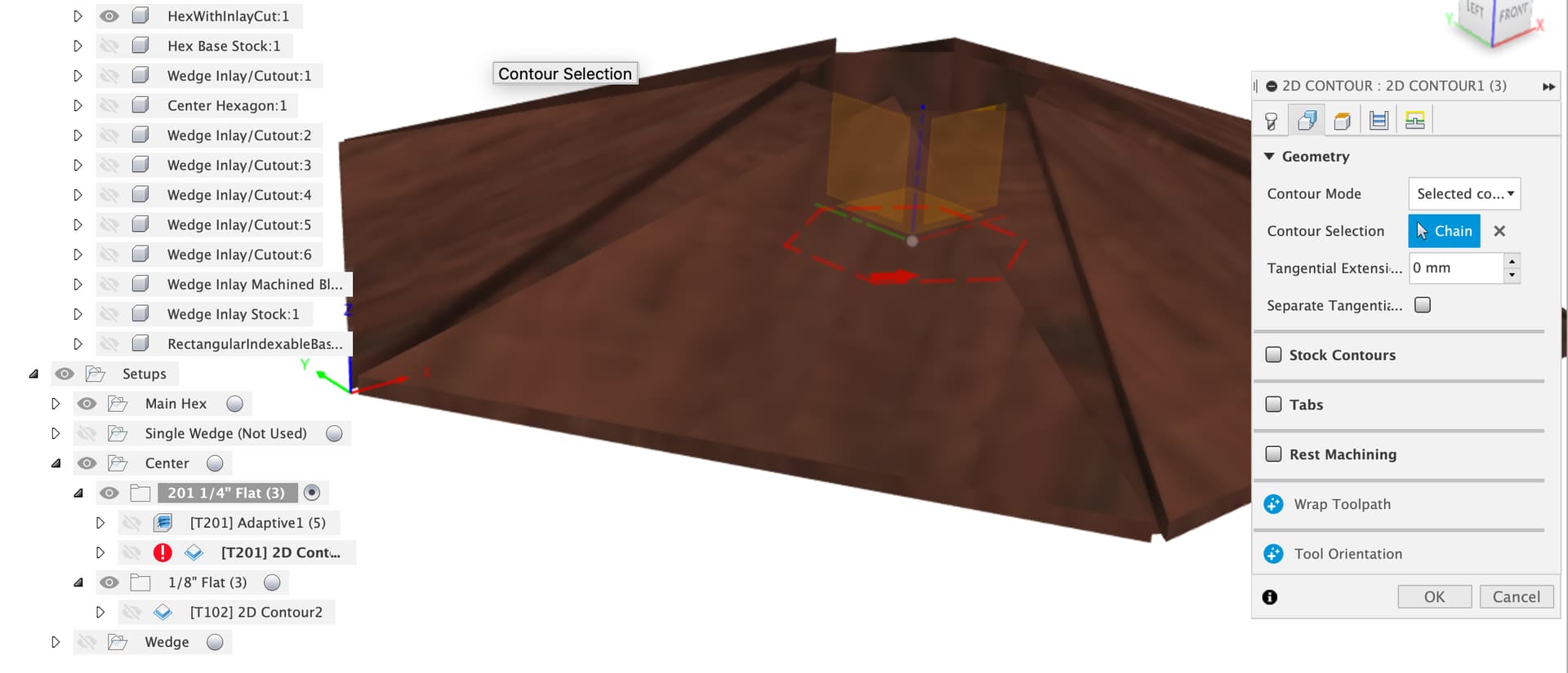
Ah, my fault, sorry, if you edit that toolpath and say no to clearing the selections you’ll see I’d selected the bottom of the central hex cut out before filling that in.
Question here, do you plan to have a flat hexagon and use the Shapeoko to rough out the pyramid shape of the overall element?
I keep going back and forth. My natural instinct is to rough cut the pyramid on the tablesaw, leaving like 1/8" to 3/16" of stock to be removed by the Shapeoko, as that saves time and wear on the workhorse ¼" bit (but I’ve got 3 of them now). But, maybe I should embrace the CNC way and do the whole thing on the Shapeoko. So, let’s do that for now.
If I have worked it out correctly you made a new component “RectangularIndexableBase” - good, you sketched and dimensioned the base and then extruded it. Then I think you manually aligned that base with the hexagon and moved the component into place.
Yup.
There’s a couple of problems with this, the first is that there’s nothing holding that component in it’s new position and the second is that there’s no cleanly defined relationship between the hex edges or center and the rectangular base. The warning is the two different origins which you can drag around by dragging the components.
That’s exactly right - it needs to be parametrically aligned/set. I still struggle with getting Fusion to do even basic things for me as its way of working is completely different than what I’m used to (such as Adobe Creative Suite, especially Illustrator & Photoshop). I keep hitting the space bar to get the hand tool, for instance. I clearly need to learn how to tell Fusion about relationships and such. For instance, even the spacer cube thing I created for the wedge sides is just out there. When I resized the pyramid from 127 to 128.5mm, that spacer cube should have moved 0.75mm out as well, but not doing that changed the wedge dimensions just slightly. It’s fine, but I’ll have issues when I do the other size (much smaller) pyramids.
So, we’re talking about machining the center hexagon out of a chunk of rectangular stock?
Yes.
If the stock is slightly oversized then we’re not too worried about exact center, just ensuring that the final solid is within the stock. This also means it doesn’t need to be exactly square either. I suggest drawing the stock as a component and then creating a CAM setup using that stock, then we can see what might work?
OK, so I should expect to have the origin for CAM at the top center of the stock, assume my stock is generously oversized, and mill from there. That’ll save me some milling on the tablesaw (you see, my tune is changing from doing things manually first and only using the Shapeoko for accuracy to just doing the whole thing on the Shapeoko).
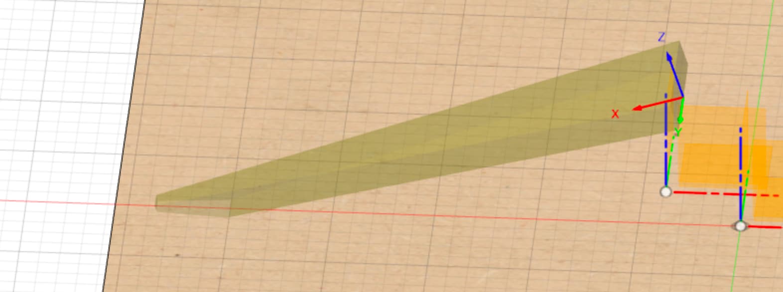
One key thing to spot here is that the Z plane is set to be ‘flat’ with the bottom of the wedge insert for machining, not sure if that was clear or not.
Yes, that’s what I was expecting. I think that means the back face of the wedge, where it’s thickest, cannot be cut on the Shapeoko since top of it tilts away from the bottom (it’s vertical when installed, but that’s because the bottom is angled). That’s OK since the wedge is longer than it needs to be and will be trimmed after gluing in place. Will Fusion give me a warning about not being able to mill that face?
As you’re making several you might want to make a jig to hold the raw stock, maybe mill an indent into a piece of MDF?
I don’t think that’s going to be possible, as cutting the sides of the wedge accurately is just what the CNC is ideal for. Now the question becomes do I rough cut each wedge as a blank out on the bandsaw or do I just use the bandsaw to slice to approximate thickness and then cut multiple out on the Shapeoko using tabs? I think not having tabs on those critical sides is best. I can have a stop to register that unmillable back face against, and that works well for the zero point you’ve setup. I guess it’s just tape and cyno glue for stock holding.
So, when you say “do something about the center hexagon”, what needs doing here?
It’s what we discussed earlier, about screwing/glueing the raw stock to some kind of base plate and zeroing manually at the top center of the stock. The Shapeoko can cut both the 6 sides and the top bevels. I need to decide if the sides should be sharp edges on the CNC and round them over by hand, or design in a 1/16" radius rounding to match the pocket made by the ⅛" bit. The later is more elegant, right?
You’re right about the table saw being faster and the CNC being good at accurate finishing, but this isn’t a particularly large part so it won’t take too long.
You’ll need to adjust the stock model to represent the new stock shape and a toolpath to cut the whole surface down.
Yep, it’s a steep learning curve, Lars Christensen’s videos are great for getting the basics
I had a quick look and I think I’d put the hexagons and rectangle from 127mm Hex, 25mm Hex and SpacerRect sketches all in one sketch so that I could use dimensions to hold them in position.
I’ve been watch Lars, but honestly I think he needs a PIP window to show what he’s doing with the mouse and/or keyboard. I know how to dimension rectangles and such, but I never get it the correct field to highlight just at the right time.
You’ll need to adjust the stock model to represent the new stock shape and a toolpath to cut the whole surface down.
OK, challenge accepted - going to try that now.
I had a quick look and I think I’d put the hexagons and rectangle from 127mm Hex, 25mm Hex and SpacerRect sketches all in one sketch so that I could use dimensions to hold them in position.
Well, I certainly don’t know how to combine sketches, especially given doing that inside of an existing history timeline without messing things up later. I guess I’ll worry about those after getting these pyramids built.
Your use of the construction planes to slice things up is pretty strong CAD Fu so once you figure out where the buttons are in Fusion I suspect you’ll do rather well
Am I right in thinking the spacer rectangle is there to set the corners of the cutting planes for the wedge?
Yeah, I wanted the wedge to be between 2mm and 3mm in thickness at the edge of the pyramid on the vertical face (which itself is only 3.175mm tall). I did the spacer rectangles before I understood converting sketches to construction, but even that wouldn’t parametrically tie them to the pyramid size. The point of the pyramid should be on the plane of the near face of the spacer rectangle (which doesn’t have to be a rectangle at all, it’s just spacing so should be a line 2mm long).
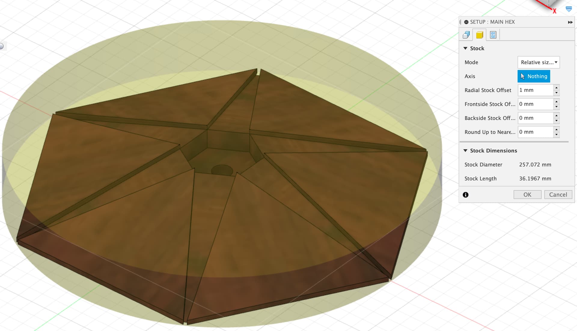
So, I’m looking at how to model the pyramid stock in the Manufacture tab. A rectangular box is too big, so the Relative Size Cylinder seems the best bet:
I think there’s a simpler way, in the 127mm Hex sketch make a hexagon the size of the stock you think you’ll have after glue up, centered on the same origin, then just extrude that upward to the thickness as a new body.
Won’t changing the size of that hexagon affect the size of the finished pyramid? Or are you talking about adding a new hexagon to that sketch and extruding that - and if so, why start in the 127mm Hex sketch?
I just tried a 40mm thick blank and got over an hour for the adaptive clear toolpath which seems like an argument for roughing the blank on the table saw…
I’ll have a go at a slightly oversized stock piece for the main hexagon.
In the meantime, WRT using the same sketch for multiple things, I had a go to see how I might model the project using fewer sketches and some parameters to make it easier to change dimensions and keep things referenced to each other. The outcome of that is attached. Not suggesting you should change from your current model, just an example of how it might be done.
If you back up the history bar at the bottom to zero and then step forward one by one it will show you the steps to build that up.
The reason specifically for putting the stock hex in the same diagram as the body it is the stock for is to make it easy to control the relative position of the two bodies and keep the stock enclosing the final body.
OK, I like the “another way” - much more straightforward. For instance, using Loft instead of Taper Angle on the Extrude is much more logical. Still need to run the Manufacture passes on it.
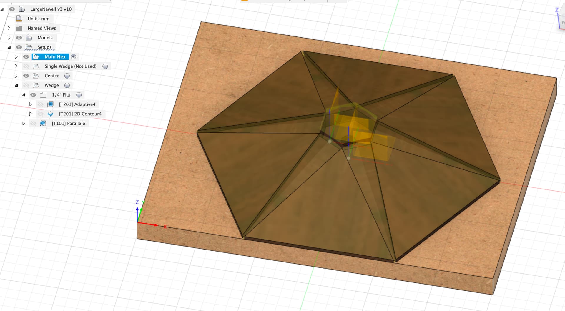
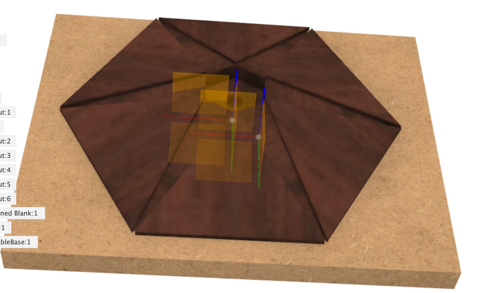
There is one issue I think both ways have. See picture:
I understand the triangular gap with the curved “bottom.” My order of construction would have that partially filled in with the extension of the first glued-in wedge:
And then for the second wedge I’d have to do some hand trimming on that back plane to get it to not interfere with the first wedge but still fill in the remaining gap. Hmm. The only other option is use a chisel on the inside hexagon pocket corners. Thinking about it, that’s probably a better look.
Or, am I suffering from too much enlargement and could probably just compress the fibers to fit?
But, my real question is on the amber thick arc. What is that the result of?
And on what stock to start with. An hour on the Shapeoko isn’t so bad since it’ll save me setup time on the tablesaw to cut the angle with enough clearance and avoid the risk of screwing up on a pass (need six per pyramid). And like I said, the time-lapse of starting with a thick block will look cool.
I’ve already spent so many hours on this that having an extra hour cutting time when I’m not making that many seems easier, actually.
One thing I should have mentioned about the sketches in this alternate version, after the first “Base Plan” sketch all the others use either the same origin and dimensions or projections from other sketches to keep their geometry aligned. Any time you can’t just put the geometry in one sketch to keep it aligned a projection from another sketch or a solid body is a good second choice.
Ooops, my bad, forgot to check that after putting the fillet radius in. On the upside the fillet radius is representing the contour the machine will actually be able to cut so it wouldn’t be able to get that sharp corner anyway. You’d definitely end up doing a little hand fitting with a chisel on the wedges during installation though.
The gap the machine can’t get into is fortunately nice and small
Sorry, that was my automatic mode drawing things for CAM, I added a parameter “Center_Post_Insert_Clearance” which does an offset face to give clearance all round the outside of the center post insert, this would be adjusted as you do the CAM tests to give you just enough wiggle room to insert the center post in the slot with some glue. It’s set at an initial 0.1mm right now, I’d start at zero and slowly walk it up until things fit.
OK, I’ll pull the CAM over to this version tomorrow if you’d like to run from here, adding in the stock won’t take long.
I have the side angles almost the same as in your model, wasn’t sure if angles or height were your critical dimension, I don’t think I have the center post the same height as yours but those things are all in Modify / Change Parameters to change and see the result easily.
So far the most changes I’d make are pretty straightforward:
Outer Hex to 128.5mm from 127
Wedge Tip Width to 2.5mm from 3
Flat Base Thickness to 3.175mm from 3
Center Plug Depth to 12mm from 20mm
Center Post Height to 10mm from 15mm
I didn’t see a reason to have the center post much longer than it needed to be. Cutting that pocket just a few mm deeper than you can see is all one needs, right? And I don’t need the hole in the center since I’ll be attaching the flat hex stock to a 19mm MDF rectangular base for clamping and BitZero-ing purposes. I’ll probably C-clamp the two together (another reason to not cut the bevel ahead of time), drill a hole through the MDF up into the pyramid and use a screw. Then take apart, do the tape/cyno glue thing with the screw (maybe not use accelerator to give me a few seconds to be sure my alignment is right).
I couldn’t figure out what Hex Face Angle does? That would seem to be a derived value, no?
And Wedge Root Depth? Is that how thick the raw stock for wedge should be?
I don’t have experience to know what kind of surface to expect from the ball-nosed bits. I probably won’t plane the surface as these exotic woods can tear-out. I’ll either use a disk sander or just do it by hand. So the trick will be to leave enough material to sand to get a really smooth finish without leaving too much to make sanding laborious and possibly error-prone (too much sanding on one face will mess up alignment with the two adjacent faces).
I figured that arc was component clearance after sending the message. And the size of 0.1mm in that screen short shows just how deeply I had zoomed in. The 1/16" radius will be fine on that center hex pocket and piece.
For manufacturing, will still need to extend the back face and top faces 1 mm or so. We’ve already talked about running the center hex pocket finishing cuts multiple times (after each wedge glue-in round), but I think the main pyramid face finishing pass should be done only once, after all the wedges are glued in, right? Or, will I need to run some kind of intermediate roughing pass in case the wedges stick up too much for a finishing pass? I’m on a Shapeoko Pro Std, so things should be pretty rigid and my gut tells me that since I’m sanding anyway that the pyramid finishing pass with the ballnosed bit can be done just once after the wedges, which protrude slightly, are glued in.
And I guess the question you can’t answer is whether it’s worth while for me to go for the 1 month Fusion360 trial to get multiple tools used in a single file. I guess it’s not a huge deal since there are only 3 tools (¼ end mill, ⅛ end mill, and ballnose), right? Or, do you recommend using both ¼" and ⅛" ballnose passes?
I updated the parameters as you listed, you should be able to change those and have the shape update. No center hole this time and I copied over the rectangular MDF base with space for the bitzero. It’s worth a try with just a couple of screws I think for workholding, just make sure they’re short enough to not end up in a toolpath from the other side…
Hex face angle did nothing at all, I forgot to remove it after not using it. For parameters, try deleting them, if they’re in use Fusion gives you an error, if not you didn’t need them anwyay.
Wedge Tip Depth and Wedge Root Depth define the thickness of the wedge at both ends. I wasn’t sure exactly what decisions you’d made in projecting the wedge but it looked thicker at the root than the tip so I copied that.
The ball nose surface is a bit ripply and I think needs sanding, the bigger the ball nose or the smaller the stepover the better it gets but smaller stepover means longer jobs. I’ve set up a final ballnose toolpath to do the whole surface, the stepover can be adjusted to whatever you end up preferring.
Yep to most of that, I re-sequenced a load of the CAM to do the main hex with a roughing finish and then a finishing pass over the whole thing with wedges glued in. The wedges are slightly oversized for glue in to be levelled in the final toolpath. I think that’s what you meant?
I am quite happy to run each tool as it’s own job, frequently you want to adjust the parameters on a toolpath and re-run it anyway. The main issue to me is the loss of rapids in the free version.