Tool(path) time 
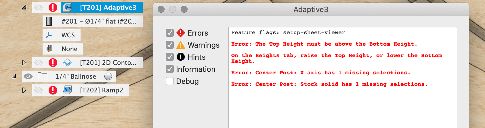
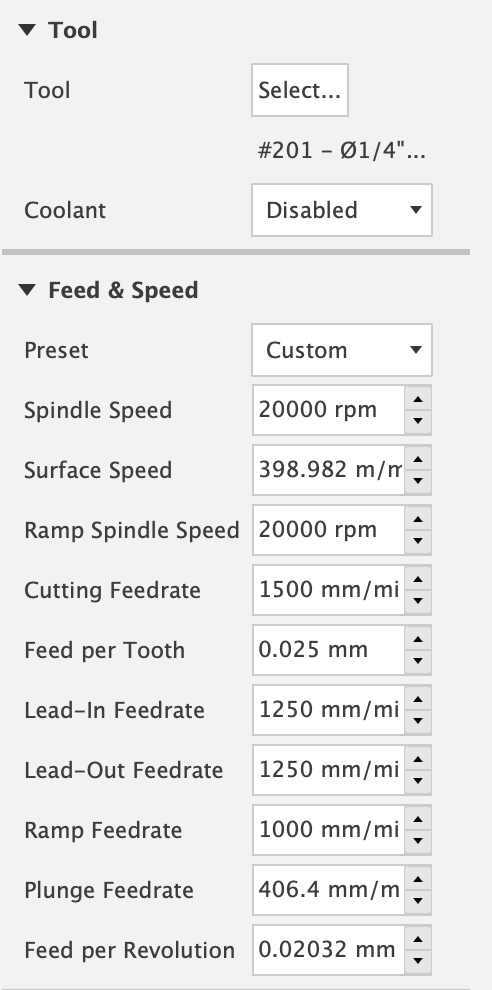
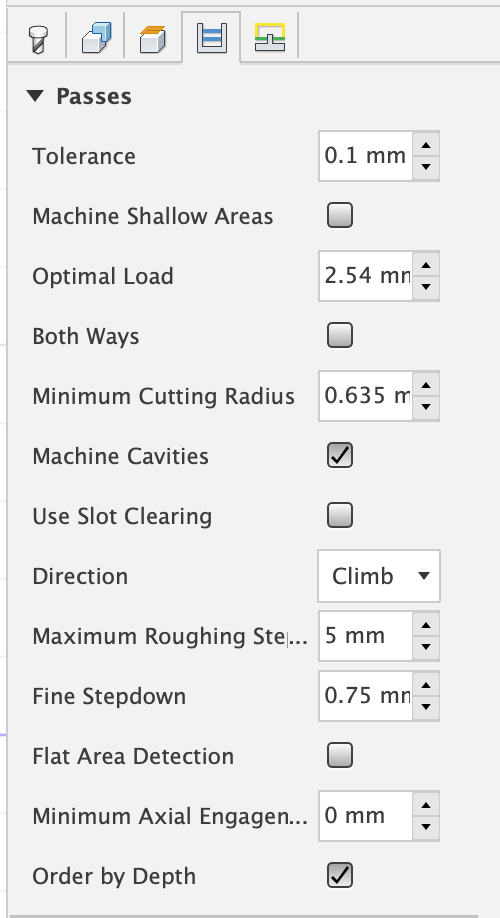
Repeat warning, these feeds, speeds etc. in the toolpaths are based on what I would run, whilst using my ears, feed rate override and small amount of common sense I posess to try not to break the machine, cutter or workpiece. Don’t assume any of them are ‘good’. We should also expect that I have made at least one stupid mistake here that I have not seen in toolpath simulation but would only see when running the job in the real world so start on some cheap stock. Run the Fusion simulation for all the toolpaths before you send them to the machine so you know what they’re meant to do before pressing START
I’m also sure there’s better ways to do this and will not be at all offended when somebody else points out better ways or problems with this one.
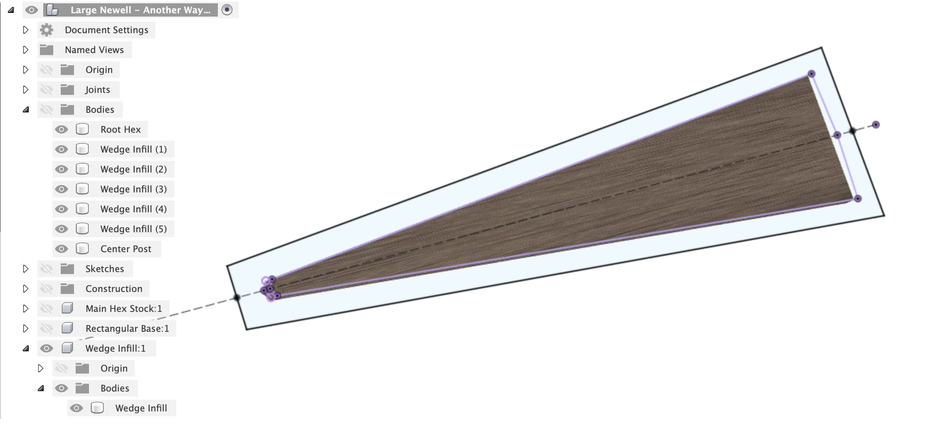
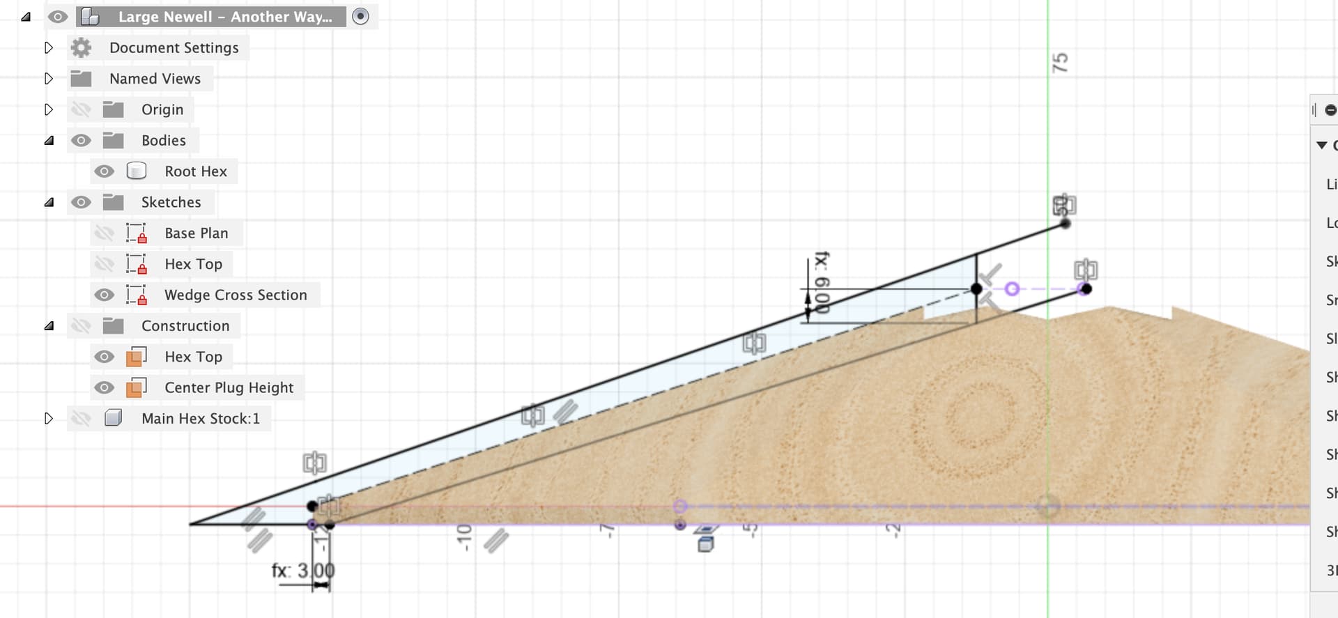
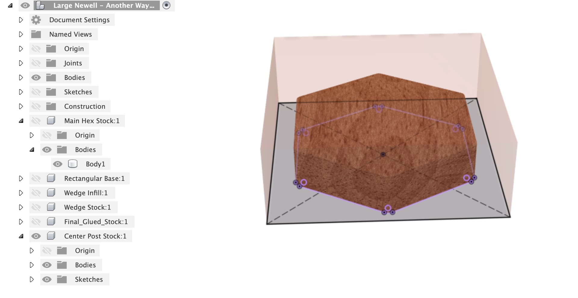
First up, I made a new component for the base hex stock, flat this time to let the CNC do the work, you’ll get to play with how deep and fast you can run an adaptive clear on the Pro 
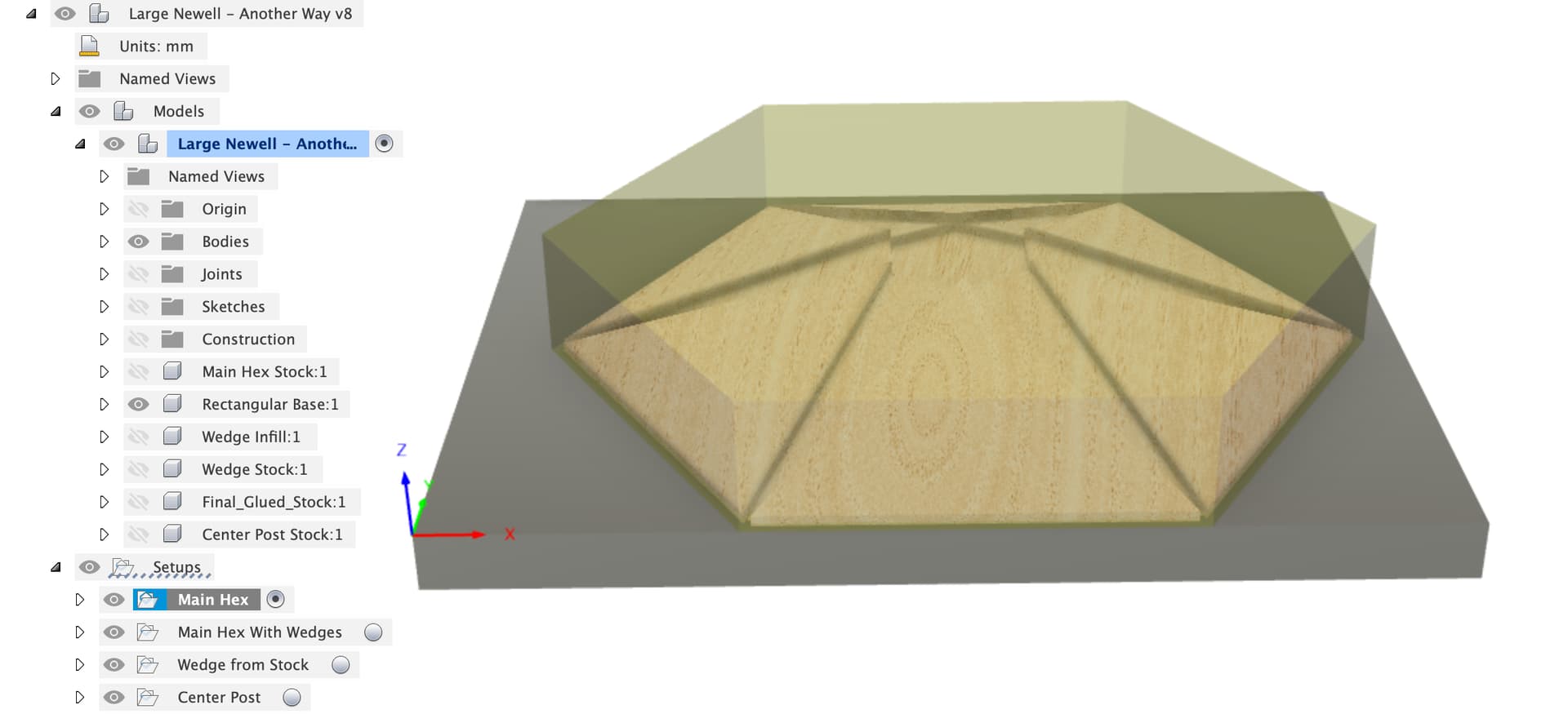
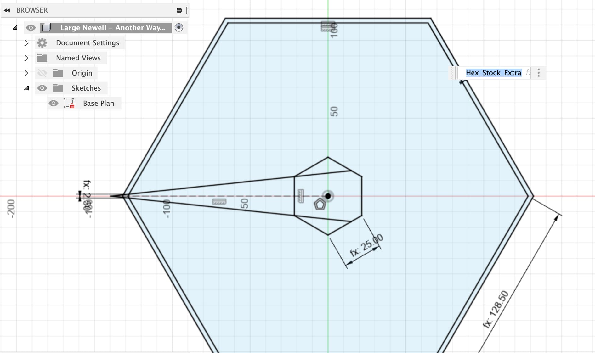
The stock is just an extrude up and down of base hex outline, offset by Hex_Stock_Extra parameter
It then extrudes down to the base with total height Hex_Stock_Height from the parameters.
The same MDF flat base is in there (depth doesn’t matter as we set Z zero on top of the MDF) with X, Y zero set in the bottom left corner where the bitzero likes to do things. I have attached the various other components to the main hex with an as-built joint to make sure things don’t move around.
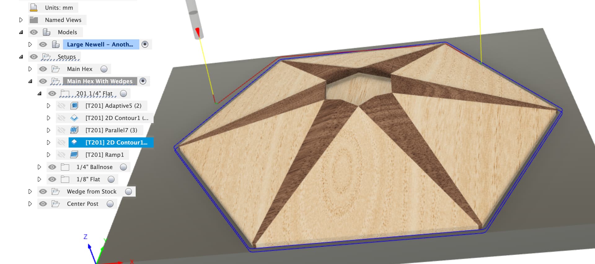
The first machining setup is “Main Hex”, this uses the MDF base, sets the Main Hex Stock component as the stock and the Main Hex as the body. If you leave the main hex on this board attached to the Shapeoko until the end the rest of the alignments should work OK. If you take it off you’ll have to be sure the rectangular board is square to the machine both times.
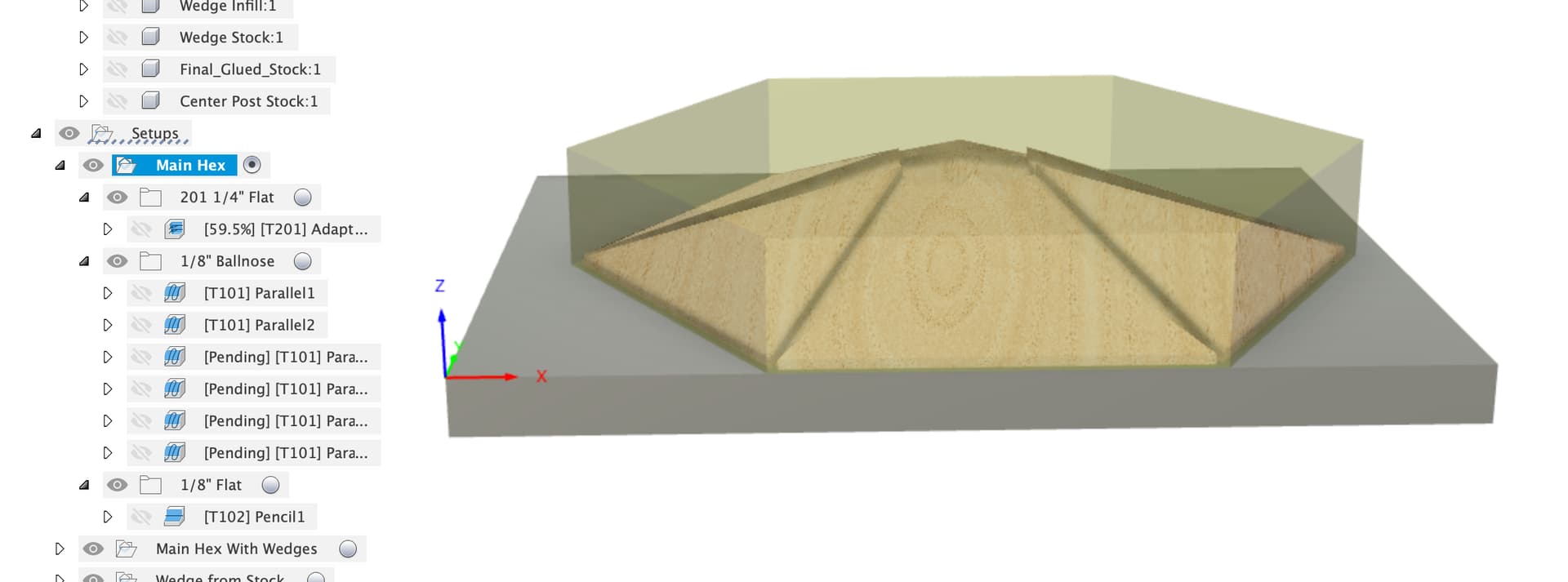
First job is a big adaptive clear. If your workpiece is well held down on the Pro you can probably push faster or go to a deeper DoC, your ears will tell you once you start, use the feed rate override to test going slower & faster. It’s a long job so it’s worth tweaking to see how fast you can go.

Next up it’s the 1/8" ballnose to clear out the slots for the wedges, this is done in two steps as the 1/4" didn’t clear to the end of the slots and the depth of engagement might be a bit much for the 1/8" bit. First pass is at 2mm stock to leave

Second pass is the whole length with no axial stock to leave, both have radial stock to leave to stay off the walls.
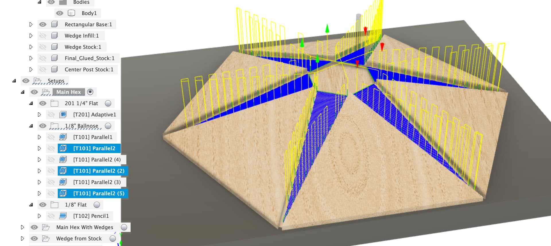
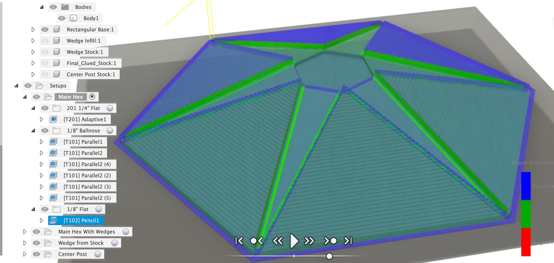
Last op in this sequence is a Pencil toolpath down the side walls of the wedge slots to get them straight and clean using the 1/8" flat ended cutter. This will not quite give a square corner due to the slope, shaving a bit off the bottom edges of the wedges should fix that and those are hidden anyway.

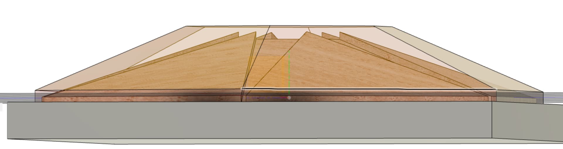
So now we’ve got the main hex roughed out and the wedge slots cut.
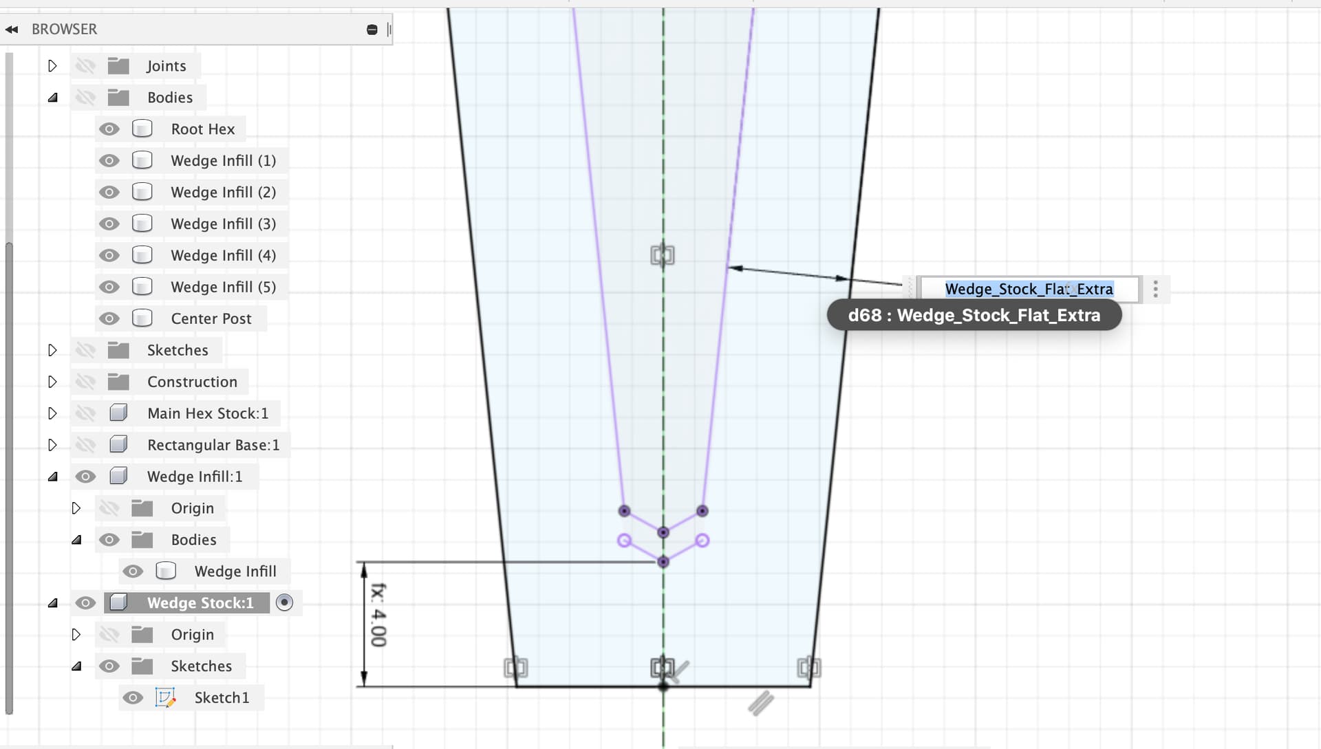
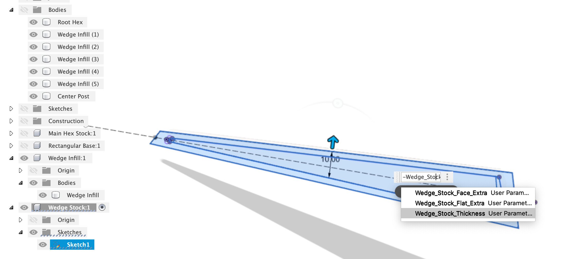
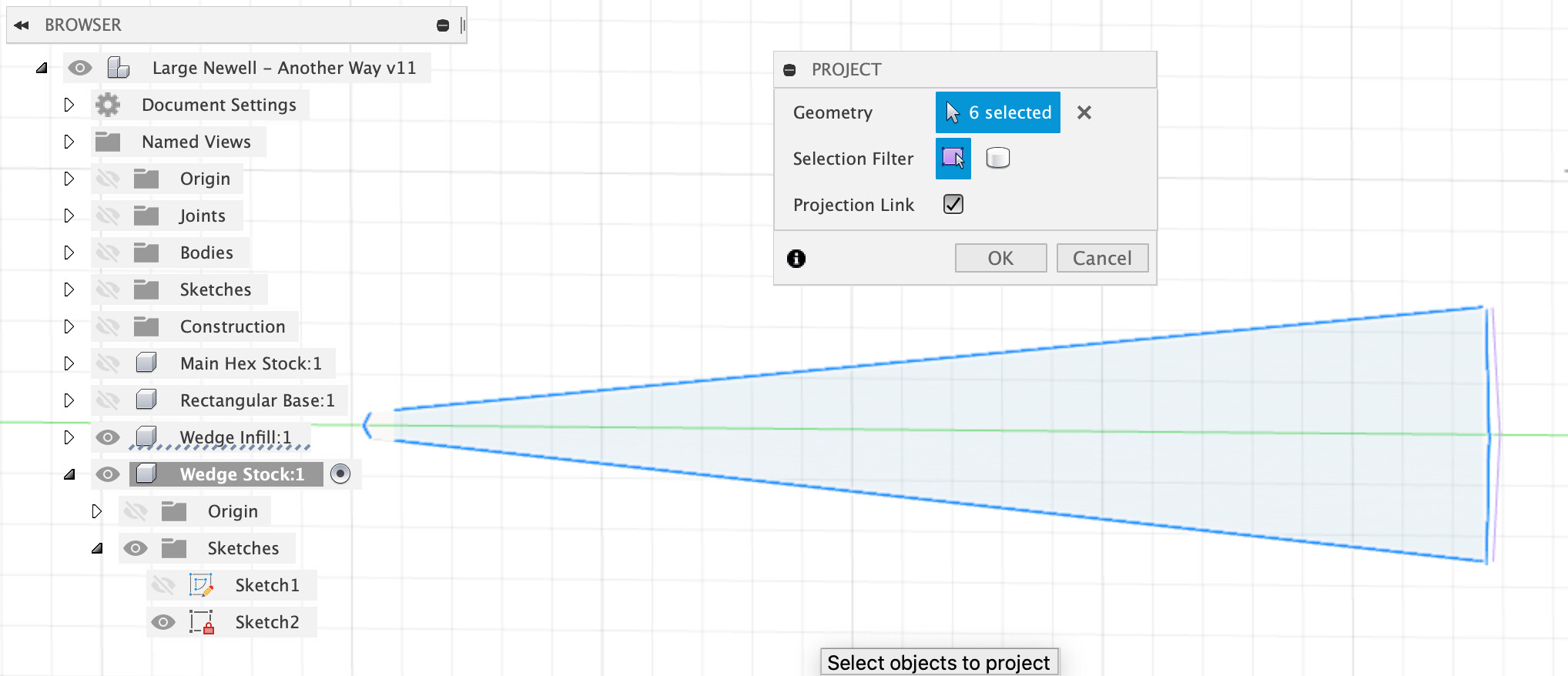
The wedges need machining too. First is the wedge stock component, this has two bodies, one is the starting stock to cut from, the second is the part-machined wedge ready for glue in to the hex. There a sketch with the wedge outer contour projected from the first wedge body and Wedge_Stock_Flat_Extra around the edges of Wedge_Stock_Thickness.

Inside that I then borrowed your trick of slicing planes which are offset Wedge_Stock_Face_Extra above the flat faces of the finished wedge to chop the stock body down to the machined item we want to glue in.

It seems over complicated, and it probably is, but it seems to work.
The Wedge From Stock CAM setup has the wedge stock flat, Z zero at the spoilboard (or whatever you mount the stock on) and X axis along the wedge. I assumed that you’d probably have the grain running along the long axis of the wedge.
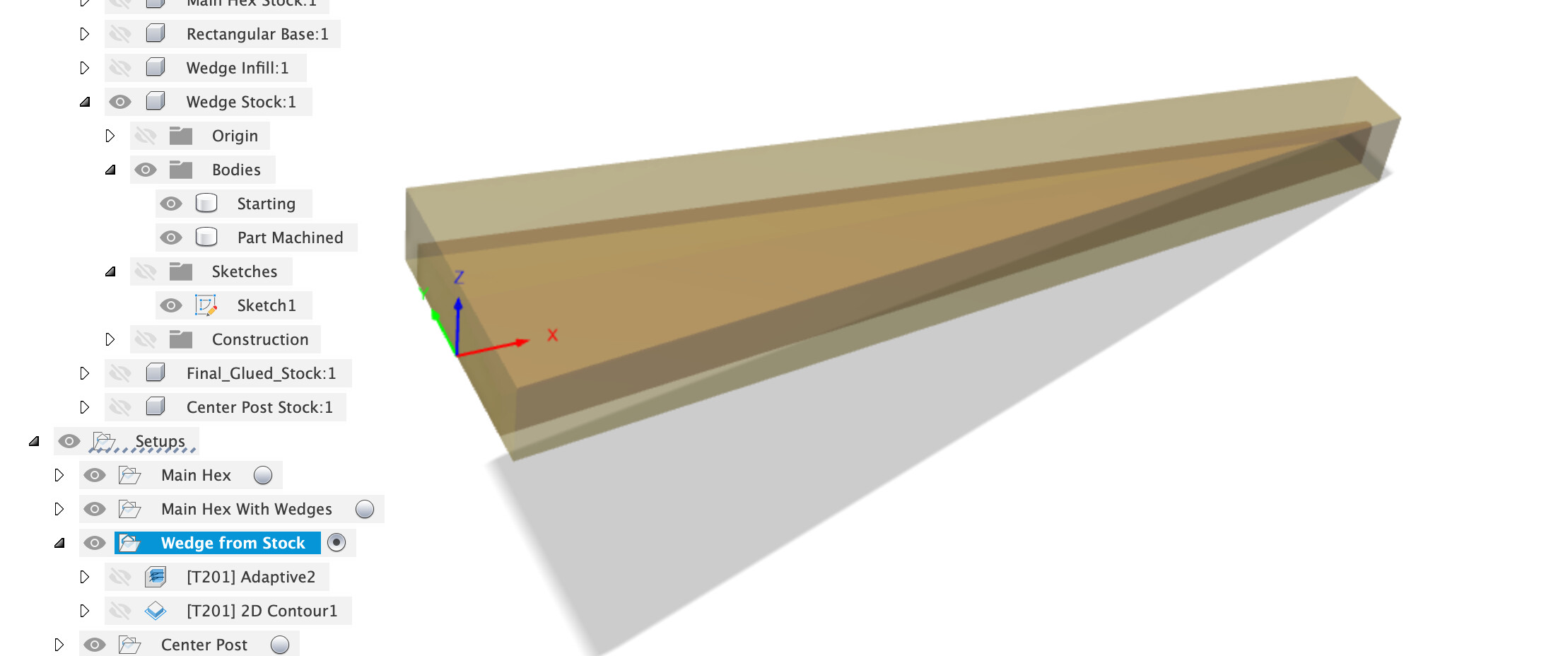
There’s then an adaptive clear

Followed by a contour around the edges, which has tabs in it, you may or may not want those depending on whether you’re blue tape & glue or just clamping down a larger bit of stock.

So that leaves us with a roughed out wedge with some extra stock left on the face, tip and root for glue in, hopefully.

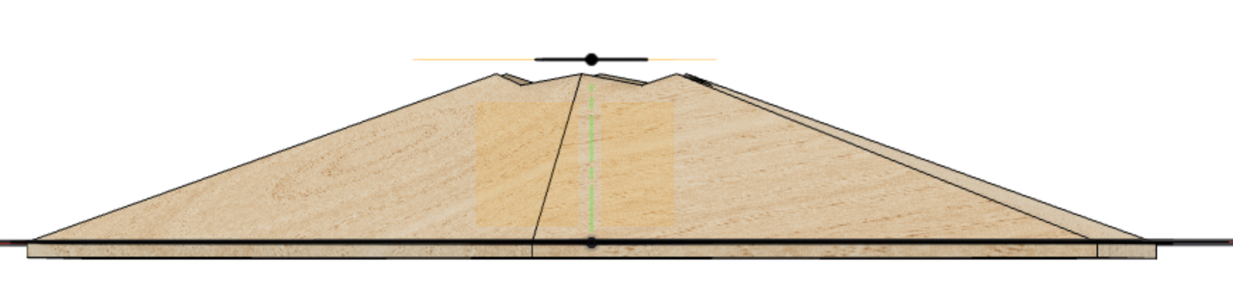
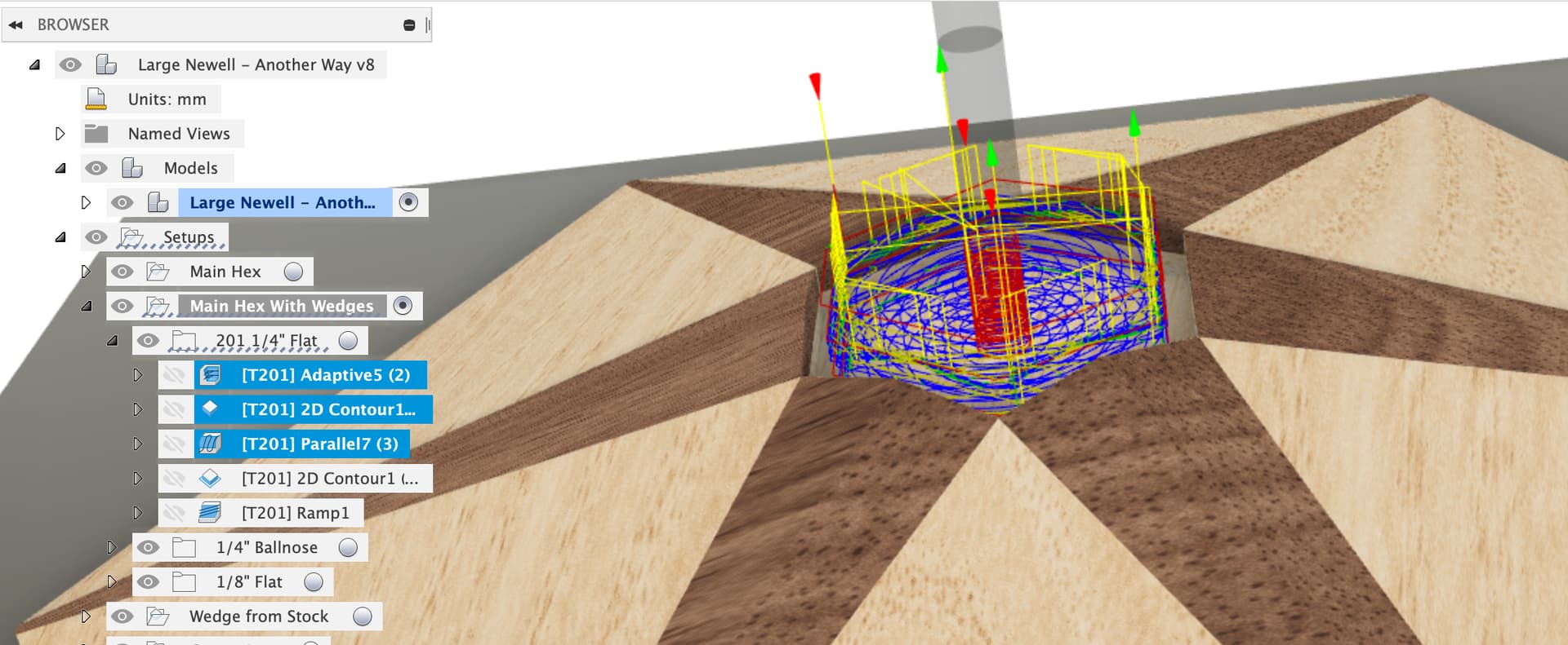
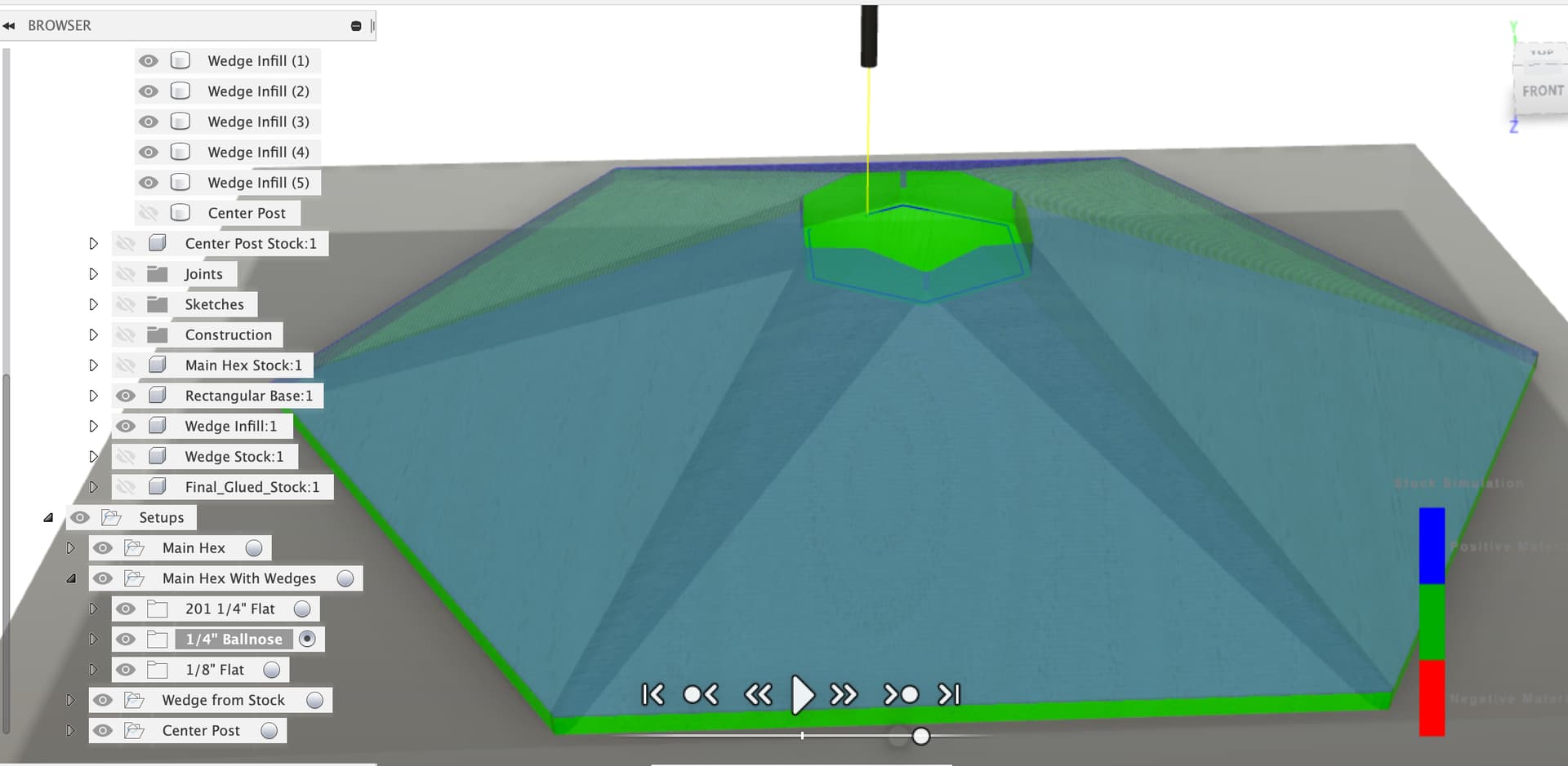
Once the wedges are all glued in we can go back and do the rest of the machining (as you described earlier). This setup has the same rectangular board and zero point, but this time all the wedges are included in the body selection, but not the center post.

Stock is another solid chopped down with cutting planes offset from faces by Wedge_Stock_Face_Extra to give us the extra from the glued in wedges.


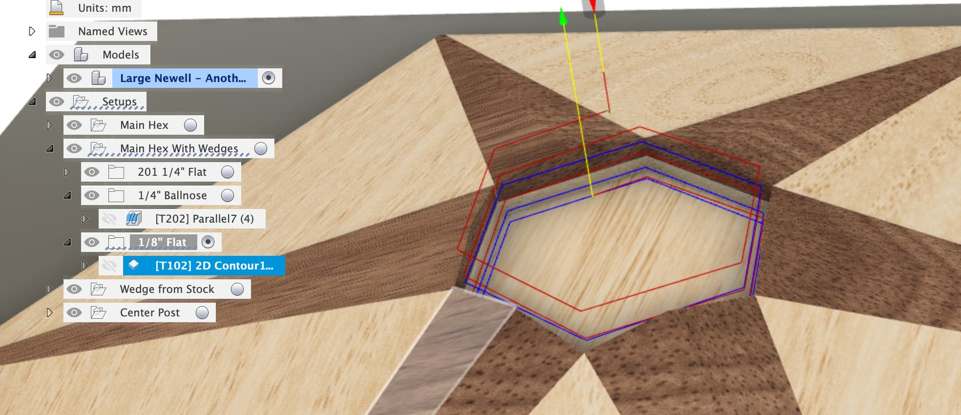
First set of CAM paths on the 1/4" straight cutter. We clean up the center post hole with an adaptive clear (there’ll be some air cutting here), a contour around the inner edges and a parallel along the bottom.
Then we run around the outer edge with a contour
And then we do a ramp with a little stock to leave to rough cut the hex and wedges down close to final dimensions. This one might be fun to watch.

Then it’s the 1/4" Ballnose to do the finishing pass on the main hex and wedge faces, play with the stepover on this one to adjust surface finish, or use a larger diameter cove cutter.

Finally the 1/8" flat cutter to give us a small radius on the inside corners for the center post.
It’s hand sanding now.
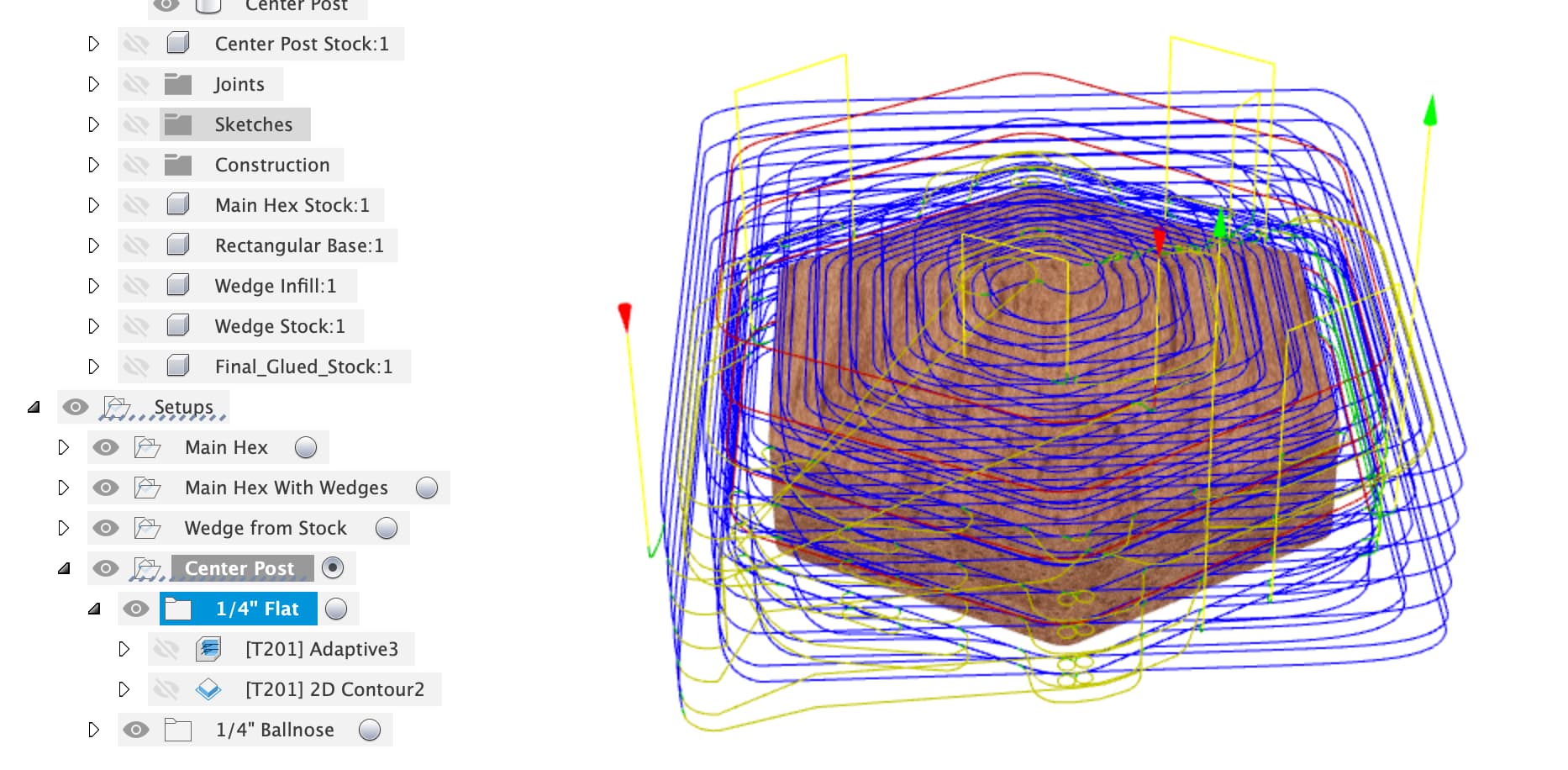
Last setup is the Center Post, there’s a stock object of Center_Post_Stock_Size and Center_Post_Stock_Height.
Simple setup of the stock and body with X, Y, Z zero in the bottom corner

1/4" flat cutter to do an adaptive and contour
Then the 1/4" ballnose to ramp round the top to reduce the sanding for the top pyramid part.

Here’s the F3D file, have a poke around and let me know if you’ve got questions.