First project - Hexagonal staircase newel cap

There are a couple of concerns with high spindle speeds:

  • brush life
  • inability of machine to accelerate to cutting speeds necessary for higher spindle speeds
  • increased vibration
  • increased rubbing/heat

Folks should work up to what is suited to their setup.

1 Like

OK, so I ran the first adaptive clearing pass on the main hex:

While it was cutting, I noticed that it took the top down early, and then went some cycles where it was cutting air above the top it had taken down.

And indeed, the result so far is that the top is only 34mm high, which is 2mm too low (finished top should be 35mm high).

And, you can see in the corners, which should be sharp:

That they are flat:

I highlighted one of the flat spots

Any ideas what’s going on? Here’s my file if you’re willing to take a look:
MDF Save.f3d.zip (1.7 MB)

And the .nc file:
MDF_MainHex1_Bit201.nc.zip (361 KB)

Here’s a timelapse of the cutting: MDFHex.mp4 on Vimeo

And here’s a close up after running the 1/8" ballnose and ⅛" end mill bits for wedge slot clean-up:

Hmm,

I looked at the Fusion CAM and the Fusion simulation leaves the peaks, I also tried the .nc file in ncviewer and it seemed to be correct as well (but I’ve not used it very much).

Is there any chance you ran out of Z travel?

@WillAdams any ideas from the gcode whether the shape that got cut is what’s in the file please?

1 Like

Well, yes, now that you mention it, it is probable that I ran out of clearance height (53mm). Add the 19mm of rectangular board under Z-zero to that and you get 72mm and I think the PRO only has about it 75mm of total travel.

I guess I need to reduce clearance height, right? With my raw stock coming in at 38mm I could live with clearance height to be nearer retract height.

The small corners on the outside edges, could they be spread farther apart slightly wider to fit a 1/8th end mill?

It’s odd and I don’t understand what’s happening here.

Normally if you ran out of Z travel you’d lose steps going up and then everything after that would be lower by whatever the missed steps amount was. In this case it’s just a few parts, early in the toolpath that are lower than where they should be.

Edit - Did the tops get machined off or just snapped off? MDF does tend to delaminate in small parts like this.

They definitely got machined off. I was watching as it happened and couldn’t believe it. They got machined off and then there was a bunch of air cutting above them. I don’t know if that’s noticeable in the timelapse video since there is no sound and Sweepy is in the way.

They could and I considered that, but my design is to have a thinner reveal on the vertical edge. Otherwise, the cross section would be square and actually look fatter given it sticks out a tad more than the main hexagon.

I do have a smaller end mill coming, but it was child’s play to chisel out the remainder in MDF and should be at least straightforward in Narra (kind of like mahogany in color, texture and hardness, but ecologically harvested).

1 Like

While waiting on understanding my top point clipping, I went ahead and milled a wedge. Fits really well, as expected. Since these are cut out of ebony, I’m trying to waste as little wood as possible, which in this case means rough cutting on the bandsaw. So, I don’t need to cut the “back” edge (the edge that sticks out into the center hex pocket). I’ll play around with it in Fusion, but is there a quick way to tell it not to mill that edge? That will help me with a jig to hold the raw piece in place.

1 Like

[quote=“Smorgasbord, post:90, topic:34301, full:true”]
While waiting on understanding my top point clipping, I went ahead and milled a wedge. Fits really well, as expected. [/quote]

Great, that’s good news.

Indeed, ebony is a wood we want to minimise the conversion to dust ratio…

There are ways yes… Basically we adjust the stock and then restrict where Fusion can send the toolpath by selecting boundaries for the adaptive clear. Then we use an open contour instead of a closed contour for the outer contour cut.

Here’s the file, I can explain a little better tomorrow.

I ran the gcode in Camotics and I can’t see anything wrong with the main hex adaptive clear which is confusing me.

Large Newell MDF Save v1.f3d.zip (1.7 MB)

I tried replicating what you did, but my adaptive clearing toolpath is empty.

I did move the origin to one of the corners of the finished piece, since I decided to have my starting point be in a corner of the finished piece so I wasn’t dependent on cutting raw stock exactly. Actually, since I’m cutting these out of a longer rectangle, each bandsaw cutout will be like this:


The shaded area is the finished wedge piece, the larger outline is the raw stock blank I’ll have off the bandsaw. I’m getting 4 wedges out of a 1.5" x 12" piece of ebony that I’ve resawn to 10 mm thick. I could do more by tilting the wedges, but I want the grain running lengthwise along the wedge spine.

I don’t want to mill the left hand side of the wedge since that will register against a wall in my holding jig, and that edge isn’t critical since it gets milled off after assembly anyway. At the far right of the blank the jig is more than ¼" away, so it’ll remain for registration. The lower left corner of the blank will be a right angle, but I can’t jig that since it gets cut away by the milling operation. But, I could put a blank in in the jig and zero off that lower left corner for X&Y, and then register Z at the bottom of the jig separately.

So my raw stock looks different. I tried modifying it, but Fusion has the sketch as one operation so I couldn’t just change a part of it.

BTW, I did notice in your file that the edge contour operation has some generation warnings:

Here’s my latest file, which has a number of changes from what I uploaded last that I’d like to not have to try to remember to replicate:
Large Newell v19.f3d.zip (1.6 MB)

Thanks, as always.

Also I just got a Niagra CB430 1/16" dia bit. It’s got a cutting length of 0.25". It’s 4 flutes, which isn’t ideal for wood, but I’m thinking for clearing out some of the wedge pockets it wouldn’t matter too much.

I tried copying the Pocket and Parallel toolpaths, then editing for this tool (which I added to Fusion), but neither seems to do what I want/expected. Suggestions?

Right,

I thought it was worth fixing a few things now that I better understand how you want do the expensive ebony stock so I went back and edited the main sketch in the Wedge Stock component. You’re right that Fusion doesn’t capture history within a sketch but the sketch can be edited and Fusion will try to stitch the history back together afterwards.

One thing that really helped me to understand what was going on when I edited sketches and broke stuff was when I saw an explanation of how Fusion stores the models which went something like this.

There is no model of your thing in the F3D file, it’s not like an STL which contains an object. Instead Fusion stores a list of instructions (the history bar) which, when followed in sequence, allow it to construct the thing(s) you told it how to build. History is built up of atomic actions such as Extrude or Split Body, sketches are stored as complete elements.

One consequence of this is that if you go and delete from a sketch a line that was used as a selection for an extrude later in the history, Fusion throws a warning and says “broken reference, using cached things” because it can’t follow the instructions start to end any more.

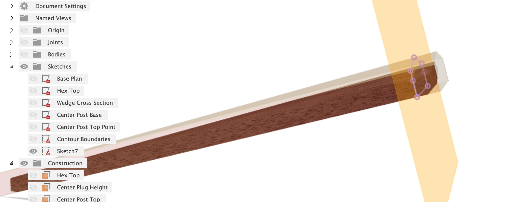
But back to your model, into the sketch in Wedge Stock.

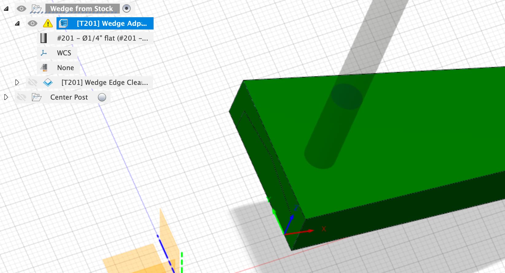
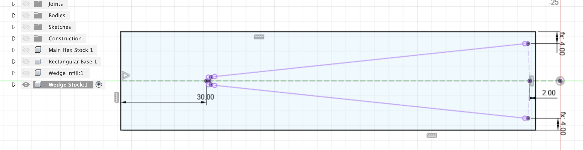
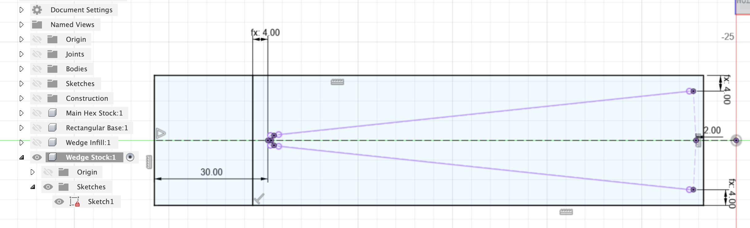
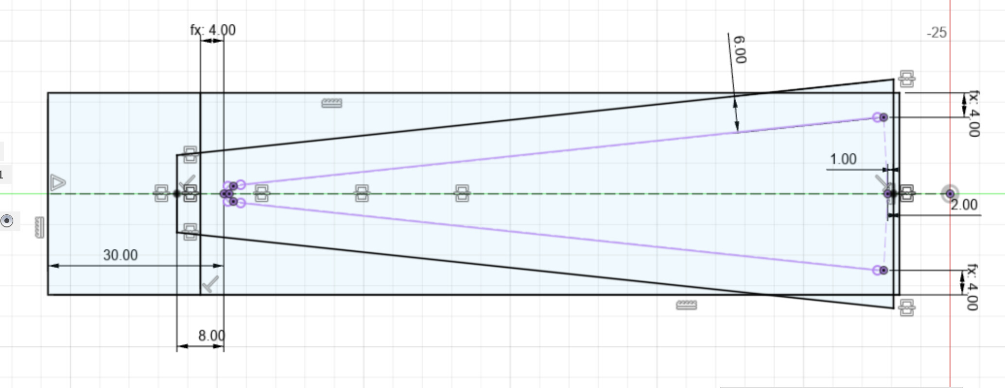
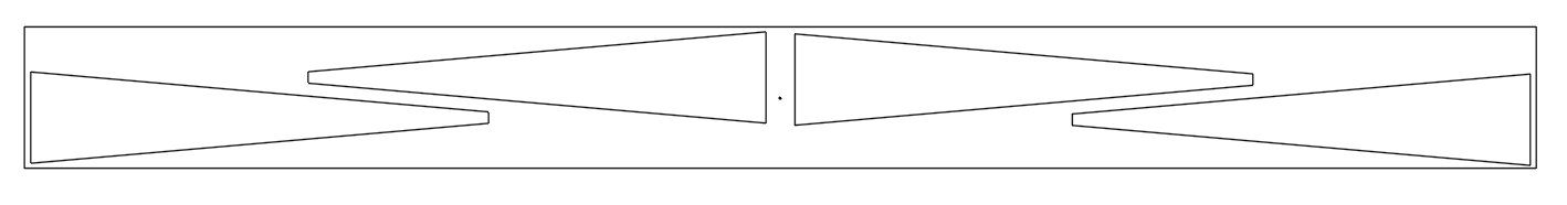
First I deleted everything and re-projected the outlines of the wedge piece, then I drew a square box around it to better represent all the extra stock you don’t want to chop up and the square lower left corner you indicated. Now we can work to minimise the amount of non-wedge stock we turn to dust. I set the sides Wedge_Stock_Flat_Extra away from the widest corners, the back 2mm from the rear face (might not be enough? up to you) and the front well away from the nose of the wedge.

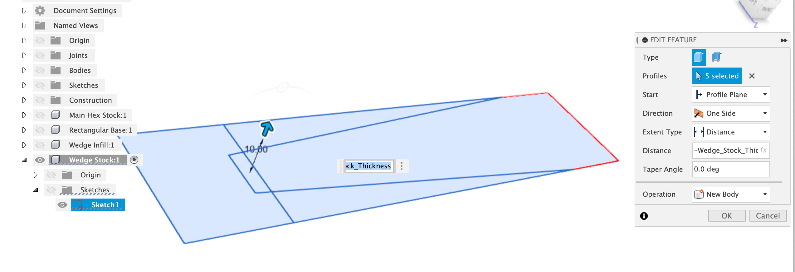
I then updated the extrude to have this full square shape

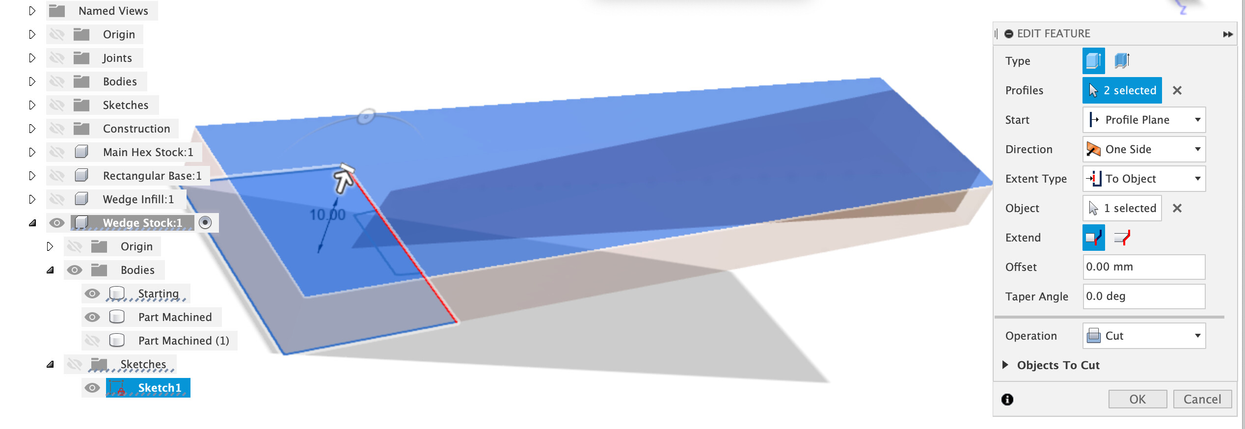
Next up, chop the long nose off the wedge blank to minimise the stick-out from the hex and how much expensive stock we chop up. Single line across the front at Wedge_Stock_Flat_Extra.

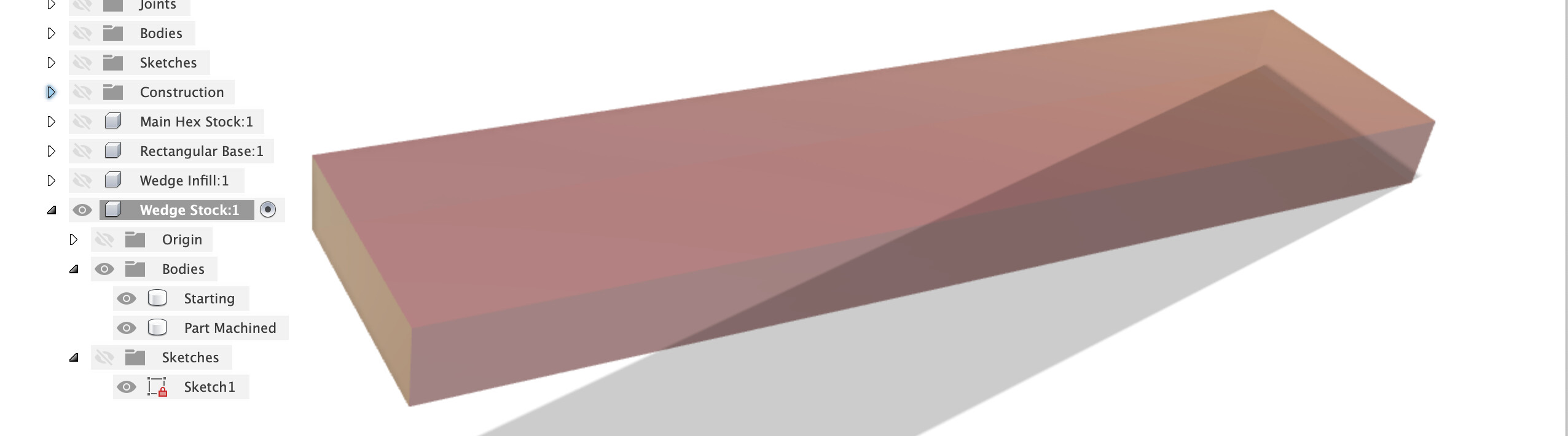
Which is then extruded in Cut mode through the Part Machined body

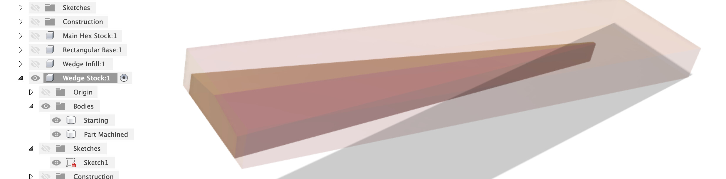
We’ve now got the bigger stock and all the ops as before to trim down the part-machined body.

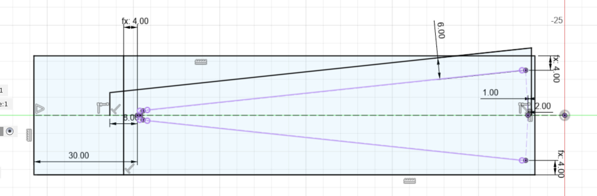
The remaining work in the sketch is to set up some boundaries to contain our toolpaths with. I drew two verticals from the mid-line and a parallel side to the wedge, that’s set 6mm away which is about right for the cutter size we’re using.

I only drew half of it because I’m lazy and like to mirror things instead of drawing them.

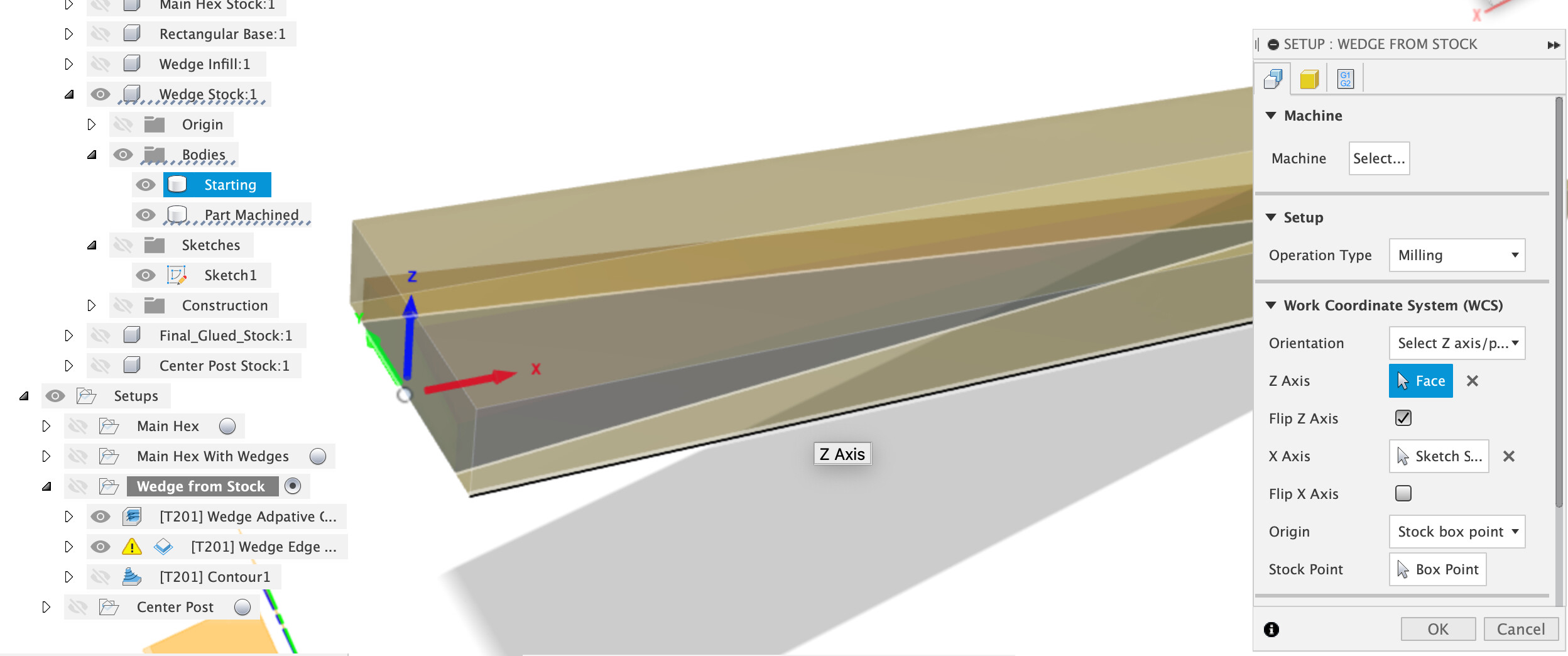
CAM setup using starting and part-machined bodies as the stock and body, I put the zero point in the middle of the back vertical face of the stock. I wouldn’t bother with the bitzero for this, I’d just draw a line on the stock in the middle of the wedge, stick a V bit or 1/8" cutter in the machine and line up on that in X, Y by jogging, zero them both and then use the bitzero to set the Z zero off the spoilboard or jig base. Do whatever works for you though.

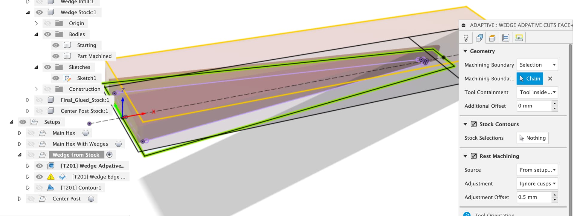
Now the adaptive clear, we will use the trapezoid we drew in the sketch as a machining boundary with “Tool inside boundary” (which is why I left 6mm)

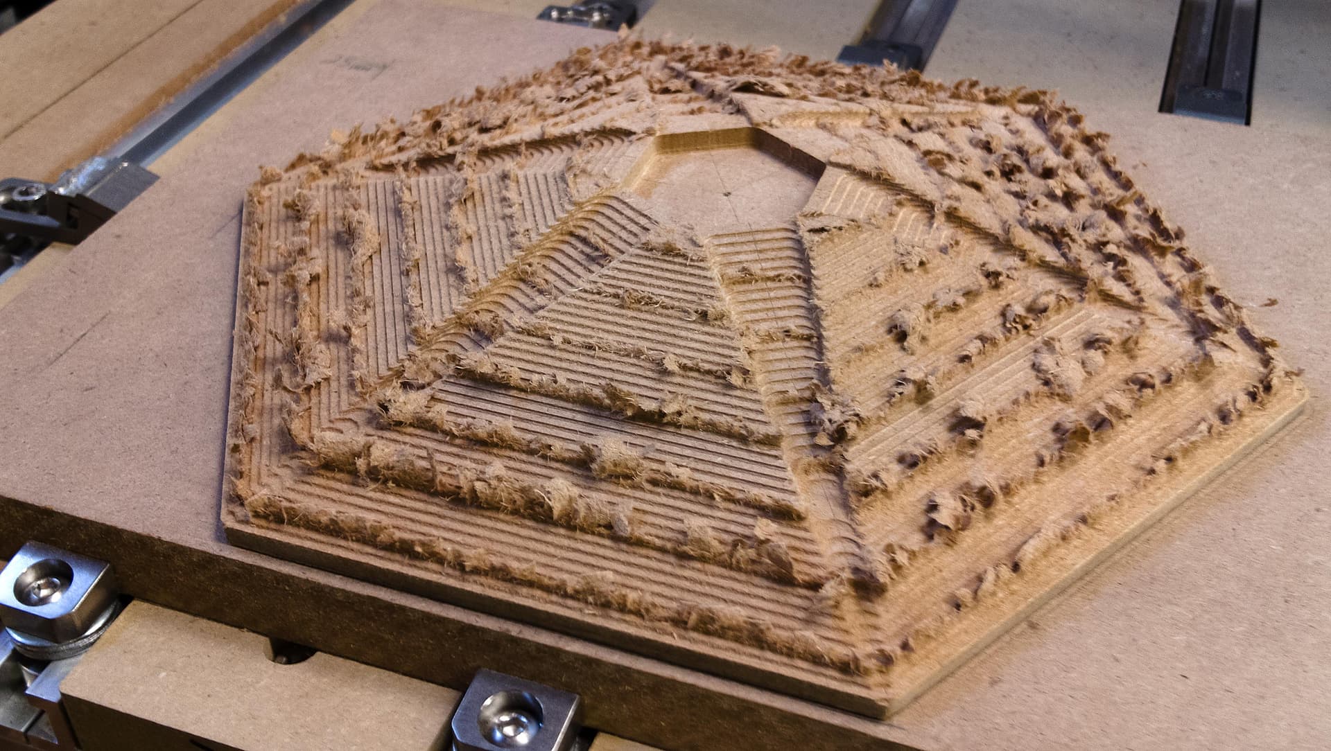
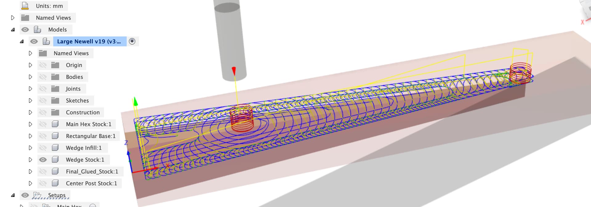
That gives us the adaptive clear constrained to what we want to cut

This is the bit where I get to go back to school and get a D in maths for being a dunce, I thought this was “interesting” and forgot why.

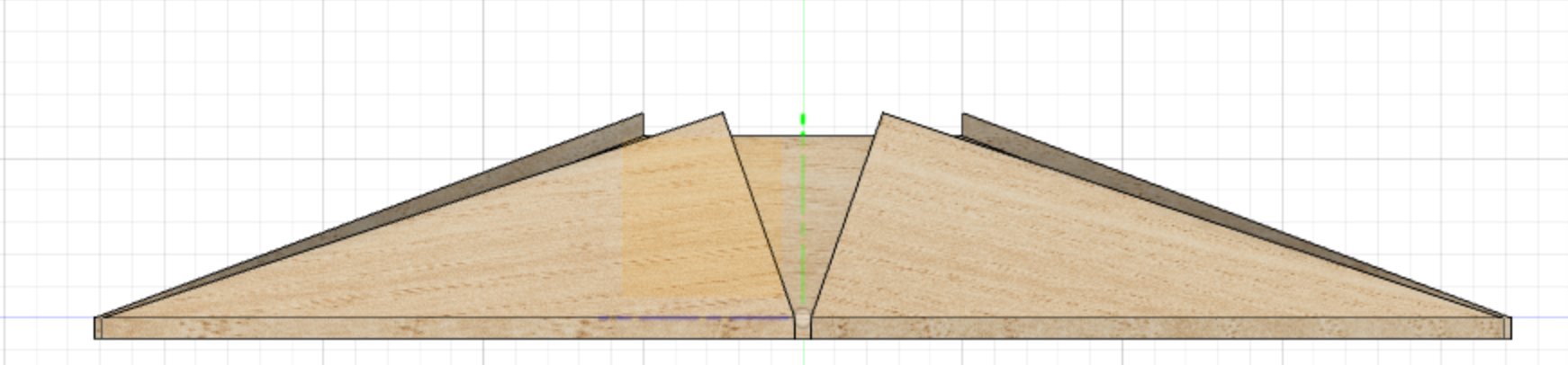
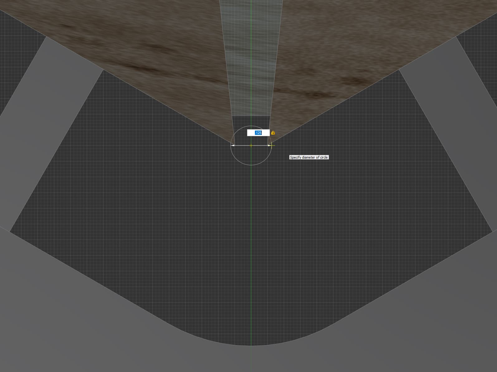
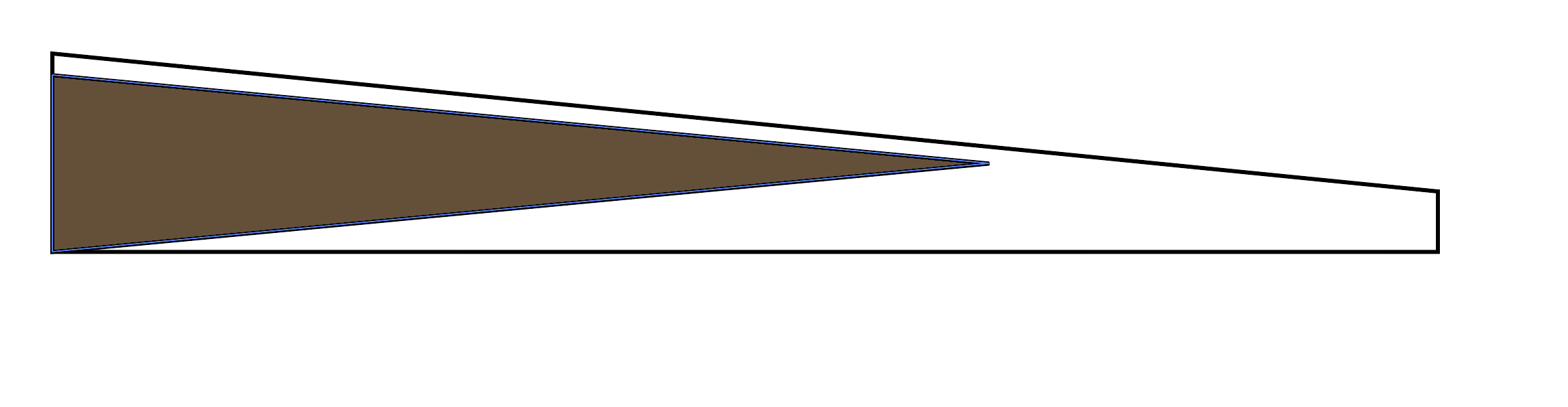
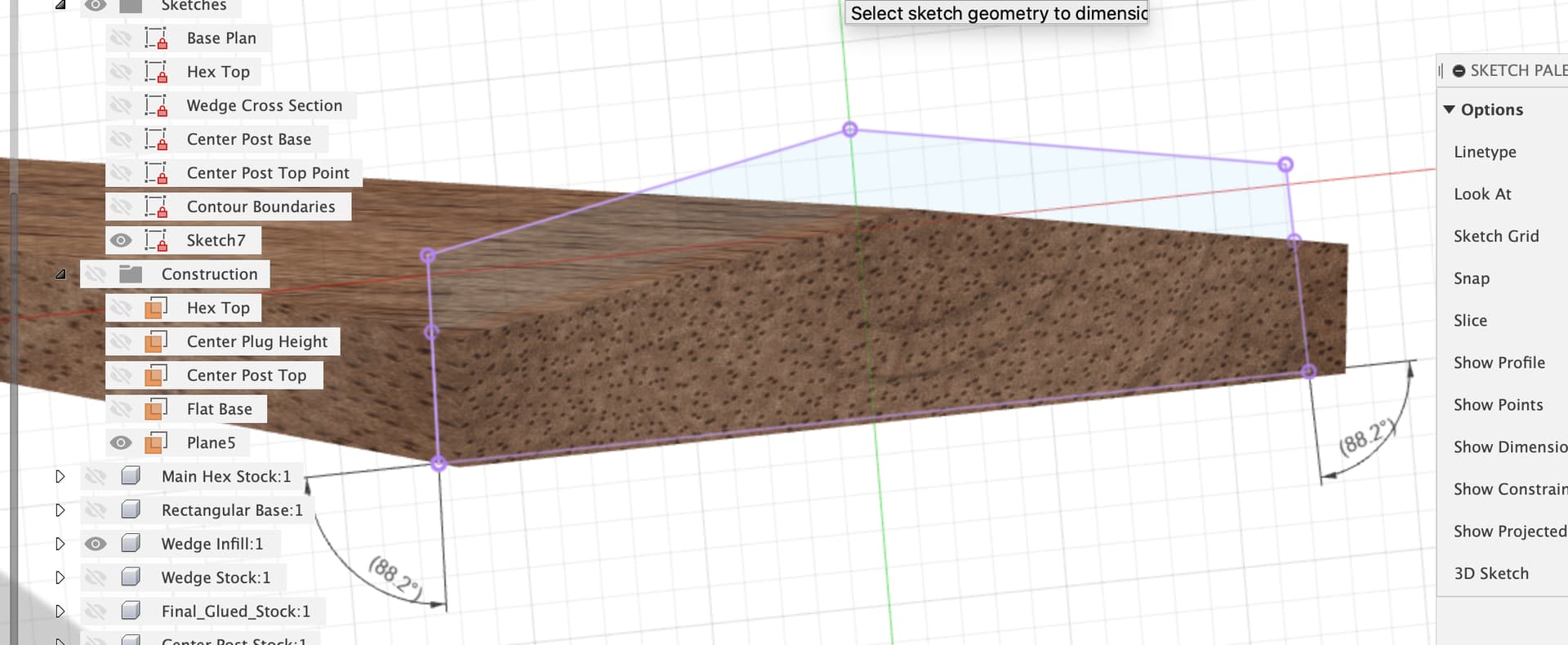
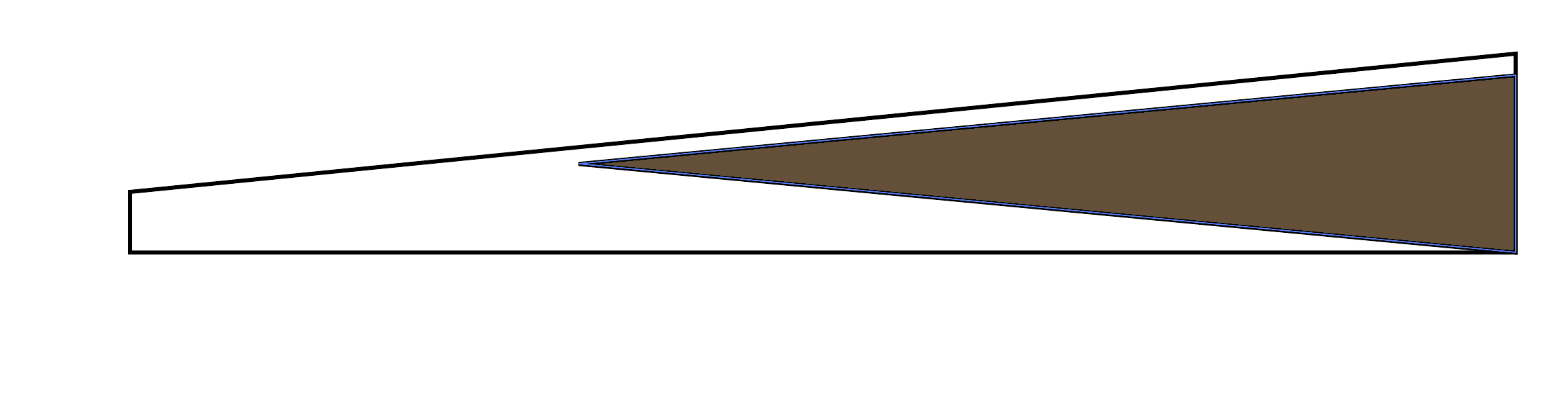
Creating a plane normal to the base of the wedge (which is how the cutter sees the workpiece) and then doing a project - intersect of the wedge or wedge part machined stock into this sketch -

We can then ask Fusion what the angle between the base of the wedge and the ‘vertical’ side walls is and discover that we are 1.8 degrees off vertical.

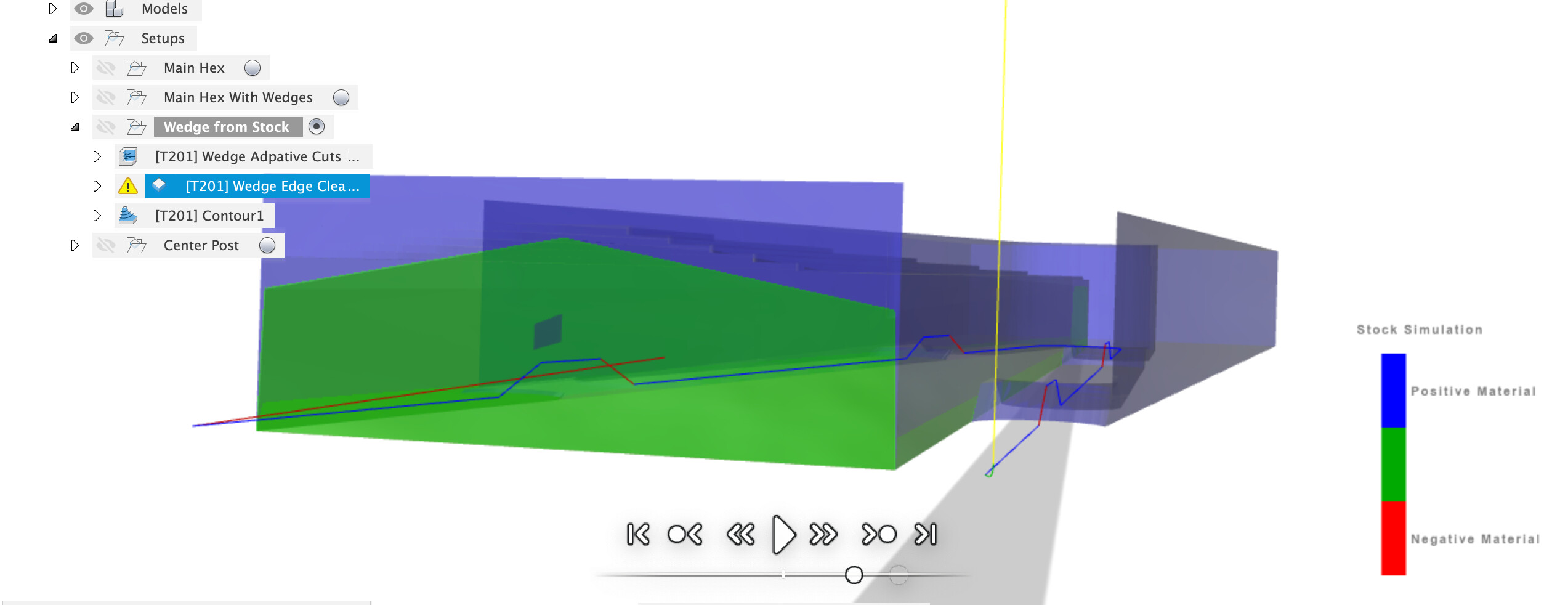
This makes sense when you realise that the walls are ‘vertical’ on the base hex but that for any line up the side of the wedge, normal to it’s base which is the sloped side of the main hex, that line is moving outward from center as well as up the slot walls cut in the base hex, so the sides slope in. I realised this when I got negative material warnings in the CAM simulation (always run the simulation).

This gives us two options, neither of which is perfect, but you could make both WillAdams and I happy by breaking out a hand plane to finish the wedge sides :wink:

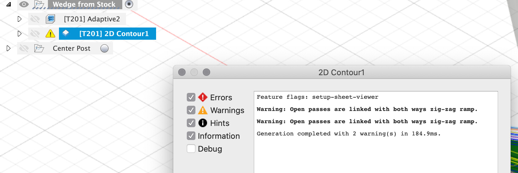
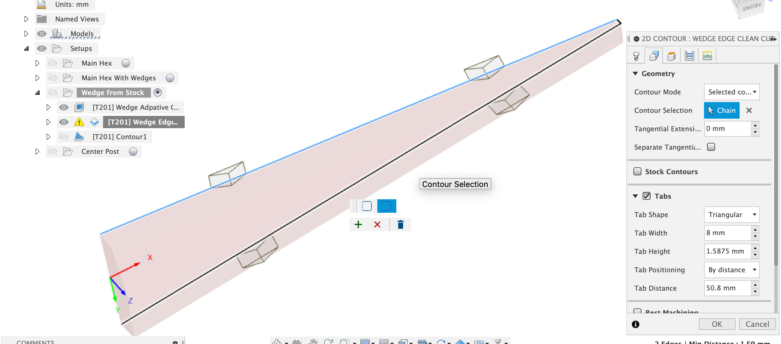
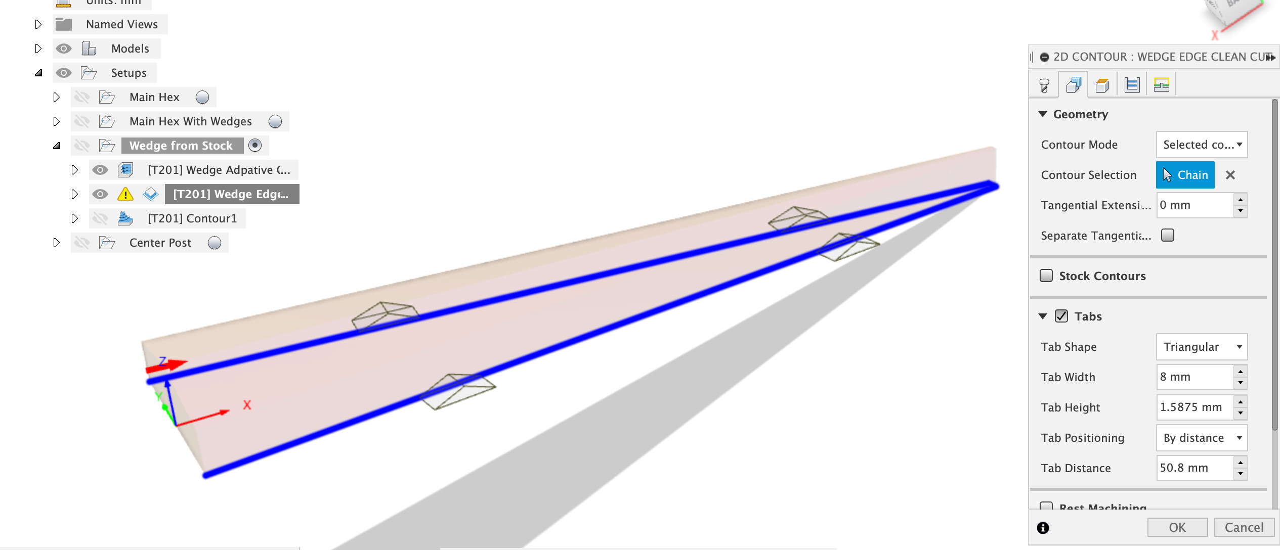
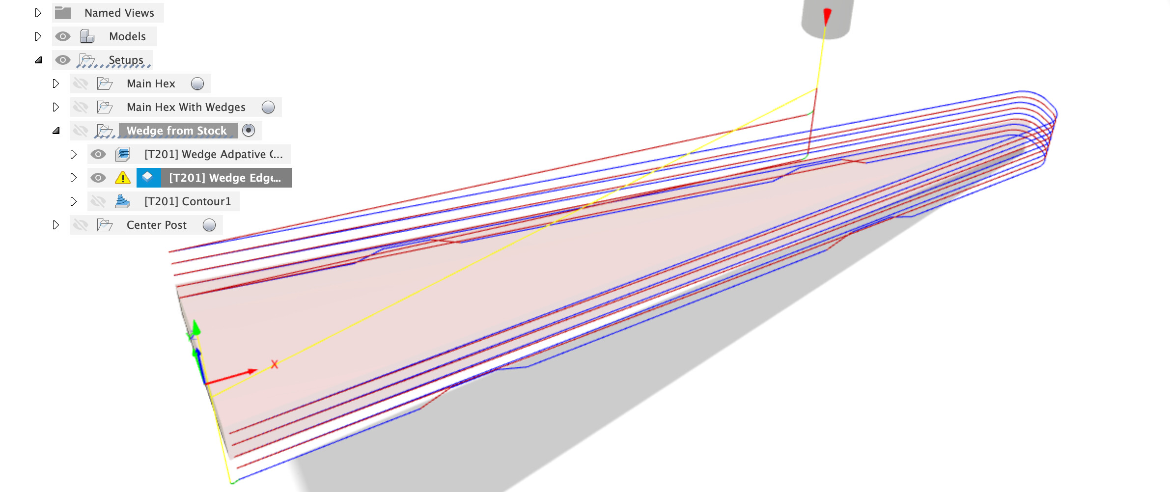
First we can use the 2D contour, select an “open contour” along the bottom of the wedge, on the three sides we actually want to machine.

Select the contour of the base, click again on the contour, select “open”, click a second edge, click + to accept.

Now we have an open contour running around the 3 sides we want to cut, yes we get a both ways warning in the CAM, meh.

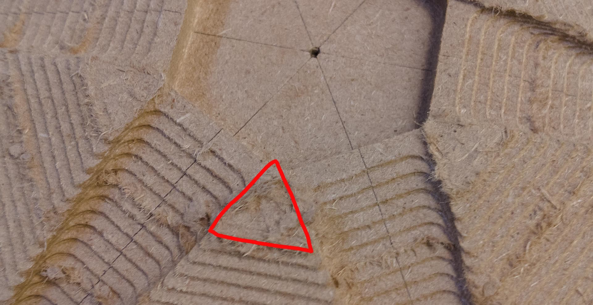
Problem is that this cuts at 90 degrees to the Z plane because your router bit is straight. There is un-removed stock after this contour toolpath.

Option 0 - try it in the slot, see that the top binds in tight anyway, say you don’t care and the glue will fill the gap anyway and forget we ever saw this

Option 1 - break out the hand plane and give the sides of the wedge a slight dovetail to sit in the slot on the hex

Option 2 - for the OCD amongst us, cut the sides closer to the angle we actually need on the CNC

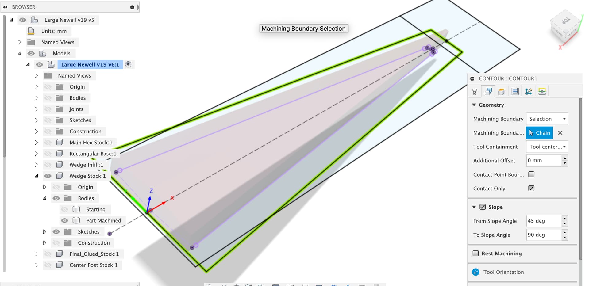
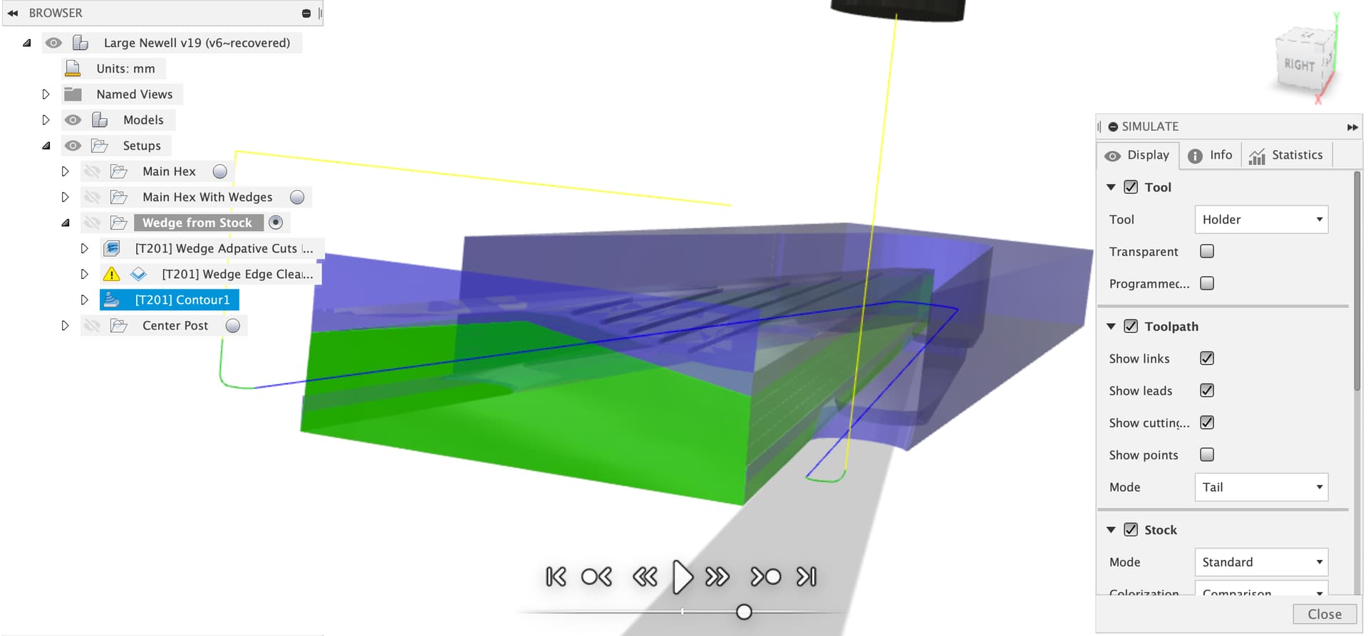
For option 2 we can use the 3D contour toolpath with the toolpath constraint we used in the adaptive clear to keep it to the sides we want cut, note I’ve also constrained the angle range to keep it off the wedge top

If we keep it 2mm above the model bottom
Screenshot 2021-08-23 at 19.47.40

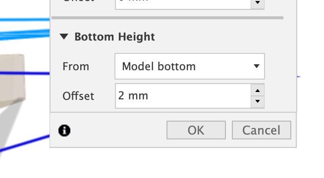
Then we even get to keep the tabs from the contour (the 3D contour doesn’t seem to do tabs)

That walks down the walls giving the slight taper (assuming we’re above the min step resolution of the machine which I think we are)

Updated Fusion file

Large Newell v19 v7.f3d.zip (1.7 MB)

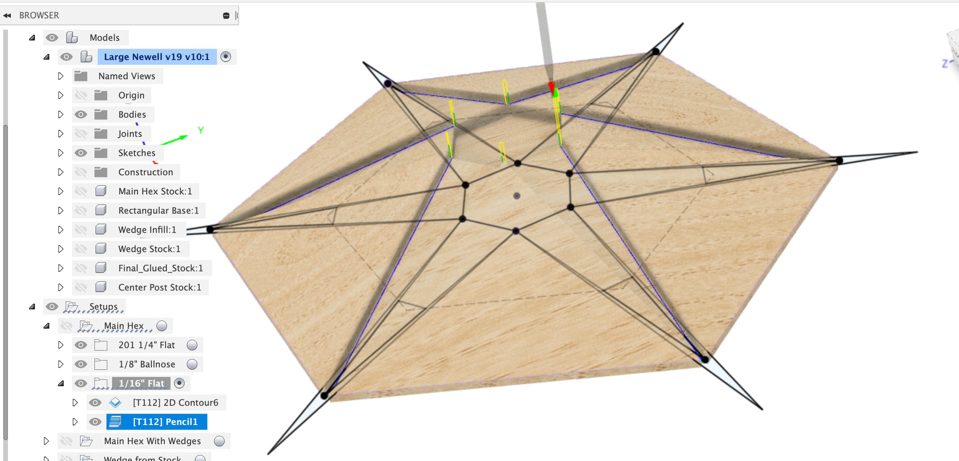
I still don’t know why your toolpath chopped the top of the main hex.

1 Like

I just used the Carbide 1/16" bit to try out the toolpath with and it did do some weird stuff on the pencil toolpath.

The pencil toolpath is the only one I’ve found that can run down that wedge slot wall in a single smooth run, not sure if I’m missing a much better Fusion option here, @Julien any ideas on a better toolpath for this?

I went in and drew some wider toolpath boundaries for the pencil toolpath and, after spotting that the pencil stops when it gets to Z=0 and doesn’t cut the notches, put in a 2D contour with a few step downs to open those out first.

Here’s the file

Large Newell v19 v11.f3d.zip (1.9 MB)

1 Like

Thanks, I’m looking at your file now.

I also have a small piece of glued-up MDF, so I’m going to stick that in the center and try the main hex milling operation again to see if it still cuts too deep or whether that was some kind of non-repeatable oddity.

1 Like

Try regenerating the toolpath and re-exporting it just in case too.

Yeah, I’ve been updating User Parameters all along anyway, so my SOP is to regenerate whether Fusion says it needs it or not.

1 Like

I still need to actually look at the file to see, but my raw stock isn’t symmetrical because of the way I’m cutting the wedges out of the blank.

One thing is that I’m going to have almost no clearance of the finished wedge from the right-angled corner of the raw stock. This is important because the angled cut I make on the bandsaw won’t be exact and is limited by the width of the raw stock. Here’s the full blank plan (not to scale):

If you have a better idea for cutting out of the blank (1.5" x 12.375"), that’s be great, but otherwise my idea was to cut the blank in half at a right angle and then slice through each at an angle. This way I have the same size and configuration of blanks to put in a jig on the table.

The difference is I won’t have that 4mm of cushion on both sides and I really think I should register zero from the tight corner to keep as far away from the other hand-cut side as possible.

For the blanks I’d suggest cutting out a template from MDF on your Shapeoko which is just a couple of mm bigger on the sides and sticking that to the real stock to guide as you bandsaw out as many wedges as you can get from as little stock as possible.

You only need enough extra stock to ensure that the stock exceeds the cut piece on all sides. Given the value of the stock I’d make an MDF carrier jig for the stock which you can zero from repeatably and easily, as per the main hex. If you do that it’s easy to mark the centerline of the wedge on the carrier and get it aligned. The only alignments that seem to matter are

  • thick end of wedge flat against jig
  • centerline of wedge in line with other axis on machine
  • centerline of wedge approximately in line with the stock grain

I would personally go Scotch tape and superglue for this to avoid having lots of extra stock on the sides, then you don’t need tabs or any other messing about, just run the toolpaths at a relatively low Depth of Cut to keep the forces down and you should be fine.

Edit - you could use a V-bit to engrave the outline of the stock on the MDF jig plate to make aligning really easy.

1 Like

Funny, I’ve done that in the past with Illustrator and paper.

Good idea, assuming my first piece cut doesn’t go into the jig board slightly.