Since I’m more of a traditional woodworker looking for more accuracy, I was originally thinking of getting a Shaper Origin, but this new hexagonal staircase newel cap project seems better suited for a CNC like the Shapeoko Pro.
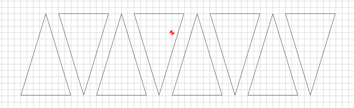
I drew the design out in Illustrator as I always do. Then I built a quick prototype using traditional methods (dedicated sled for the dark ebony wedges and miter sled for the triangles), but quickly found out that with 12 pieces even if I’m off on the angles by only 1/10º, I’ll have a gap larger than a full degree, which is completely unacceptable.
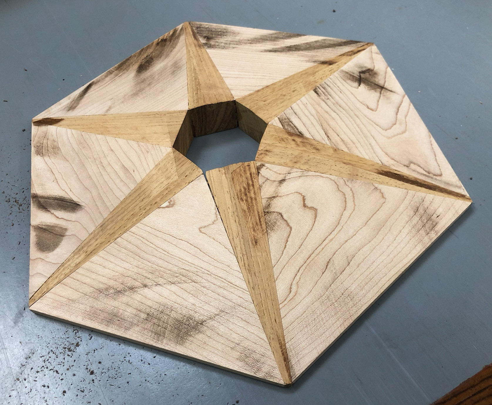
Pieces will be Ebony and Mahogany. My stock is 1.5" thick and I cut the pieces out, then glue them up. Then I run the glued assembly 6 times through the tablesaw, with the piece on each edge and the tablesaw blade tilted to provide the bevel.
My questions:
Is this project within the normal capabilities of the Shapeoko Pro? I’d need good double stick tape or secure the pieces up from underneath the spoilboard to secure them.
If so, should I still cut them out in 2D fashion, glue and trim, or should I cut them directly to the 3D size on the CNC? I might design them to leave excess on the face so I could still do final trimming on a disk sander.
Here’s where I think the Shapeoko will shine: I have six hexagonal posts to cap, in 3 different sizes. Since the posts were built with traditional methods, they are not true hexagons. The 8" across post, for instance, is off by 1/16". I can put a piece of thin plywood on top of each post and then flush trim route that plywood to the actual shape. Then I could draw the pattern, adjusting it so that the corners line up and the ebony wedges have the same thickness, essentially hiding the imperfections in the larger triangles. In essence, I would custom build each cap to match the posts imperfections. Anyone else do anything like this?
I’m thinking of starting out with the Standard size Shapeoko Pro since I expect that most of the projects for which I want CNC precision would fit. And I believe I could always upgrade that to an XL or XXL later if I decide to dedicate that much shop space to CNC.
You’ll need to model the angles in 3D or work up a fixture to hold the stock at the angles necessary to cut it out
Sounds like a plan — I’ve taken photos of boards and imported them into Carbide Create so that I can lay out parts around knots and other imperfections
Note that while we had upgrade kits for the SO3 to XL or XXL (and an XL → XXL kit), we are not offering upgrade kits for the Pro or SO4 — too much of the machine structure has to be replaced, the upgrade would need to be selling the smaller machine and buying the larger.
it sounds like a perfect job for tape & glue workholding (= similar to double-sided tape, but much less messy and difficult to remove)
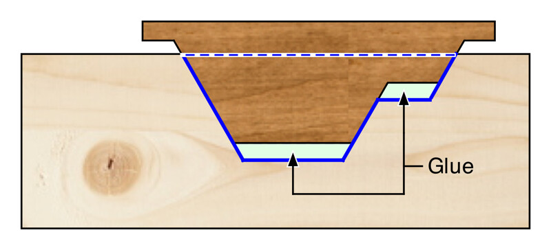
You could potentially carve this similarly to an inlay job: first cut the “base” (the set of six large triangles laid making the hexagon) in one go from 10"x10" stock, and then cut the “inlay” consisting of the inner “star” from another piece of 10"x10" stock. Not efficient in terms of optimizing stock (for expensive wood), but cutting all parts in one go will pretty much guarantee that all pieces will fit perfectly (rather than cutting individual triangles, and potentially cumulating tiny angular errors if the setup/jig is not perfect).
About the Shapeoko size: I went for the standard size myself, caught the CNC bug, and have then found myself in situations where I wish I had a slightly wider work area (deeper is not a problem, as one can utilize tiling techniques). So the XL may be a good investment if you think you’ll be adding CNC to your shop on the long run.
@Smorgasbord Bennet,
I’m also a traditional woodworker. I added the S03 a little over a year ago and it’s been a terrific addition. It’s not as well documented as your other tools - and there’s a LOT more trial-and-error to get the techniques that work for you, but you will find it to be an invaluable part of your solution arsenal. I’ve gotten to the point where my mind thinks about CNC solutions almost immediately. There’s something to be said for the accuracy and precision that you can get. Basically all those great things about routers without having to make the templates.
I purchased the XXL off the bat, and am glad I did. I seldom stretch the boundaries of my table (my wasteboard is 31"x31" - but when I do, I tile with little effort. Having the larger surface just makes the decision to use the tool that much more likely.
You could potentially carve this similarly to an inlay job
That’s a really interesting idea! Since this is solid wood I really want the grain running parallel the outside edge of each of the larger triangles, so my modification would be to start by making a glue-up of the triangles (basically six 60º pieces), when that’s dry bevel it on the tablesaw (or maybe cut the pieces so they don’t need the bevel), and then cut out of the assembly for the ebony wedge as inlays like you suggest.
The issue there might be that since the ebony runs to the very edge, and since the “A” surface isn’t parallel to the spoilboard, I’d either have to mill the bottom of inlay opening parallel to the beveled top accurately as well as cut the thickness of the ebony accurately, or else just make the ebony wedges slightly thicker than is needed and sand them flush after gluing them in place. The latter seems safer (and more traditional woodworking) to me. This also saves expensive ebony stock since it’s not an inlay, not a thick member.
As for size, ugh. The table in the shop where I could put the Shapeoko is only 35" wide. So, getting the XL would mean placement the table such that if I needed to tile I’d have problems with walls, and also that I’d need more than ⅔" of that table’s length as well, which potentially interferes with the outfeed of my tablesaw for long rips. And honestly, if I were needing this kind of accuracy for woodworking on big pieces, I’d probably rather shell out for the Shaper Origin instead.
I would think you could create the triangles all oriented next to each other on the stock - maybe even pointing in opposite directions. You could still do the inlay technique by creating beveled cut outs of each of them. The glue up would be trickier, but absolutely solid.
create the triangles all oriented next to each other on the stock
Yeah, that’s what I did using my tablesaw and miter sled. And, the triangles are 60 degree equilateral triangles, so it’s not bad to dial in enough accuracy. Cutting for the inlay before assembly is an interesting idea, thanks.
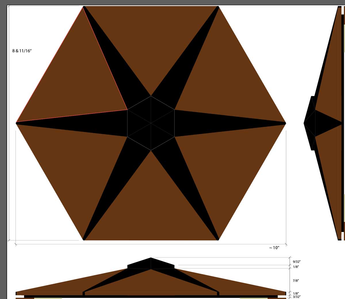
Actually, one issue I haven’t yet brought up is that my staircase newel posts aren’t perfect hexagons. I did create a 3/32" reveal for the caps (see above graphic from 2nd post), but they’re off enough that I think I’d want to tailor build the cap to match the post. The idea of cutting the triangles to match the posts and glue that up seems straightforward with the Shapeoko, and then cutting for the uniform ebony inlays seems the best solution. The triangles are big enough that 1/16" size different wouldn’t be noticed, and the wedges would all be identical from the Shapeoko, which IS important.
If you use the “wedge” technique for the inlays, they’ll be VERY tight. Make the pockets for the inlays accurate and true, regardless of the actual post dimensions, and manage the transition to the post’s inaccuracies in the base piece.
If you use the “wedge” technique for the inlays, they’ll be VERY tight.
Normally, I’d cut the wedges with angled sides, but to do that on a Shapeoko I’d have to use a “V” bit that’s very very steep, right? And then the potential issue is how much sanding is done afterwards - if I sand too deep then gaps appear. Unless you have something else in mind?
OK, I ordered the Pro Standard. While waiting for it to arrive, I thought I’d start getting familar with the software and try to lay out the inlay path in Carbide Creator. Assuming that I build the hexagonal “base” using traditional methods, my idea was to put a couple of cleats down on the spoilboard that align two of the edges of the base. I’d then move the base 5 more times to cut 6 inlay pockets per base. I’m doing this because the base will be intentionally imperfect to align with my imperfect newel posts. The idea is to register the inlay pocket to the nearest “point” of the hexagonal base, which the cleats will do.
Here’s what it currently looks like in Carbide Creator:
My question is: How do I get Z-axis movement into the toolpath? Remember the base is thick in the center and thin at the edges. I don’t want to cut all the way from the top down to the bottom for the whole path because that will cut my base apart. I want to cut a pocket that’s about 1/8" to 3/16" deep, but parallel to the beveled top surface of the base. How do I get to some kind of 3D view so that I can have the tool depth vary with radius from the center of the base?
Carbide Create is essentially a 2D/2.5D CAM program, so it can’t model 3D shapes or directly generate real 3D toolpaths. Carbide Create Pro (which you can get a trial version of) adds features for simple 3D modelling and toolpathing, that you could use in this case (one of the options is to model a 3D sloped surface)
Or you could use a different CAD/CAM suite that supports full 3D modelling & associated toolpaths (e.g. Fusion360 or Alibre3D)
Or you could use a wedge/tapered jig to hold your base, such that you could then program a simple “vertical” 2D pocket toolpath in CC. But of course that raises the question of how you would make that jig, with the correct slope (you could mill it, but that would require…some 3D software. So you would probably need to cut it manually)
I’m thinking, if you are going to use an “inlay” approach, you would probably also like to cut the inlay pocket using a V-carve toolpath rather than a simple straight pocket (because doing inlays in 2D pockets requires a perfect fit, and that’s likely to require more trial and error and tuning). And then the sloped jig makes a lot of sense, because you can’t v-carve on a sloped/3D surface anyway…
That’s probably clear as mud…
Will may have other ideas.
@Smorgasbord Julien is absolutely correct here (and is is also the local EDIT: GLOBAL, expert on inlays)…His point also addresses your concern regarding sanding away the tight fit. If the pocket has a matching sloped edge, the connection between base and inlay covers much more surface area and will withstand quite a bit of sanding.
Carbide Create Pro (which you can get a trial version of) adds features for simple 3D modelling and toolpathing
I was surprised to find out that the Pro package wasn’t included in the price of new machine. Maybe time to learn Fusion360.
Or you could use a wedge/tapered jig to hold your base,
I had thought about that, but given the size of the base, I’ll likely run out of vertical room under the gantry trying to make the bevel horizontal unless I cut holes in the spoilboard,
One question I’ve had about VCarve inlays is that if don’t mill them right then you might have a gap between bottom of the top piece and the top of the bottom piece. You’d need a gap-filling glue, right?
But, since this inlay is a simple wedge, as long as the angles match I can simply slide the wedge into the opening and push it as far as it’ll go. I’ll be trimming the center opening later anyway, so I could make the wedge slightly longer than needed.
Folks here have shown cursive script inlaid using the vcarve mechanism and it’s pretty flawless. @Julien has a great set of tutorials on it that you can look up (or he can graciously share the link to )
From the drawing in your original post I see the part is about 1" thick, if my math is right the jig angle would about 11° bringing the flat part to b milled at around 2" height, a Shapeoko has about 3" of Z clearance, that should work ?
That’s the beauty of vcarving for me, you make the female part slightly deeper than it should be (to account for glue, and for some margin), you make the male part slightly taller than it needs to be, then glue in the male part, it will stick out and then you sand or mill down to the surface of the female part surface. This allows one to not be very precise in the depth/height of the female and male part, as long as the wall angle is the same (that of the vbit), it will fit perfectly.
True! So if the jig approach is not practical, I guess you’ll need to do some 3D modeling and toolpathing. Happy to help modeling this in fusion if you need.
Julien, you’re right that the angle is low enough that the part should fit, even with me going to a 1.5" thick base now. But, getting the angle right is tricky since the angle isn’t one of the bevel angles on the triangle, it’s something in between the two.
I understand about the VCarve geometry; I guess the question comes down to how controllable the gap between the pieces if and whether your glue can span that gap with enough strength. Traditional woodworking glues don’t span well, but epoxies and cyno glues can.
I do think that since I’m making both pieces on the Shapeoko I’ll have enough accuracy, and like I said the simple wedge shape gives me an easy out on the fit. Are there any good getting started tutorials for Fusion? Otherwise, I’ll do the usual YouTube search…
Oh, and I still haven’t figured out the best way to make/attach the center piece, which is a hexagonal cap that to the completed base:
Originally, I was going to mill the center of the base with a hexagonal hole, clean out the corners, and insert the hexagonal cap like an extrusion. But, I think that leaves me open to gaps, even with CNC. It might be better to build the hexagonal cap such that it sits on top of the base, maybe screwed in from underneath the base or glued.
I could mill the hexagonal sides conventionally or with the Shapeoko. I would then need to mill the bottom with a recess so that cap only makes contact on the outside edges. Ideas for that? For the top, I could mill that conventionally, because on the CNC it would involve ramping accurately and would definitely need some sanding clean-up anyway.
Thoughts on the center cap milling would be appreciated, as always.
TIA
I learned the CAD part from this guy, it was an excellent start to make sense of the UI, and then once we master the basics/design principles, the rest is easy to learn as you go. The CAD part I learned by doing and with the help of folks here on the forum.
I have never been a woodworker so I tend to think in terms of “I have a CNC, it’s the answer, whatever the question is” (which is a bad approach obviously, but I just love CNCing stuff). So I would do that as a two-sided job