Yep, Ben’s been iterating quickly on the model and updating it a lot. It’s an interesting model because there’s a whole bunch of trade-offs which have no ‘right’ answer without a 5 axis machine to cut with.
1 Like
Looks like he might have changed the model since I played with it.
Yes. Here’s the latest if you’re interested in poking around:
LargeNewell v23.f3d.zip (2.0 MB)
I think the 1/16" end mill should be able to get reasonably close in. And, I don’t mind some hand work in the tight part of the wedge pocket.
Right now I just want to be sure I’m not going to create a stock market chart on my good stock, so I’ve got at least two more test mock-ups to cut to prove it out (one is to recut the already messed up test piece; if that goes OK, then try another from scratch and if that goes OK then probably another just to be sure it’s not a fluke).
I’ve already cut the final wedges out of ebony (and a full set for try-outs in some scrap wood), so hopefully I’ll get to test fit them in the pockets cut in one of those mock-ups. If I do have to recut the ebony wedges that’s not the end of the world. I am worried that the wedges don’t go to the full 25 mm width of the design, but we’ll see.
I mentioned the pulley set screws just because in the past they have been a typical root cause for such shifts (it’s either that or lost steps, but in your case I don’t see why such a shallow cut would produce lost steps). The setscrews should be nice and tight and have some loctite from the factory, but…you never know. Unfortunately, it is indeed a bit more tedious to check them on a Pro than a regular SO. You would need to disassemble the X motor (= release tension in the X-belt and then remove four screws holding the motor). If you do disassemble it at some point, the marker trick that Liam mentioned is useful (for next time you have a doubt that the pulley may have slipped). Anyway, it could absolutely be something else, but I thought I would mention it so that you don’t chase a ghost if this is in fact the problem and can be checked semi-easily.
I encountered some weird stuff here:
- Removed one end of the X-Axis belt, then removed the X-Axis motor.
- Tightened the two grub screws a bit (maybe ¼ turn each).
- Marked pulley and shaft for later examination
- Reassembled.
Then:
On Initialize, the carriage wanted to go the wrong way on the X-Axis! It didn’t really do that, and ended up just hanging out and making motor grunt noises. I rechecked the wires and same thing. then plugged and unplugged all the X-axis cables (not in the control box though), and somehow that fixed it.
After doing that, the repeat of the cut went fine
So, do I have some intermittent wiring issue?
1 Like
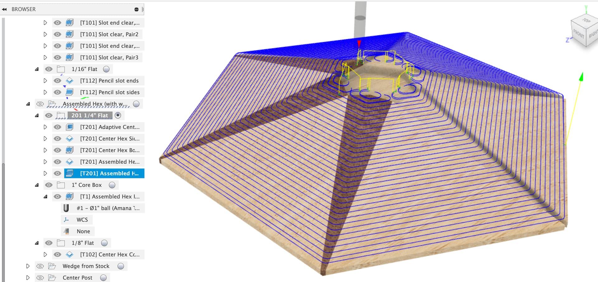
Looks like my center hex pocket side clean-up is cutting deeper than the bottom clean-up:
And looks like that’s what the toolpath is, in Fusion:
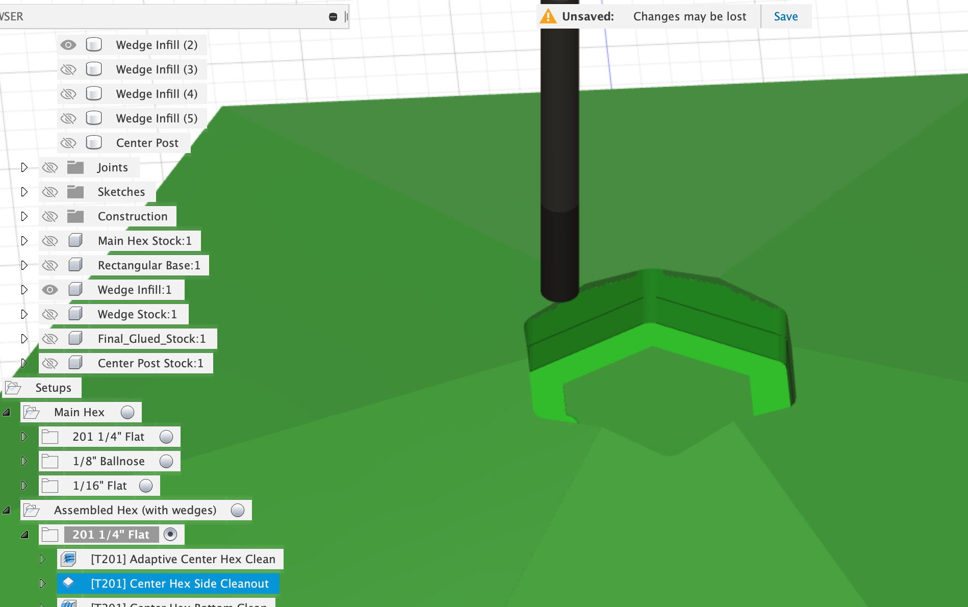
EDIT: Ah, I think that’s because there’s another bottom clean-up pass coming and the first was an adaptive clear that left some stock behind on purpose.
1 Like
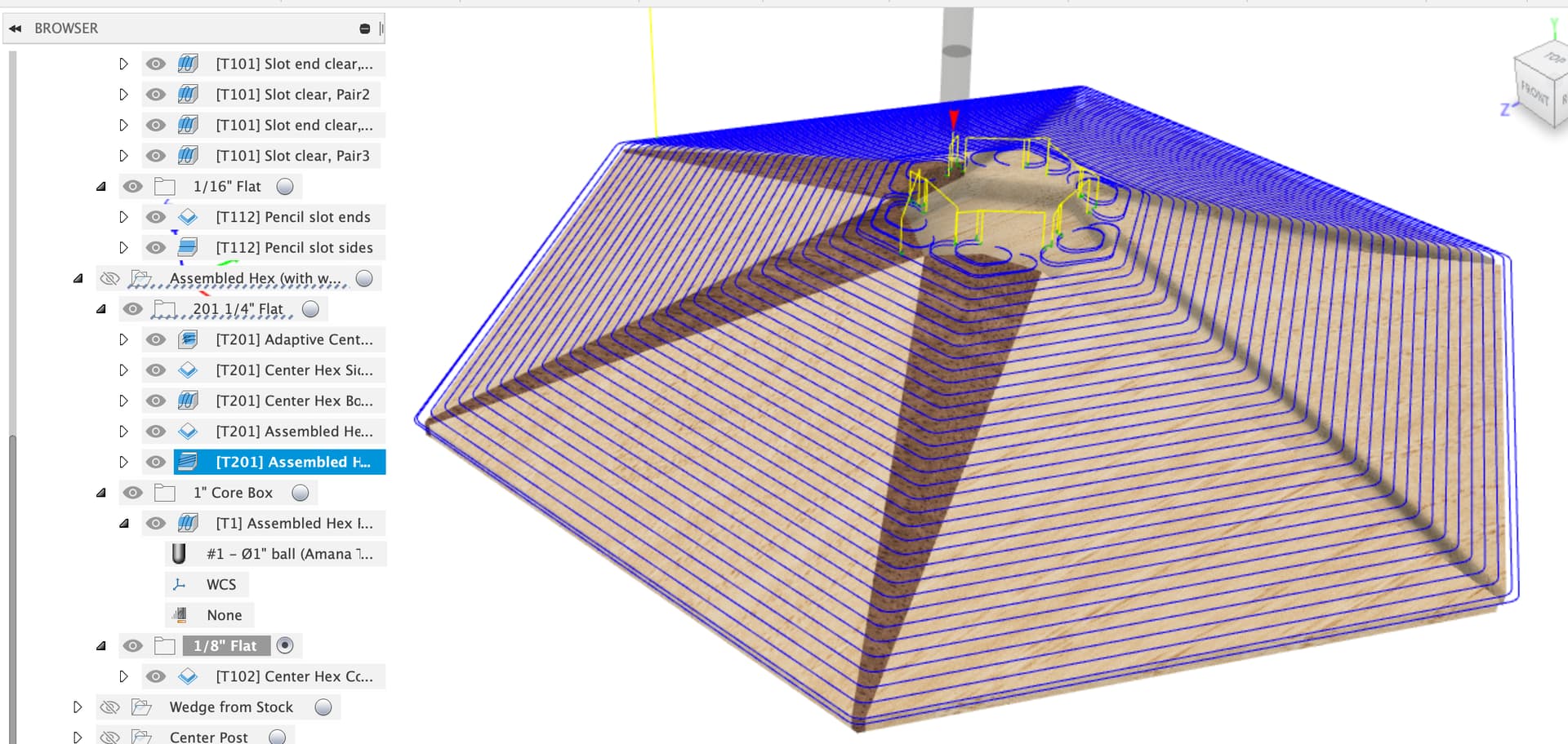
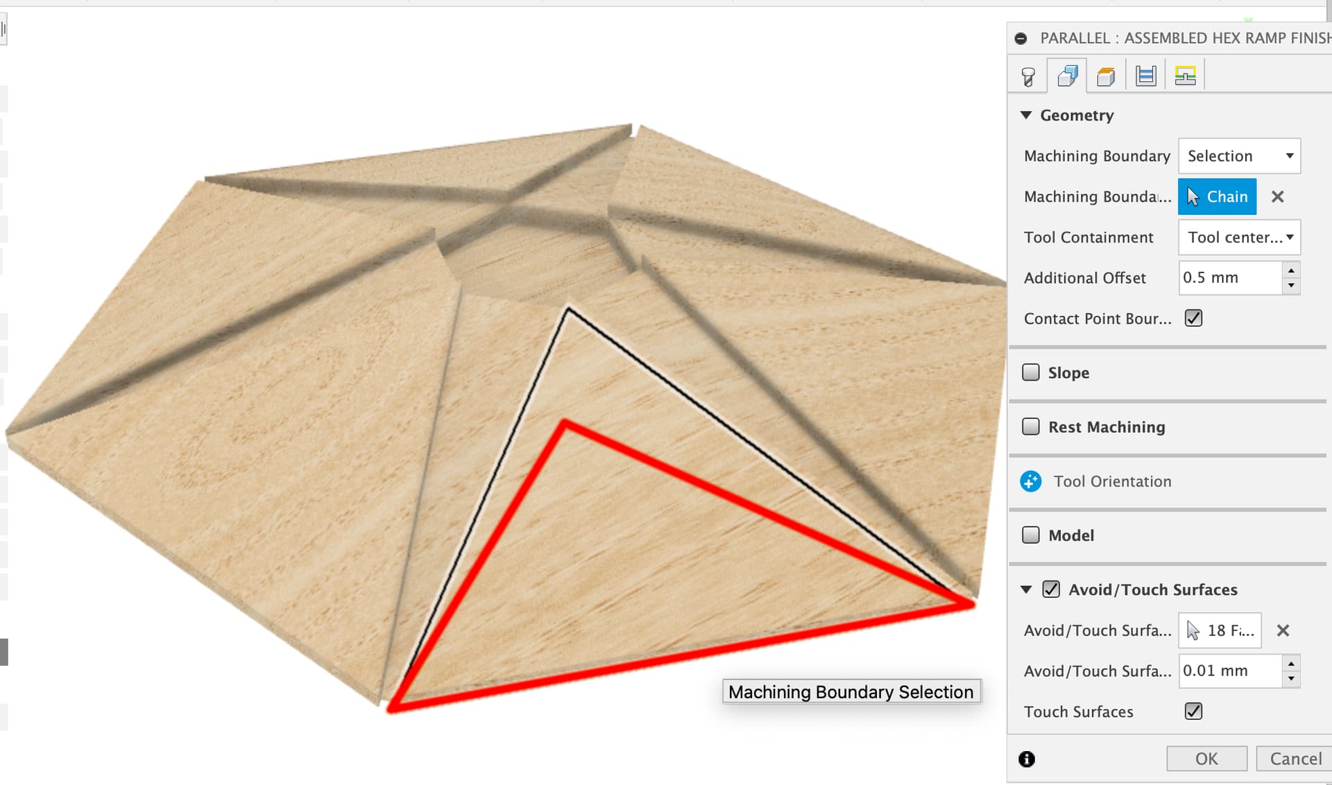
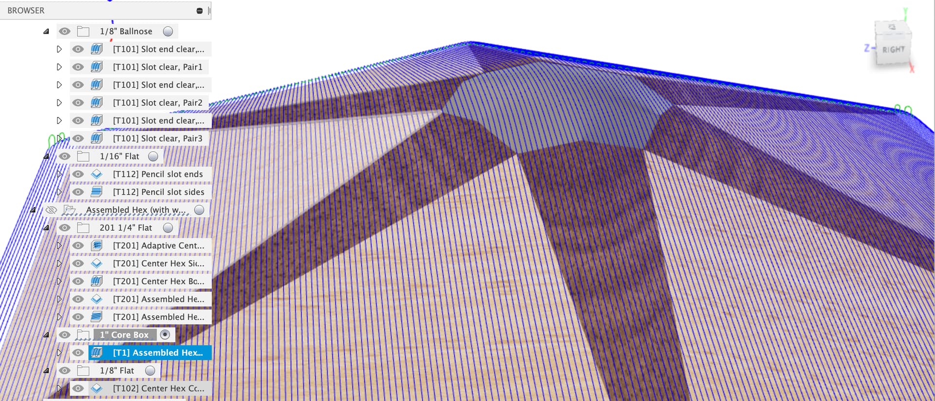
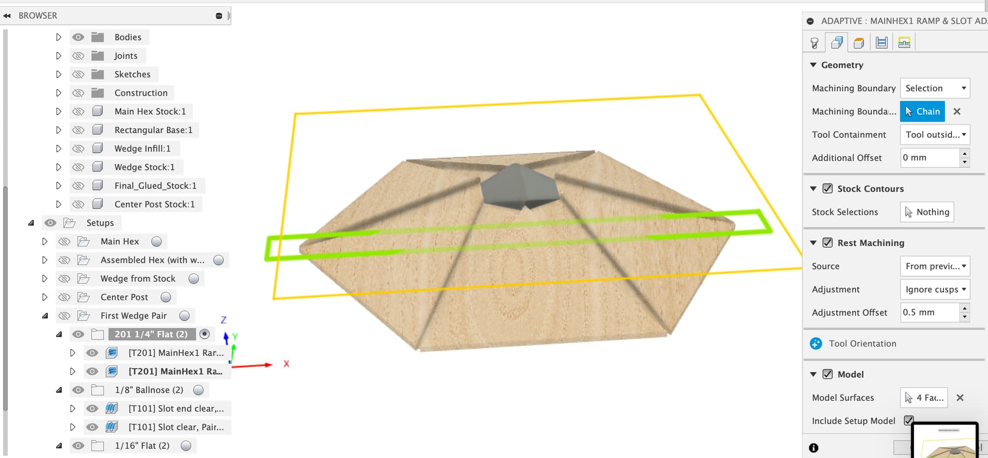
The final ramp clean-up with the 1" Core Box bit is dipping into the center hex pocket and cutting the bottom there as well, which is kind of silly. I took a look at the dialog and don’t know what to select to avoid cutting into the center hex area with the bit:
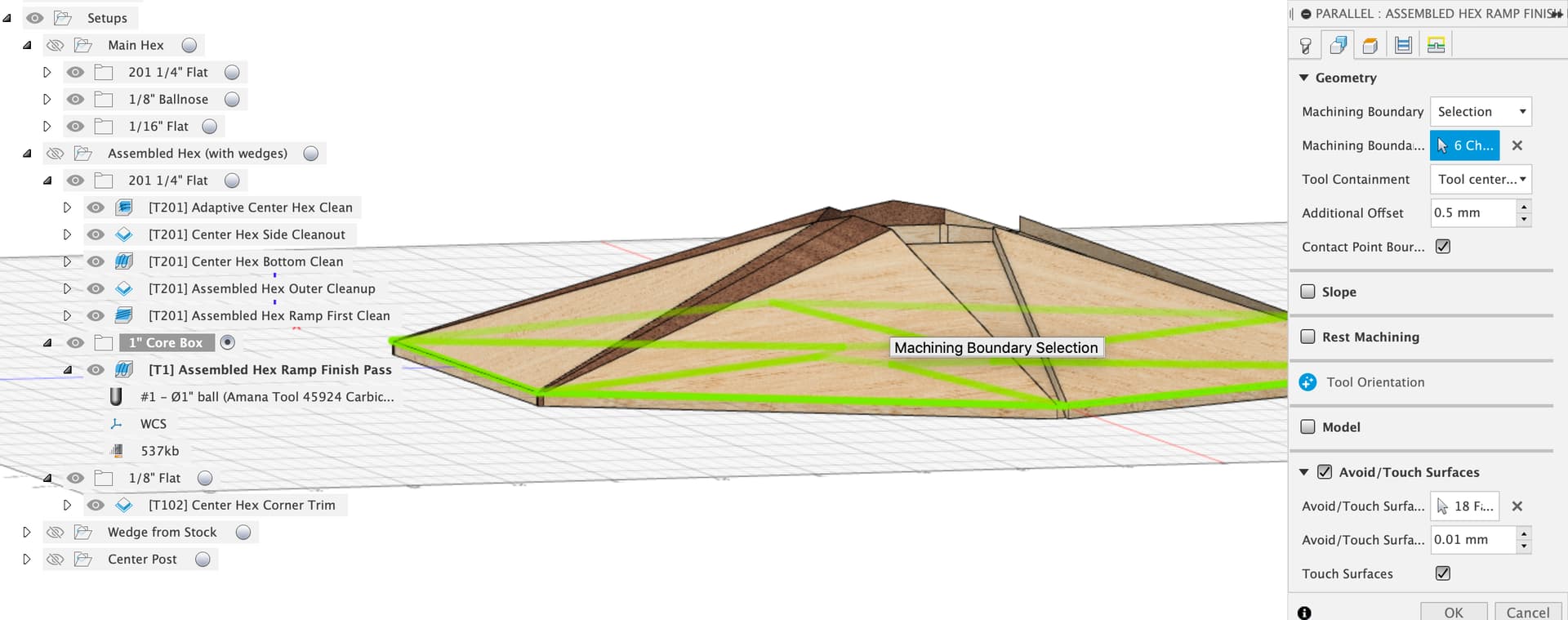
I couldn’t make out what green selection boundary actually is.
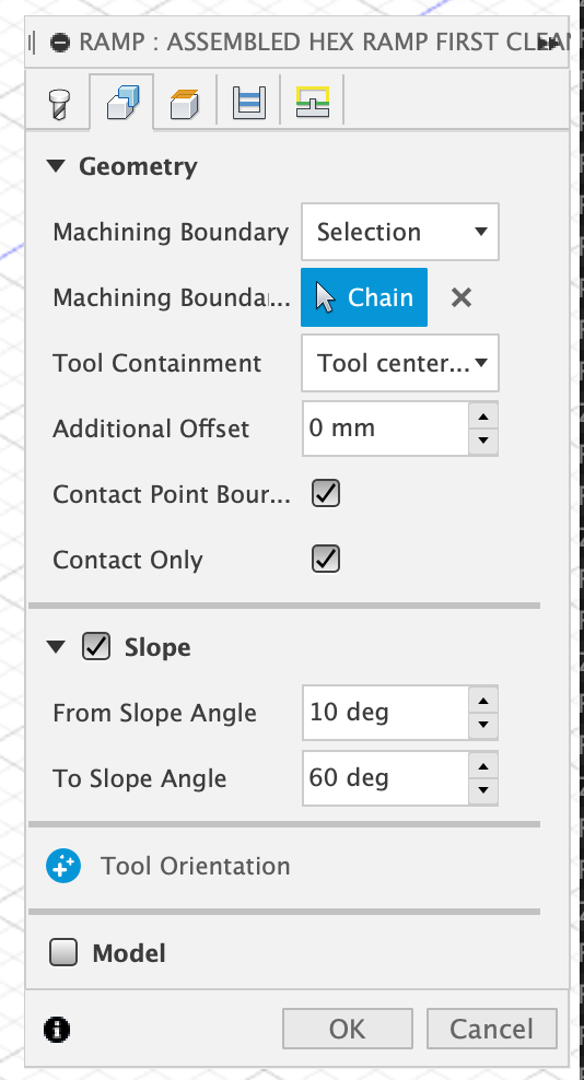
Also, for the prior ramp pass using the ¼" end mill, shouldn’t I check both Contact Point Boundary as well as Contact Only?
Or does that not matter since I’m hitting it with the Core Box afterwards?
Thanks.
Here’s my latest, in case @LiamN , you’re willing to dive in again.
LargeNewell v24.f3d.zip (2.0 MB)
woopsie, so they actually were loose. Don’t hate me, I forgot to explicitly mention that you should also make sure that one of the setscrews is aligned to the flat on the motor shaft. Hopefully you did / it is, and if it isn’t, you’ll know soon enough…
The wiring situation is more of a (potential) concern, maybe reach out to support for advice.
1 Like
Yep, what he said, also a drop of blue loctite threadlock on the grub screws goes a long way.
Looks like you’re making pretty good progress in getting a full test part put together and cut now.
I’ll take a look at the Fusion model later on today, on the ramp pass & contact point only, not sure, but as you say, it’s not the finishing pass anyway. To keep the final pass with the rounded box bit out of the center hex, we might need to put a bit of extra geometry in…
No, they weren’t loose, I just extra-tightened them, luckily without stripping anything.
At this point I’m going with an electrical/wiring issue. Seeing the issues with the carriage X-Axis behaving badly on INIT could produce that stock chart on the product.
While many things about the Shapeoko Pro are impressive, how the wires are attached to their connectors are not. I had a bad Z-limit wire out of the box, and when I got sent a new one I was instructed NOT to feed it through the drag chain but to open each link and lay it in, due to the fragility of the wire end to connector interface.
1 Like
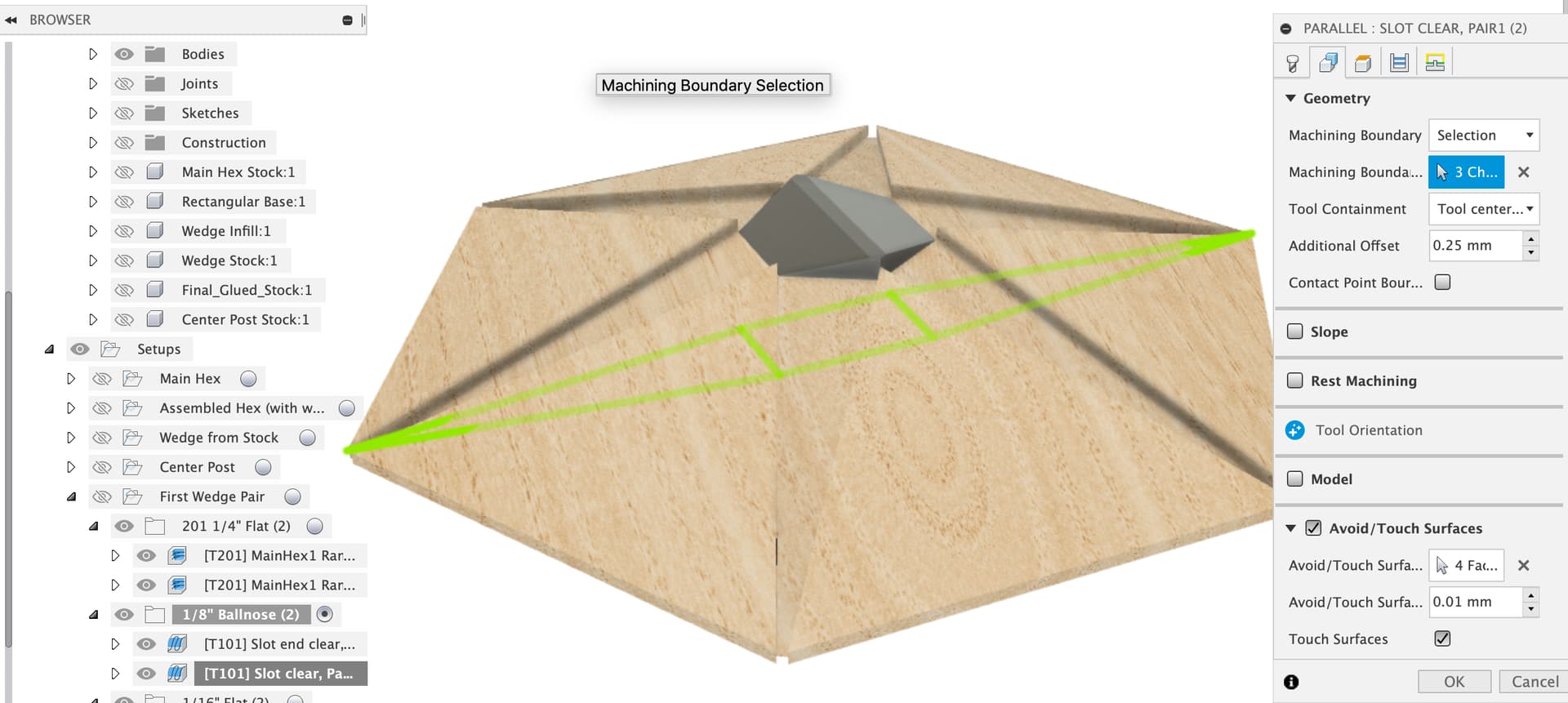
Good question, I turned contact point boundary off and on again and looking at the blue toolpaths, the contact point boundary lets the ramp pass walk right down to the edge of the hex, probably giving a better prep for the finishing pass.
Aha, the dark arts of boundary selection in Fusion CAM, Professor Snape teaches that class.
Here’s some info from Autodesk
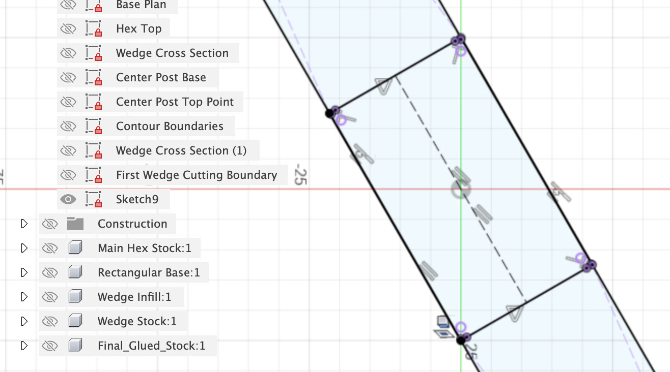
It’s a lots of clicking thing but first click on the boundary of the upper hex face like this
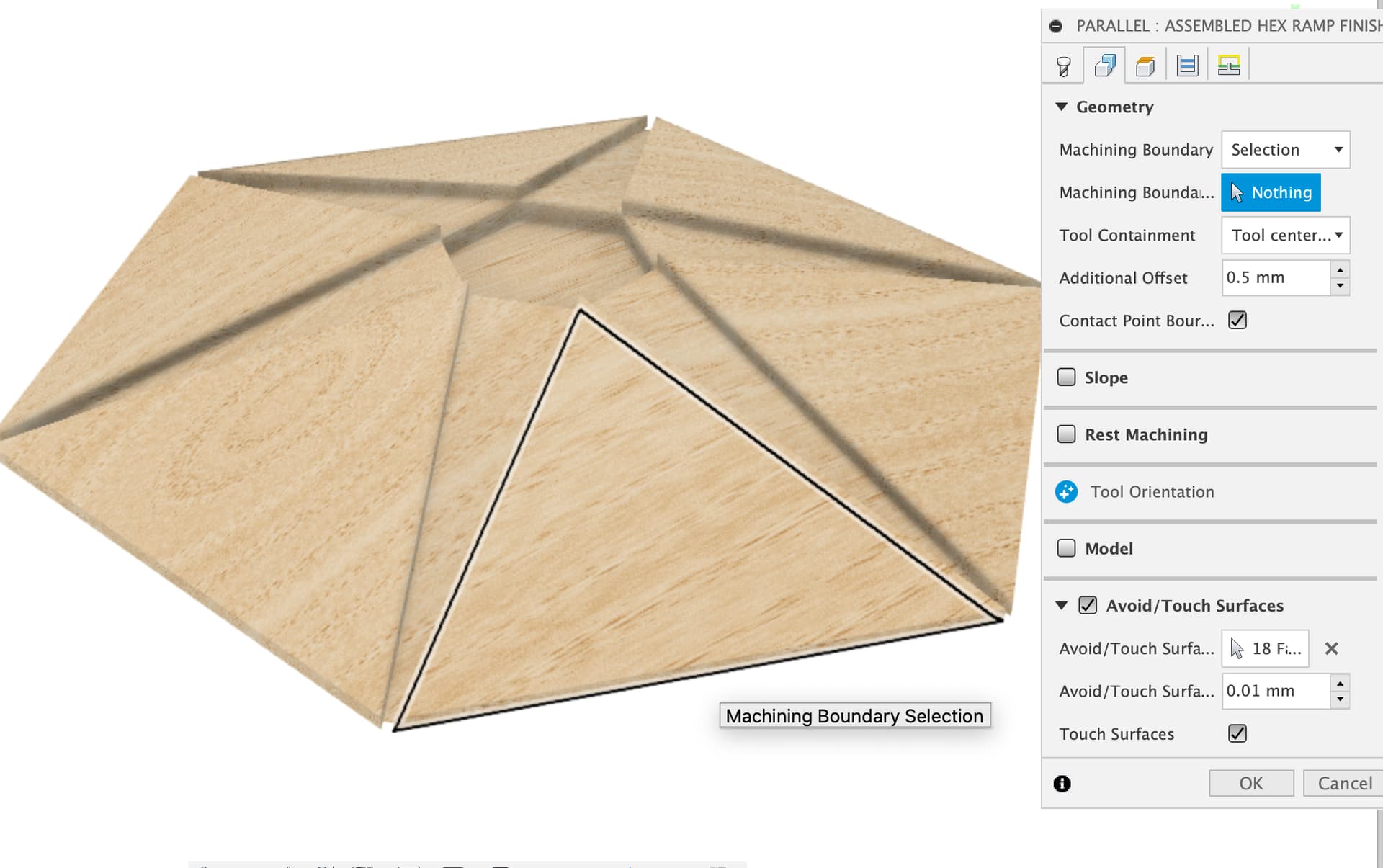
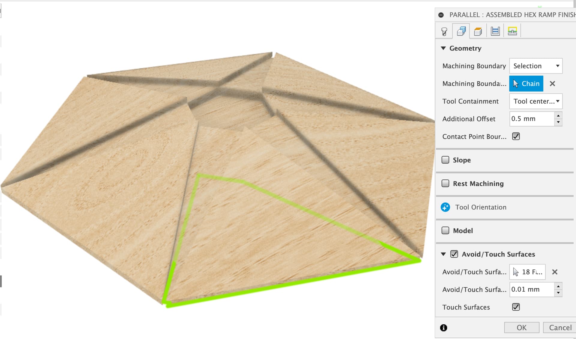
Which results in the boundary being projected down onto the Z plane of the CAM setup, the green outline here.
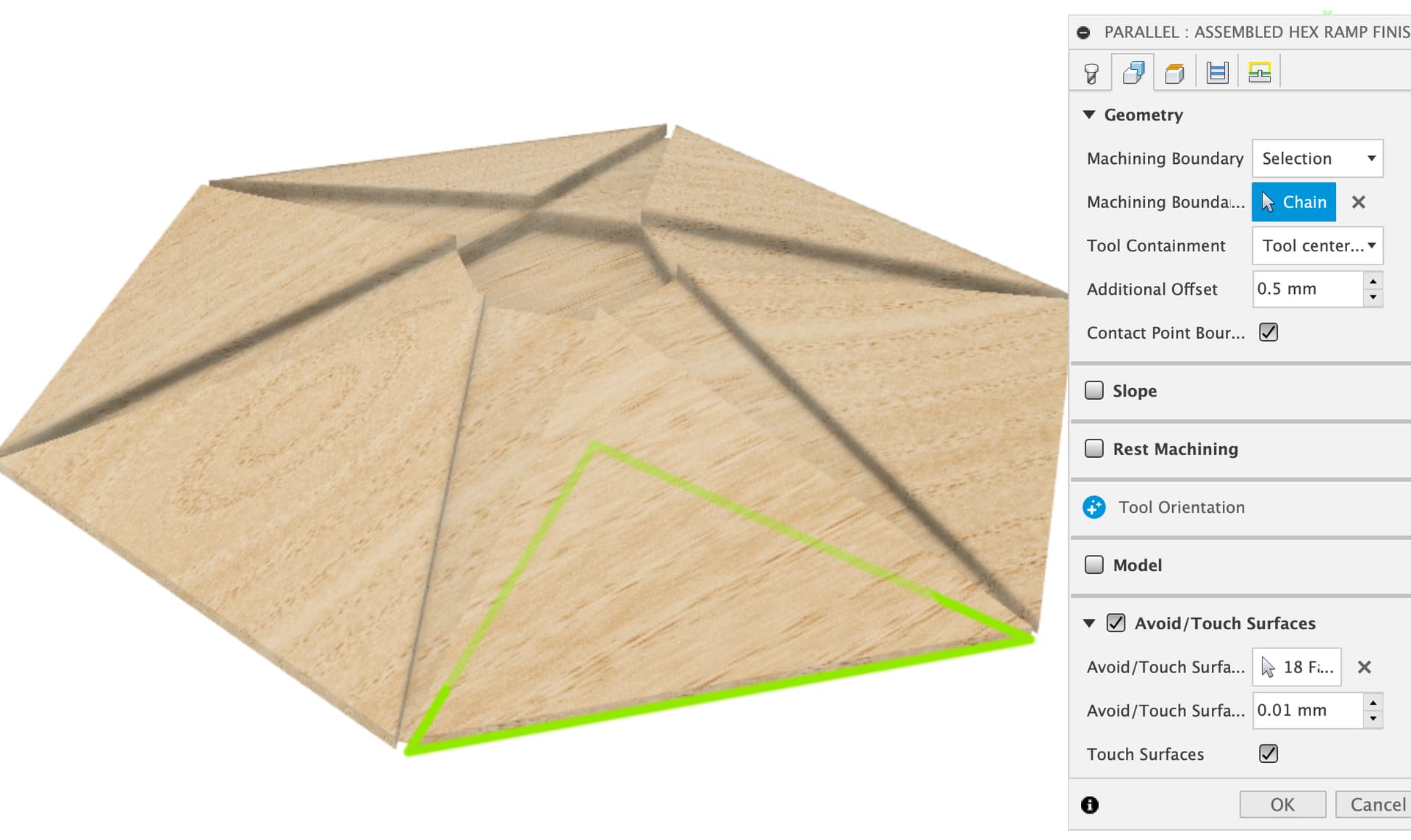
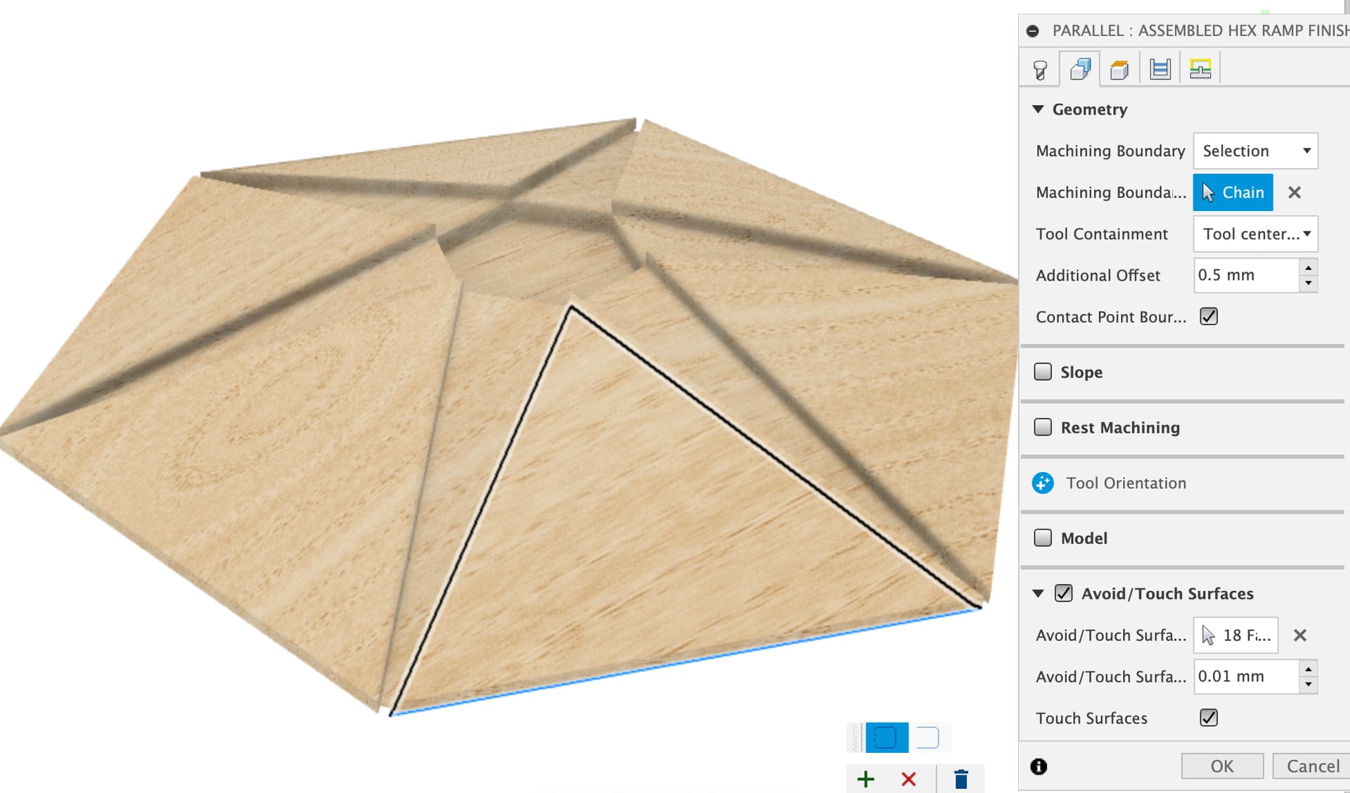
We can edit this some more though, which is useful to avoid having to draw sketches of containment boundaries for toolpaths and took me ages to realise how people were doing it.
Hover over the green boundary and it goes red
Click on it and you get into editing mode where you can make the boundary closed or open, and change what’s included
I’ve now selected the edge of the next triangular face over to include the adjacent wedge in the boundary
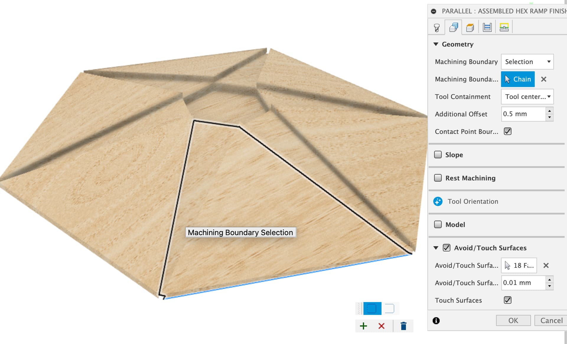
Click on the + to accept the contour change and we get the funny shaped green outlines that, with 6 of them, built up the containment boundary for the toolpath.
OK, now I should admit that I saw that when I set up the toolpath but left out fixing it as things were getting complicated already, so blame me for that one ![]()
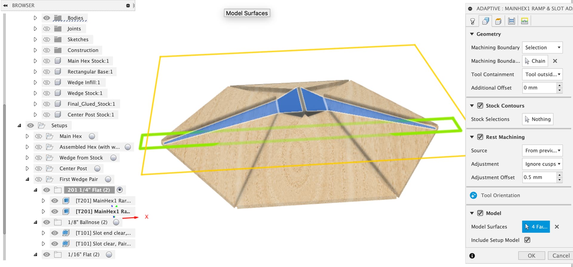
We have a bit of a mess of both containment boundaries and touch surface in use here, let’s dump the containment boundary and just specify surfaces.
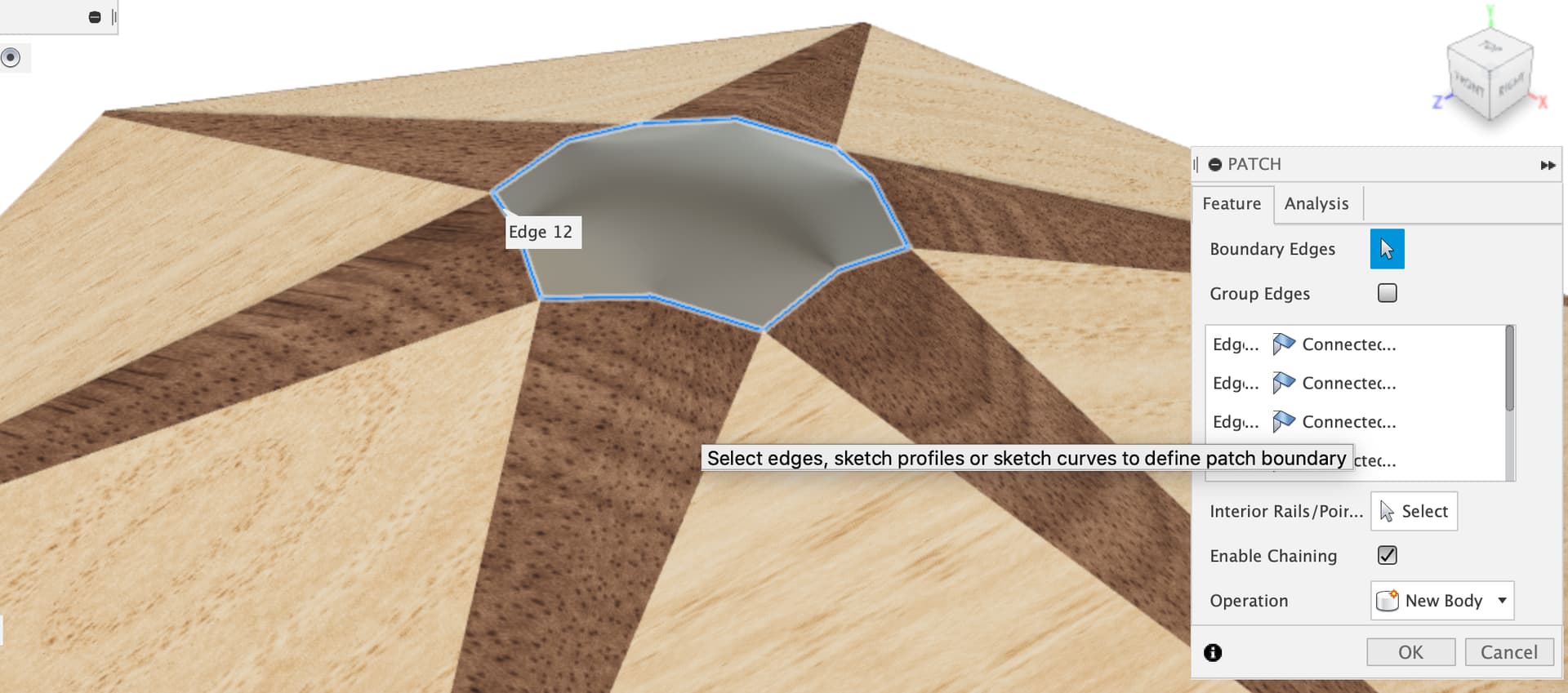
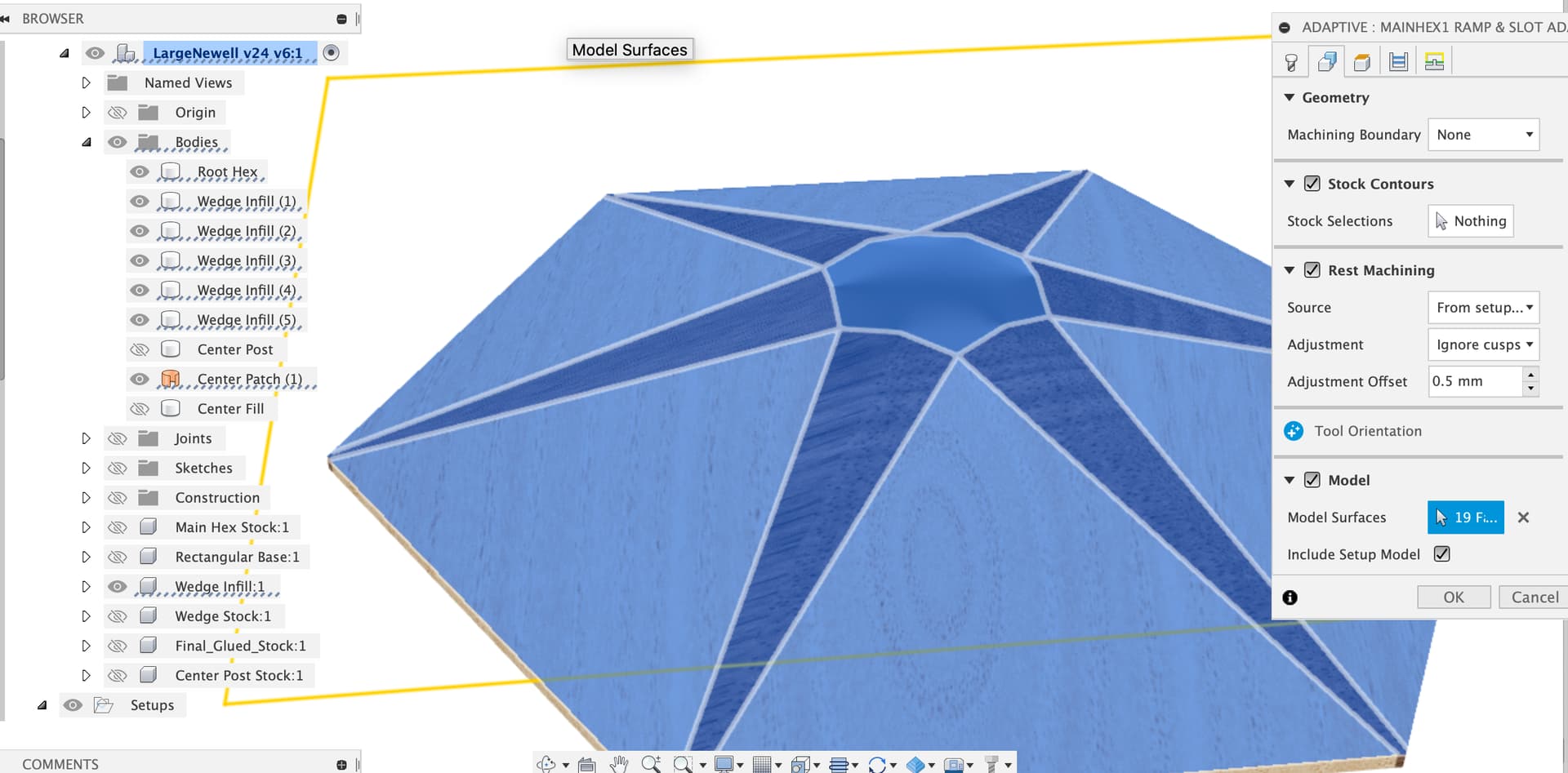
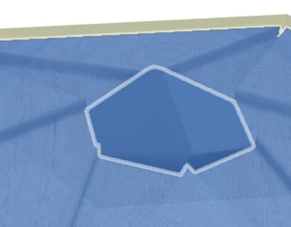
If we want Fusion to stay out of the hole, the best thing to do is to put a lid on the hole, back in Design tab, go to “Surface” mode and Create Patch
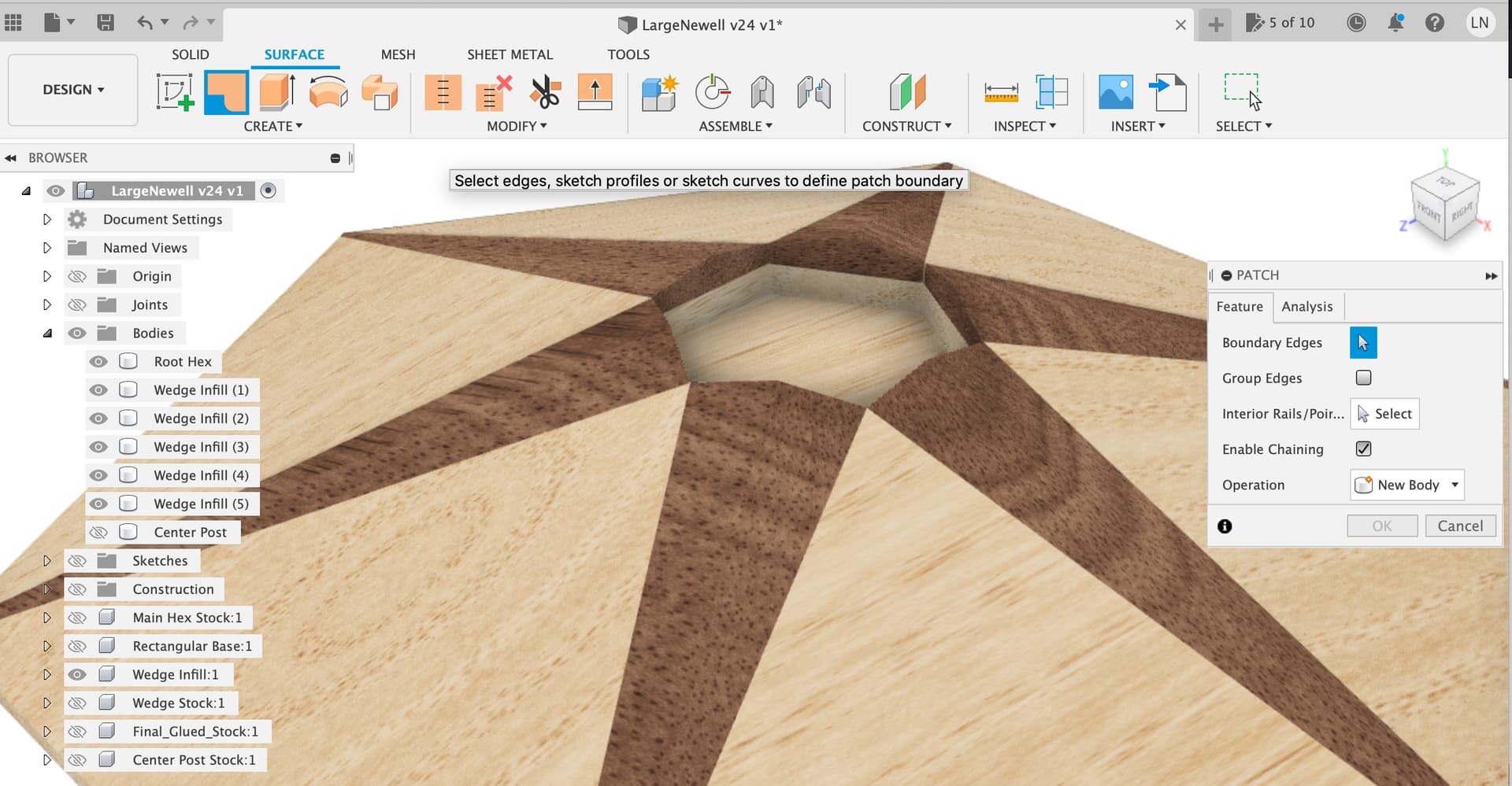
Select the inner top edges of the 6 wedges so that there’s a full perimeter for a patch surface
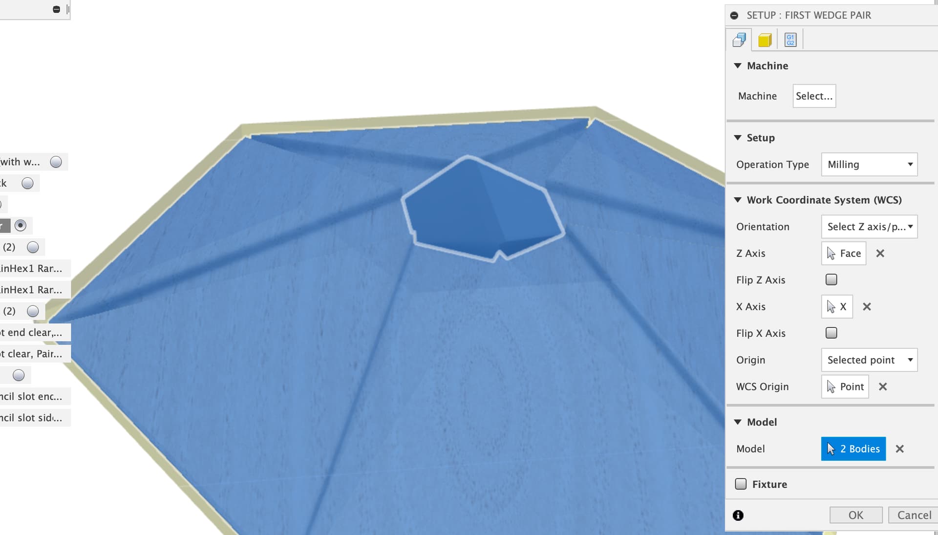
And back into CAM, clear the machining boundary selections so we just have surfaces to touch
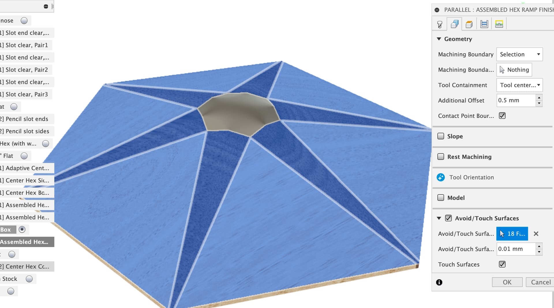
then add the new center patch to surfaces to touch
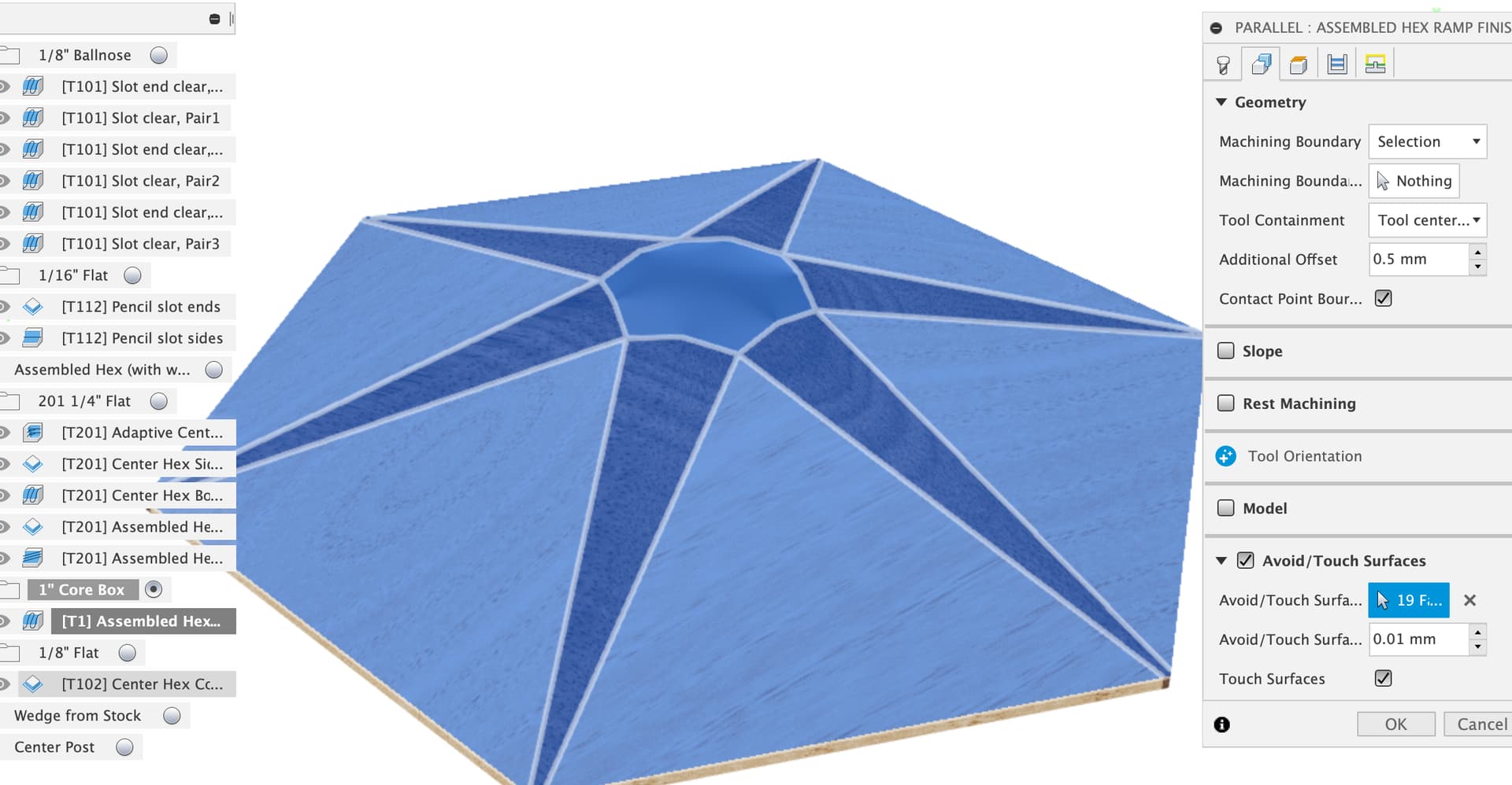
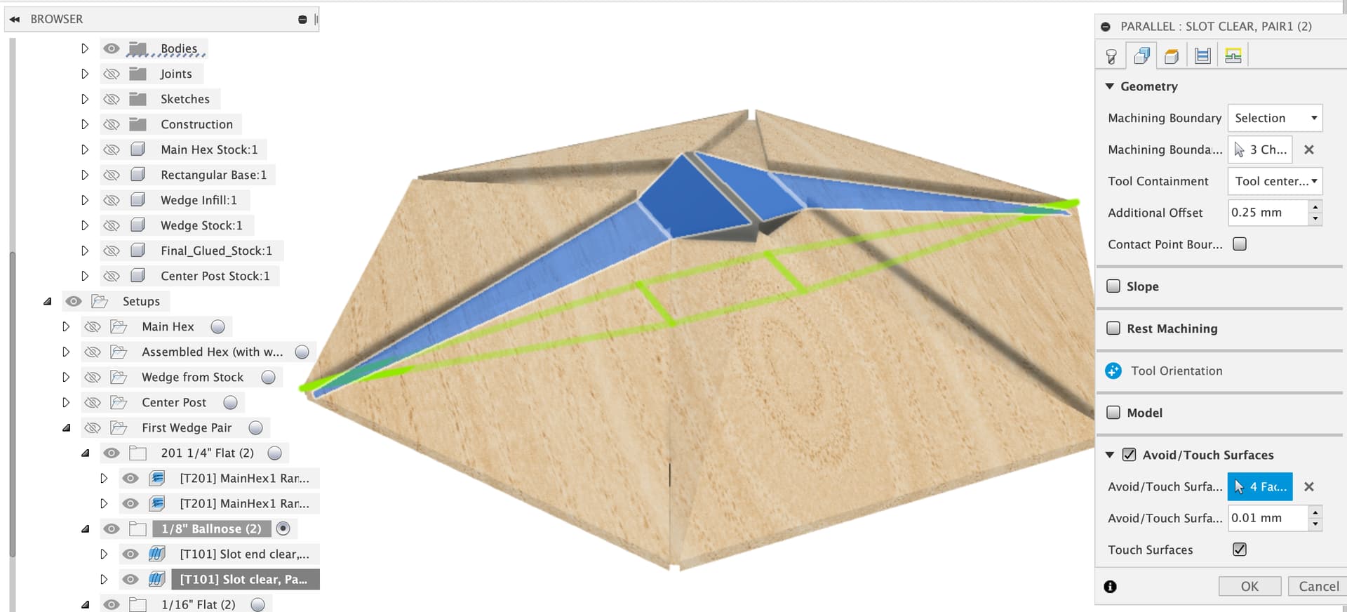
And now the toolpaths do what we want and just float over the center post hole
There might be an easier way but I understand how this one works and it makes “sense” to me that if I put a new surface in the toolpath will follow it.
Does that help?
LargeNewell v24 v2.f3d.zip (2.4 MB)
1 Like
Thanks yet again.
The Center Hex Corner Trim with the T102 bit was an empty toolpath, but after editing all the toolpaths to have lower retract and clearance heights and some other minor changes, it generated and previewed fine.
Here’s the file as I’m going to cut tomorrow AM in another test blank:
LargeNewell v25.f3d.zip (2.9 MB)
I lowered the heights because on the previous test the carriage hit the Z-limit switch, which didn’t seem like a good thing. Since the first two toolpaths take the stock from STOCK_HEIGHT to MODEL_HEIGHT plus a mm, I set changed the heights to be relative to that instead and tightened some of the up a bit. I believe I’ll clear everything with a few mm to spare.
I also reduced the thickness of the base from 18mm to 13mm to gain me another 5mm as well. I’ll run that MDF through my big drum sander to thin it out. Although, I suppose I could surface it to thickness on the Shapeoko itself, which would guarantee a base surface that’s flat and parallel. Hmm, maybe I should do that first tomorrow morning. I’ll also use the Shapeoko to mark the center hole in the base, which should be better than aligning the stock to a line on the base.
1 Like
That is definitely a good plan, hitting the Z homing switch is not a good thing, these don’t act as a limit switch on the Shapeoko so if the axis hits the endstop the motor loses steps and the machine loses zero in that axis. You have to reinitialise the machine after this.
Overcame my X-Axis wiring problem temporarily (zip-ties to hold the wire connection just so) and completed a hex in scrap! But, not without some issues, only one of which didn’t “sand out.”
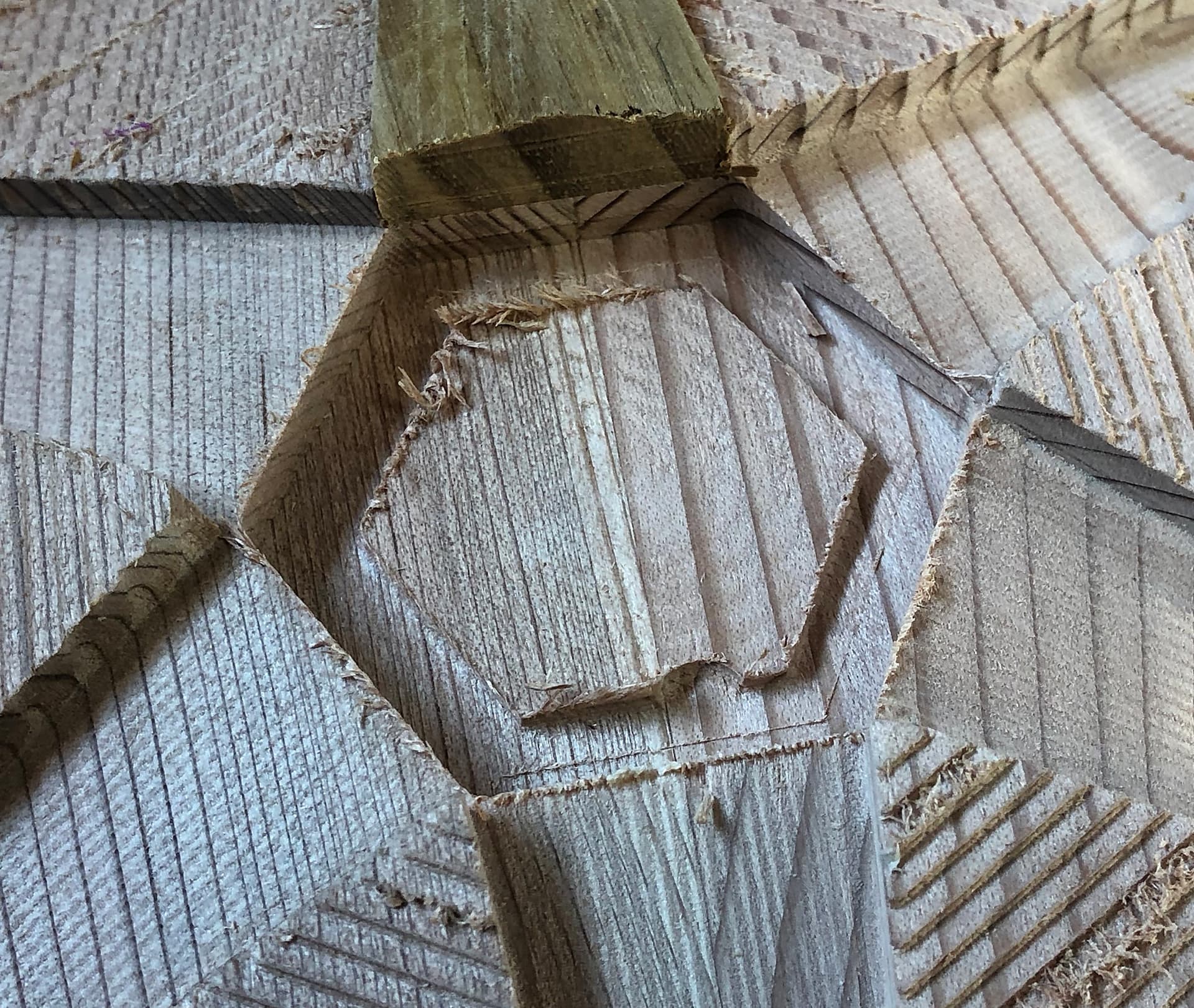
And that’s the divet/shearing of the hex stock at the point near the center opening:
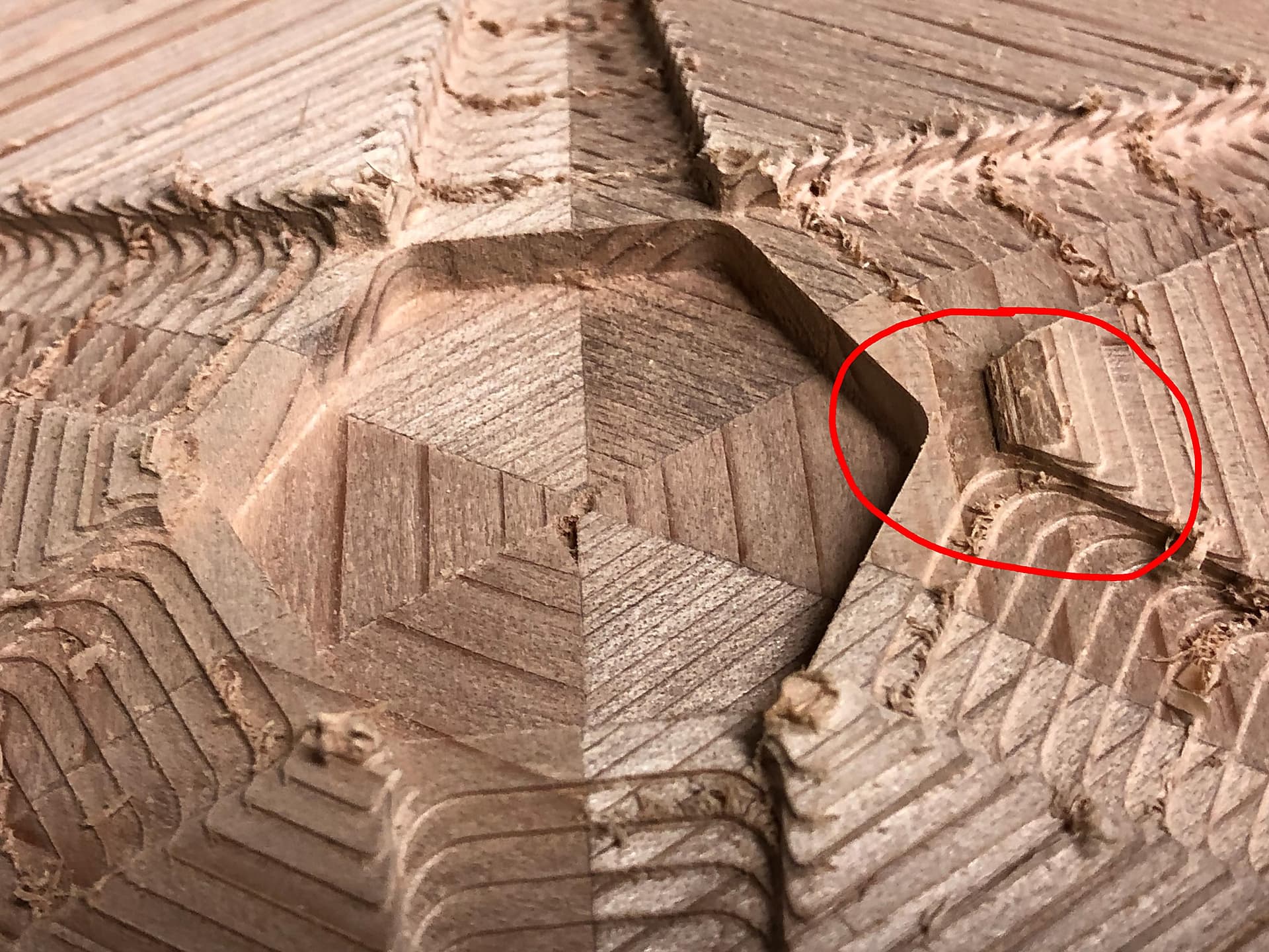
Now this is redwood, which is better than MDF and maybe not as good as the Narra hardwood I’m going to use, but it is a concern. I’m wondering if maybe I should cut the wedge pockets first, and then mill the outside surface ramps. All using the ¼" end mill, so reaching in isn’t a problem. The only other things I can think of are to speed up the router, slow the feed, and reduce the DOC. Thoughts?
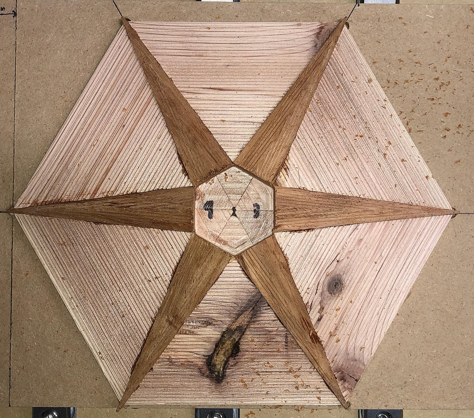
Here’s what she looked like after the first ¼" end mill pass (2 tool paths) and cutting the center hex pocket with ¼" and ⅛" end mills:

Next up was gluing in half the wedges. Just need a little bit of light sanding cleanup in the tight spots of the wedge pockets. Tiny bit, actually. But, after gluing the wedges in I have to re-run the center hex pocket cuts to trim the wedges so that the rest of the wedges can fit. And I got splintering:
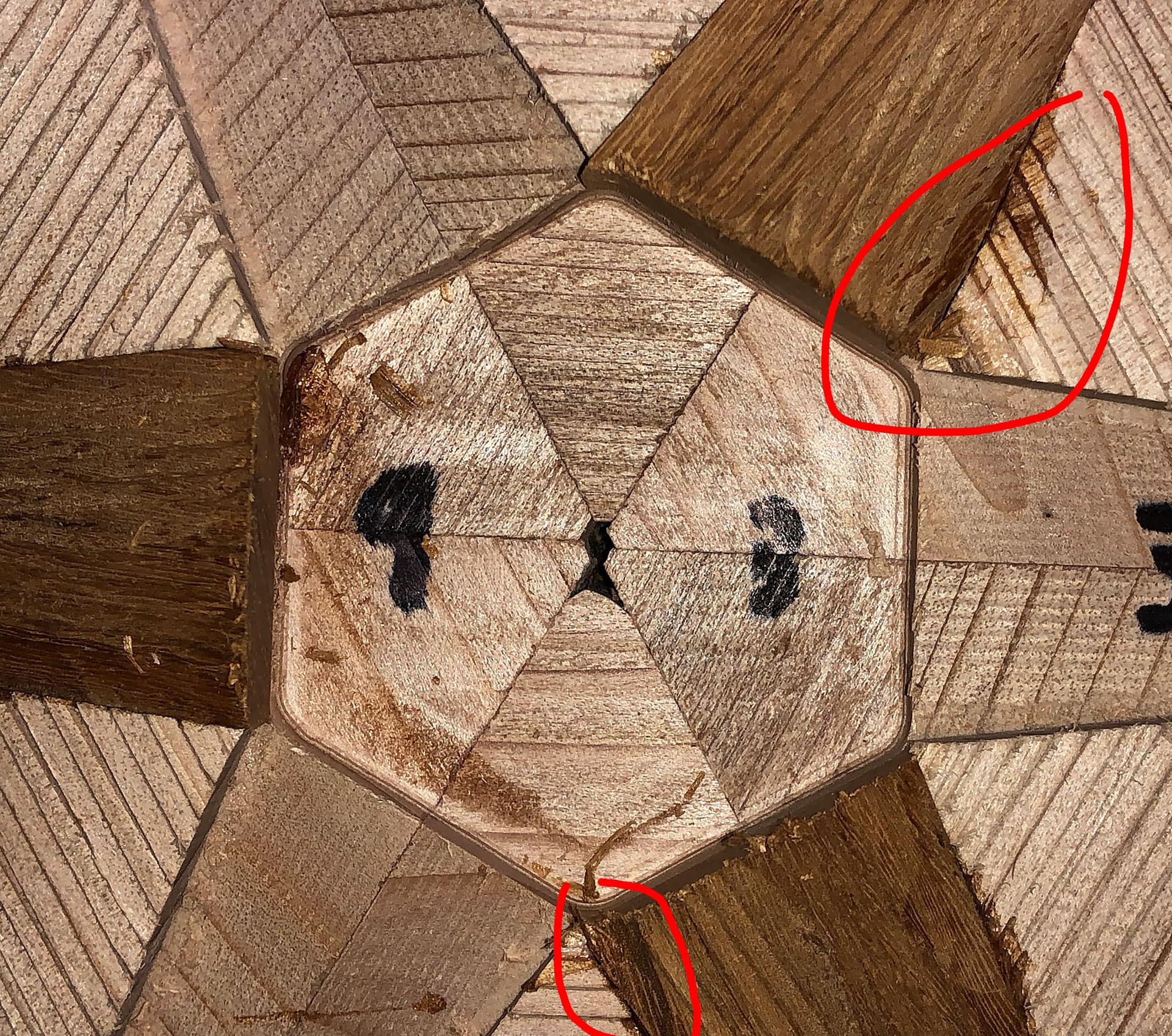
Here’s another angle:
Now, I thought this might actually be OK, as the splintering didn’t go below the hex surface. And, I was mostly right. I’m wondering if I should not just run the bottom and side passes, but also the earlier adaptive contour pass? Again, DOC/rpm/feed speed are probably the issue here. These wedges are Narra, which is what the body of the hex will eventually be, with the final wedges ebony. I think ebony might splinter just as easily.
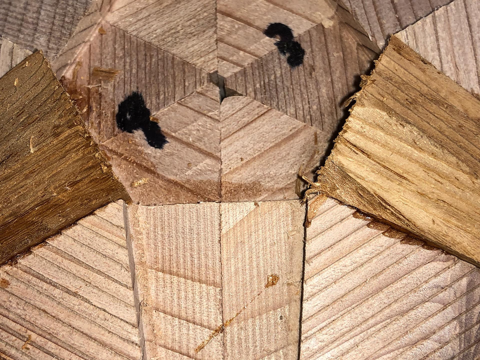
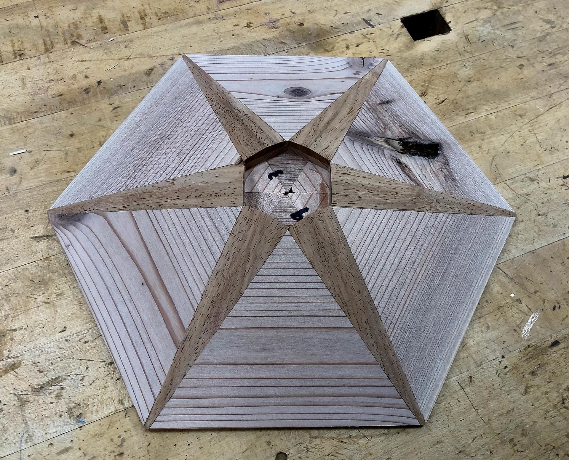
Then, here’s with all 6 wedges glued in and trimmed:

If you look carefully at the outside points, you’ll notice that the wedges aren’t perfectly centered. I believe that’s due to me removing the hex from the base to glue the wedges in, then reattaching it and being slightly off. My plan for the real deal is to drill holes in the sacrificial base so that the wedges can protrude below, and that’ll let me glue the wedges in without removing them from the base and without removing the base from the spoilboard. Which should fix that problem (but, more later).
And then there’s a ¼" end mill face clean up to get the wedges level with the main body and then the 1" Core Box bit to get a smoother surface. I forgot to get a picture of the Core Box surface. It’s pretty decent, although the toolpath just runs horizontal, so where the grain happens to line up it works better, but I don’t think I’m going to bother to change that as it all has to be sanded out anyway.
It was already late and I was tired, but I did a quick sanding job. Here’s what she looks like:
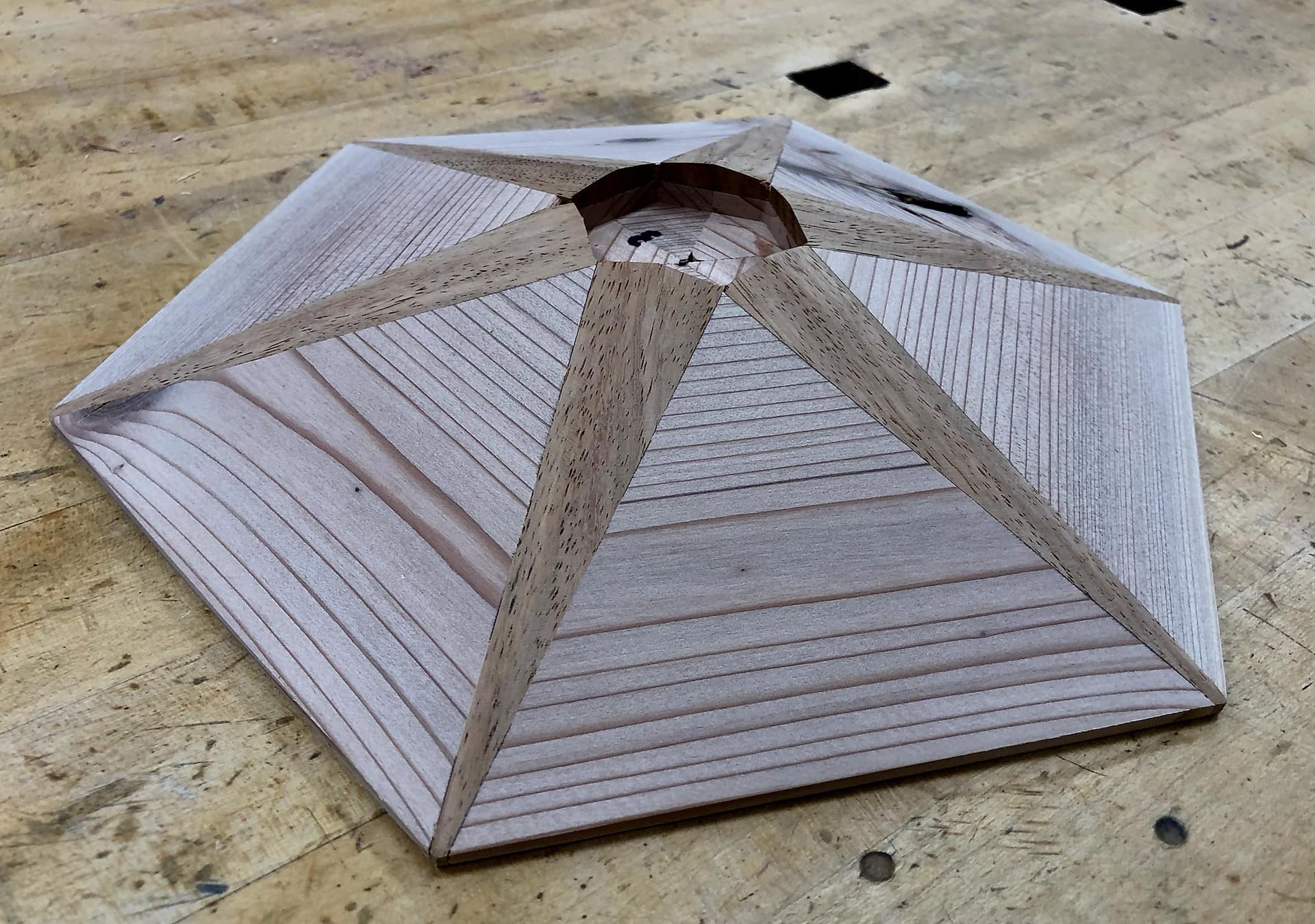
You’ll note that the outside points look pretty good now. That’s because I sanded the outside edges on my disk sander to make them line up better. I had enough extra width in the finished piece to do this and still make size - if anything it helped the size fit the irregular post better!
Anyway, a good day in the shop after a frustrating couple of hours debugging the Shapeoko wiring. I’ve now had 3 wires go bad in about a month. The divet thing worries me the most as that would be hard to fix with Famowood. The ebony, being so black with hard to see grain, is actually easy to patch up should that be needed, but the Narra body would be noticeable. Going to sleep on it.
@LiamN, thanks again for all your help. No way I could have gotten this far this quickly (even though it doesn’t seem like it was quick I’ve learned a ton along the way).
PS: My wife looked at the piece this morning and said I could have made a couple of “real ones” using my normal techniques by now. Sigh.
8 Likes
Well that’s good progress.
Using your normal techniques what would your work order be to avoid that tear out in the top corners of the hex faces?
The wood is clearly weak there as it’s cross grain and whilst running lower depth or width of cut will help, I’m not sure it will do enough. Not milling out the center hole until the end probably won’t stop the tear out of the hex tips as they will still come to the same point anyway.
It might be worth trying cutting one opposing slot pair at a time and glue in the wedge before doing the next slot pair so that the corners are not left completely unsupported We can set up toolpaths for this easily enough, leaving the hex hole for the center post uncut for support.
I wish I had done a video of the last piece being cut without Sweepy so we could see exactly when the piece breaks off. But, some analysis might help.
I’m going to assume that since we’re climb cutting, we’re actually OK on cutting the slots the way it’s setup now in the first toolpath, and that it’s when we go to mill out the center hex pocket that it sometimes breaks off.
From Fusion’s simulation, here’s the first approach to the sharp corner:

And here’s the bit leaving the corner:

And here’s a later snap so you can see the other corners:
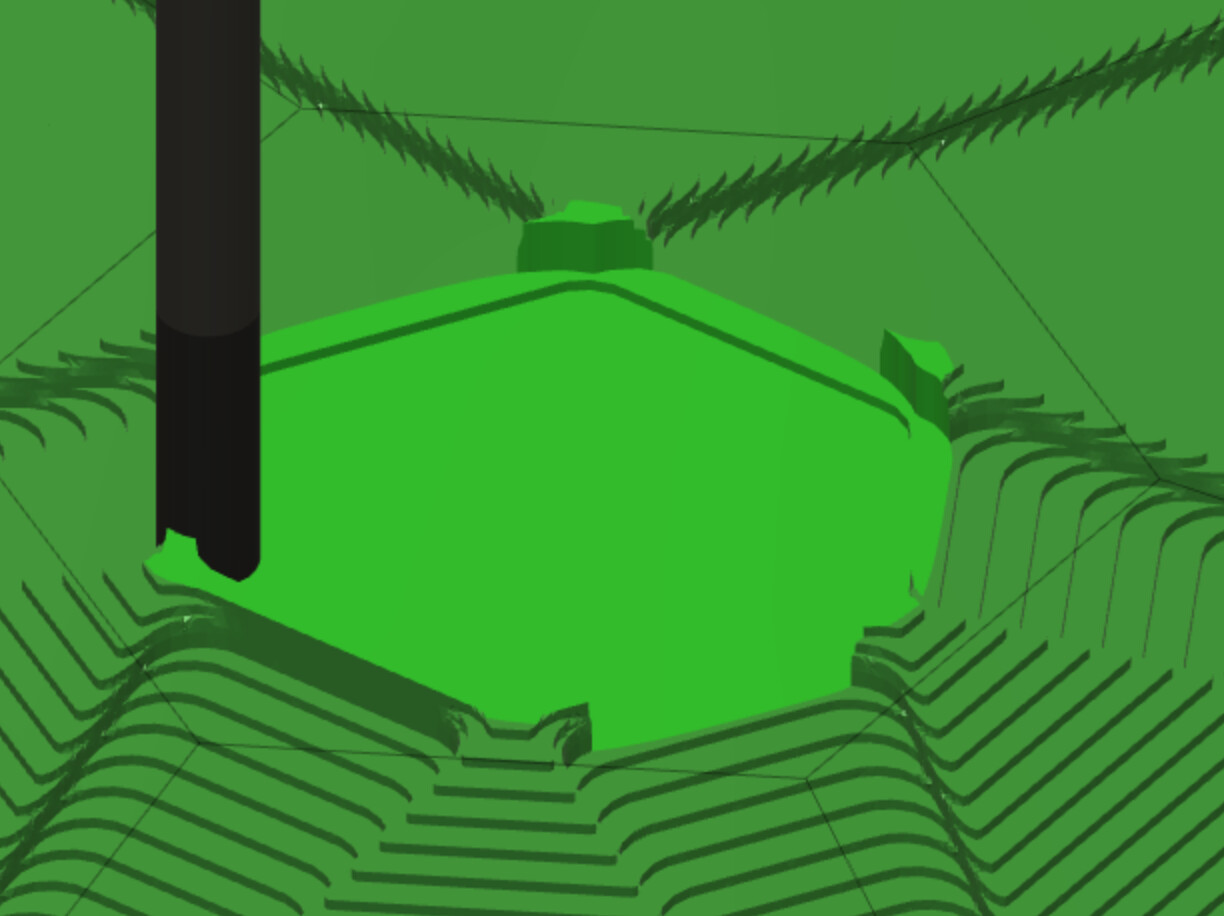
And, finally, here’s my guess as to the bit position just before the break-off:

The bit is rotating clockwise viewed from above, so with climb cutting the bit is moving from screen left to right here. The edge of the bit wants to grab that corner and push it into the open slot at the left.
So, your idea of gluing in a wedge would help support the corner, but I can’t get the wedge in until the center pocket is milled anyway, so I don’t know how that’s practical. Maybe I’m overlooking something?
What I’m seeing is that the sharp corner where the two wedge pockets meet isn’t cut until the center hex pocket is cut. Shown here:

My normal style would be to fully cut the wedge pockets and then cut the center hex. I know we’re kind of doing that today, but there’s no “follow-through” on the wedge pocket cuts, meaning we don’t cut the wedge pockets such that the bit keeps traveling into the center hex pocket.
So, my idea here is to change the Machining Boundary to enable the full wedge pockets to be cut on the first toolpath, allowing the bit to travel into the hex pocket as needed. Then the hex pocket adaptive clear is for the rest. That’s not happening today, even though the Machining Boundary is set to None:
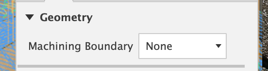
So I don’t know how to accomplish this.
One other thought is around which side of the wedge pockets to cut first. I’m thinking we may want to cut all the left sides of the wedge pockets and then cut all the right sides of the wedge pockets. Cutting the left side with climb cutting is trying to throw the corner into the open hex pocket and so having support from not cutting the center hex pocket as well as additional support from the right side of the adjacent wedge pocket not being cut yet will help. Cutting the right side of the wedge pocket should be fine with climb cutting as that’s pushing the stock towards the wider part of the ramp.
Maybe these two changes, plus using a stronger wood than redwood would be enough.
Did I at least explain this? It’s pretty esoteric.
Sorry for the delay, back now, had a think about it.
I agree that not machining out the center hole first in the adaptive clear may help, that’s easy enough, make a body which fills that gap and include it in the model for that setup, or just that adaptive clearing toolpath.
Also, as you say, running a less aggressive depth or width of cut is likely to reduce the mechanical stress on the workpiece, that’s definitely worth a try.
I might try to do the wedges a pair at a time to eliminate the sharp corner problem, the grain direction of the wood is always going to make those parts very weak, no matter what we do.
The tricks in the option below should be applicable to other variations of selectively clearing and cutting you want to try too.
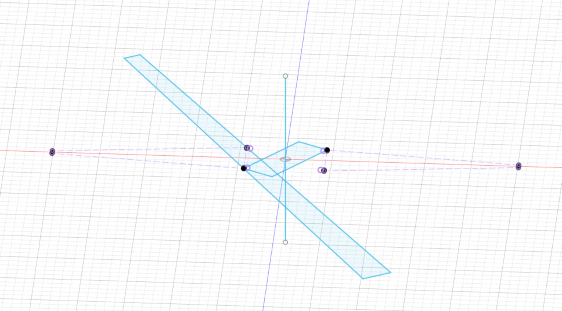
Taking the first wedge pair, I added a body in the middle to plug up the hole, but sliced it off using the plane of the wedge pockets. I also created a sketch to use as boundaries for toolpaths.
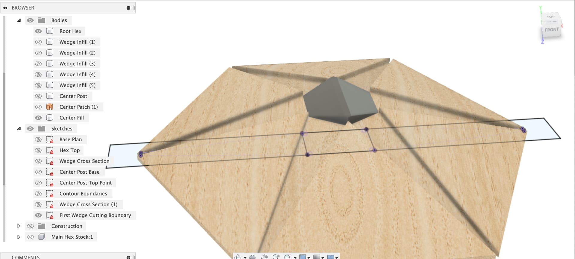
I copied the Main Hex setup, the only change is I included the new center plug as a body.
The first adaptive clear selects faces on the hex, wedges and the surface we patched over the center hole.
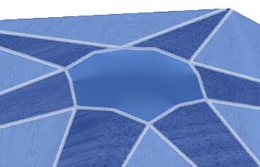
Which gives us an all round adaptive clear which doesn’t go into any of the slots
Next up, clear out one pair of wedge slots, I copied the adaptive clear job and selected the new sketch as a boundary
And also selected the four faces we care about
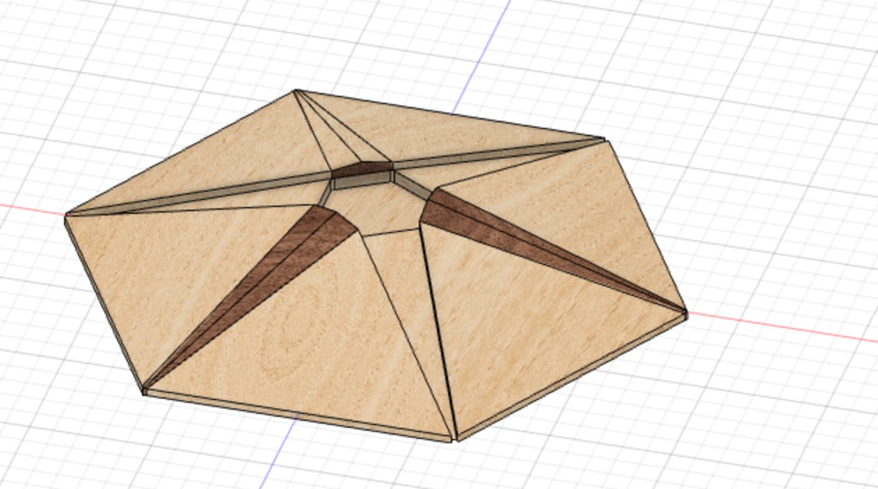
Which gets us a roughed out hex with two opposed roughed out slots with their ramps continued across the center hole.

Then I kept just the two ballnose toolpaths that do these slots, I used the updated boundary sketch to let them cross the center hole
And selected the faces of our temporary plug to let the ramps continue, this gives an enlarged surface for gluing down the wedge
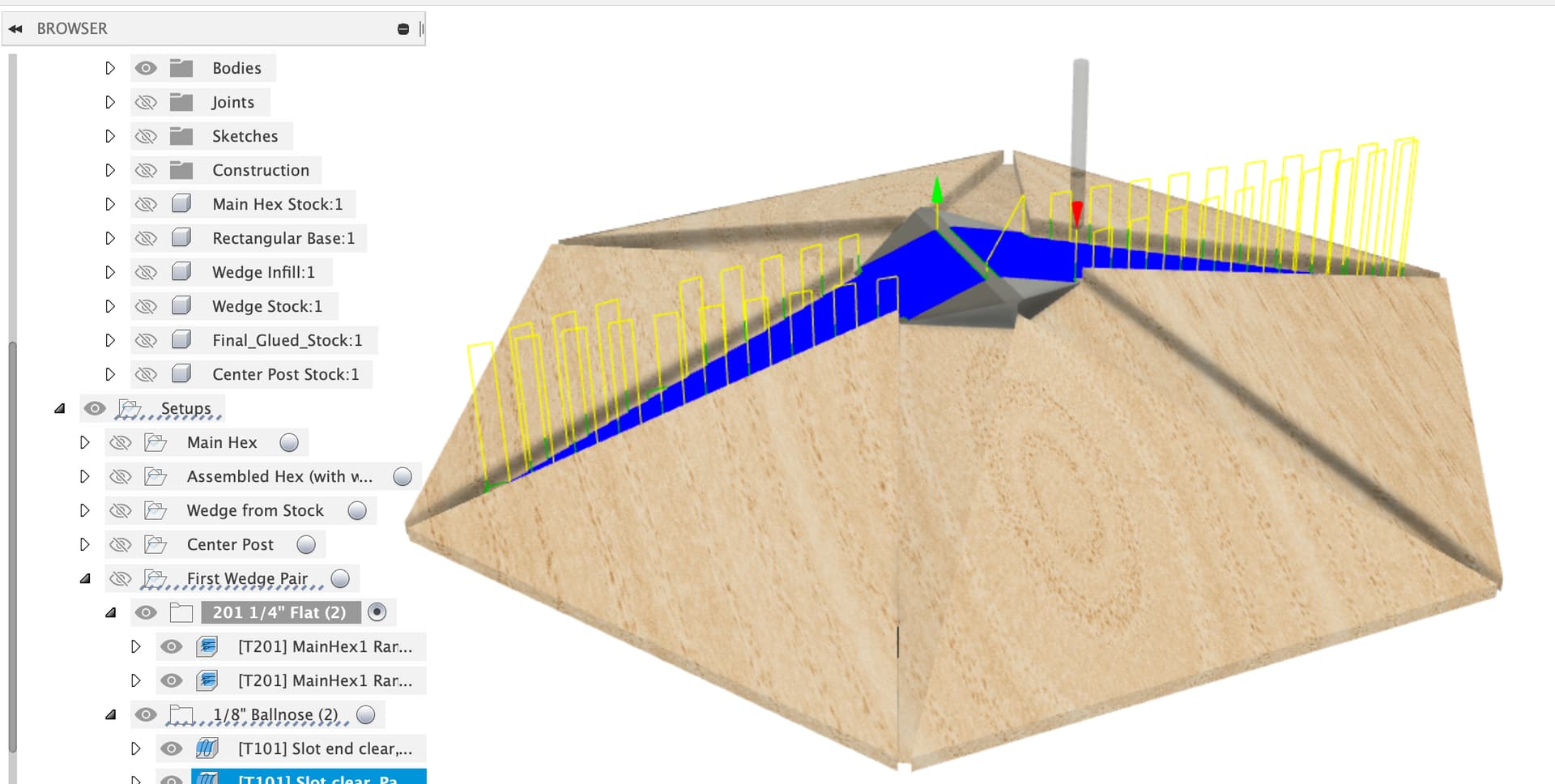
Finally, the 1/16" pass to clean up the walls for the wedge
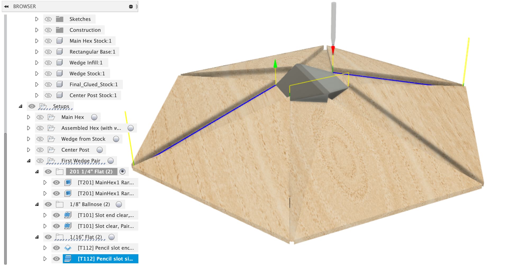
All that should give you a hex body with no weak corners to glue the first pair (1, 4) of wedges into
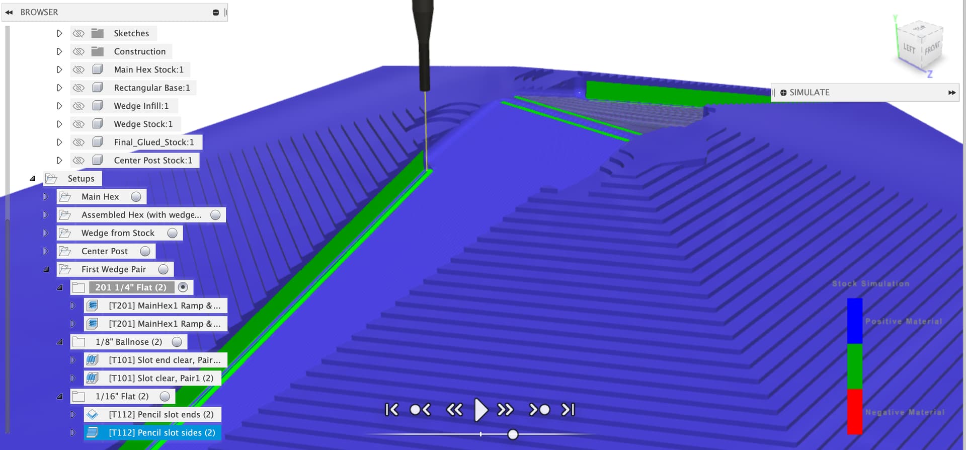
After this, you can run similar wedge slot paths to clear out (2, 5), glue them in and finally (3, 6), glue them in and then clear out the center post hole and surface the whole thing with the big ball nose bit.
Hope some of that helps.
LargeNewell v24 v7.f3d.zip (3.3 MB)
1 Like
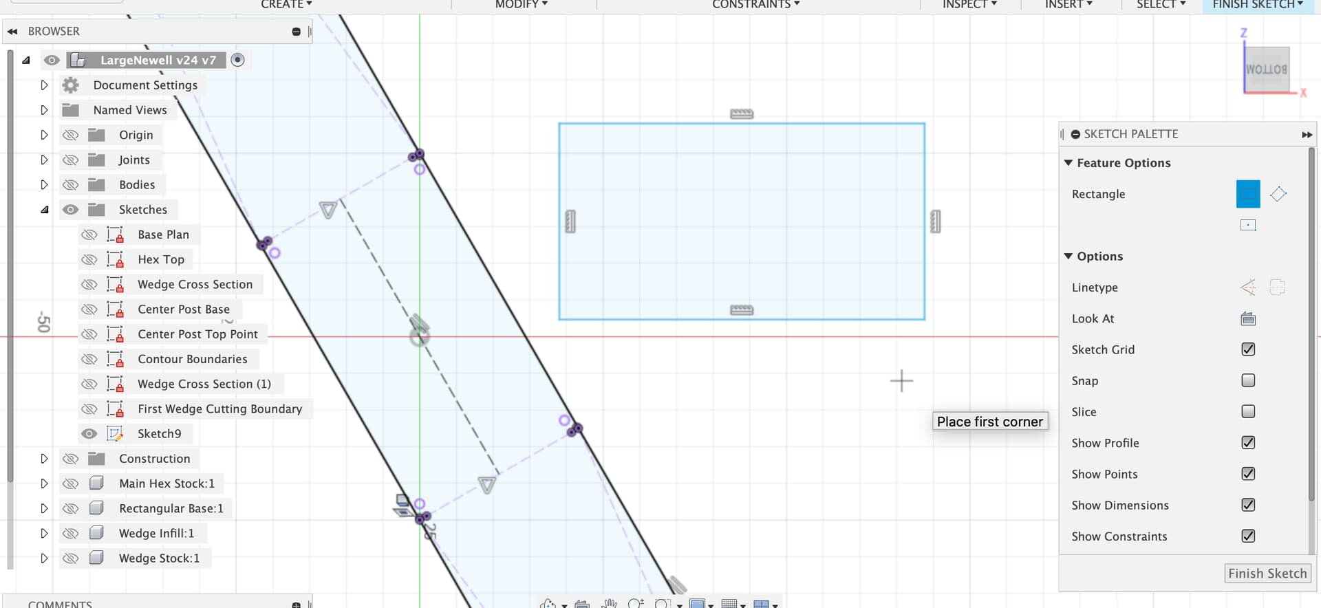
I like this approach! How did you create that sketch for the wedge pocket toolpaths? I need to do the same for the other two pair, right? Or, is there a way to copy the wedge pocket pair toolpath and then rotate it?
1 Like
To do the other 2 pairs of wedge slots we’ll want to add sketch boundaries for both of them and also probably a new version of the center plug for each of them too, did the history timeline for the center plug make sense to you?
I was doing a quick n dirty first pair so I created a new sketch on the Z origin plane, could have been on the bottom of the main hex body also, makes no difference in this case.
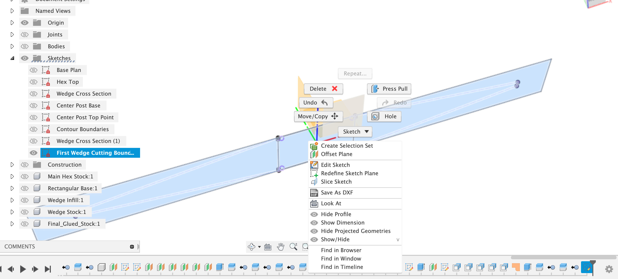
Then projected the two wedges I wanted to use into this sketch plane
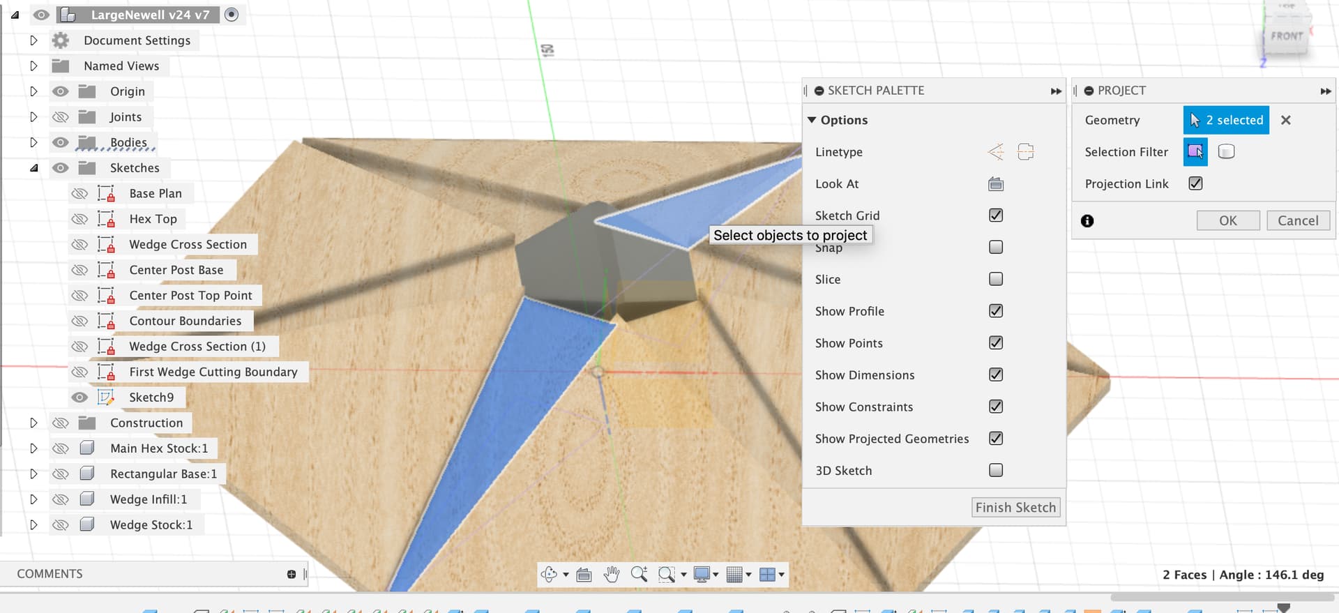
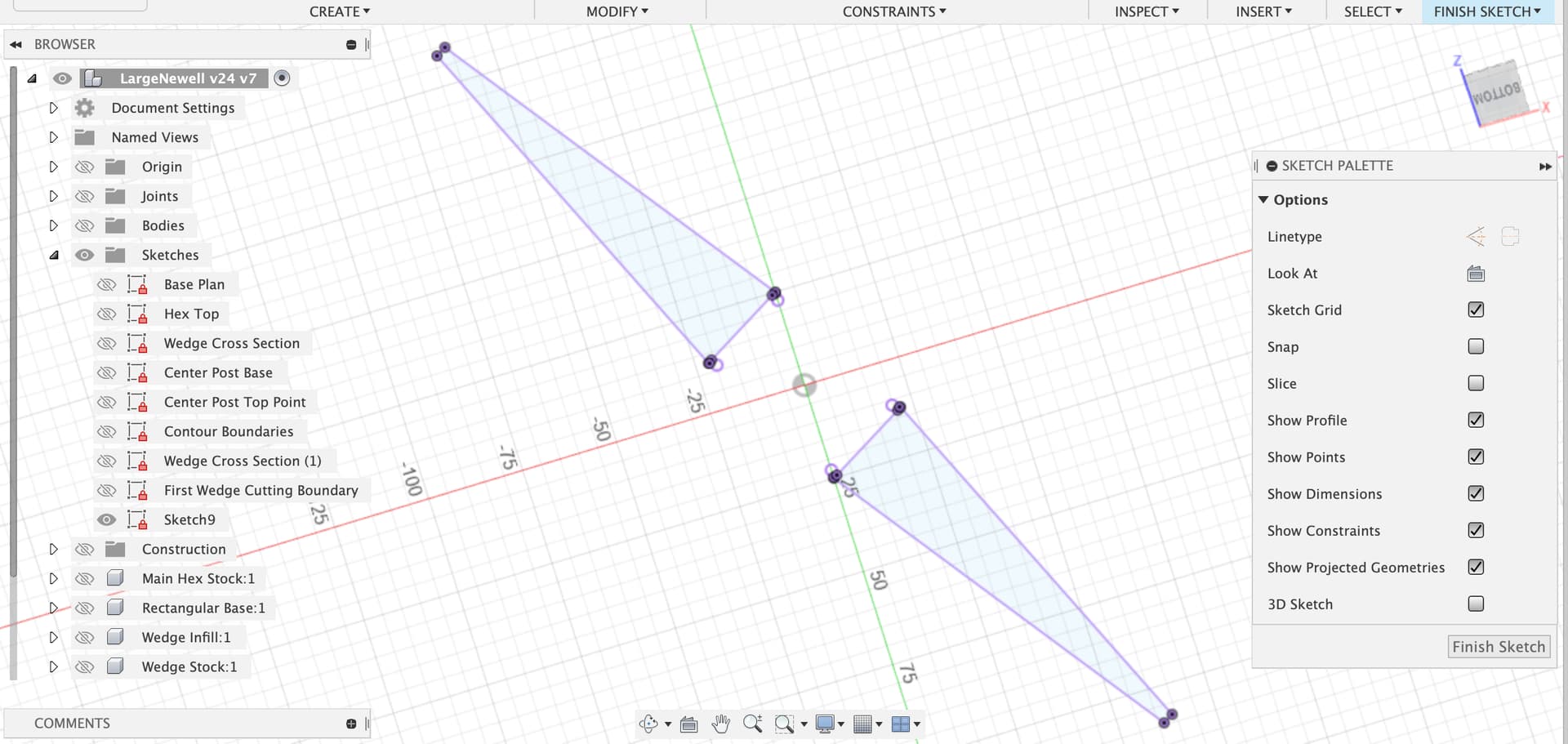
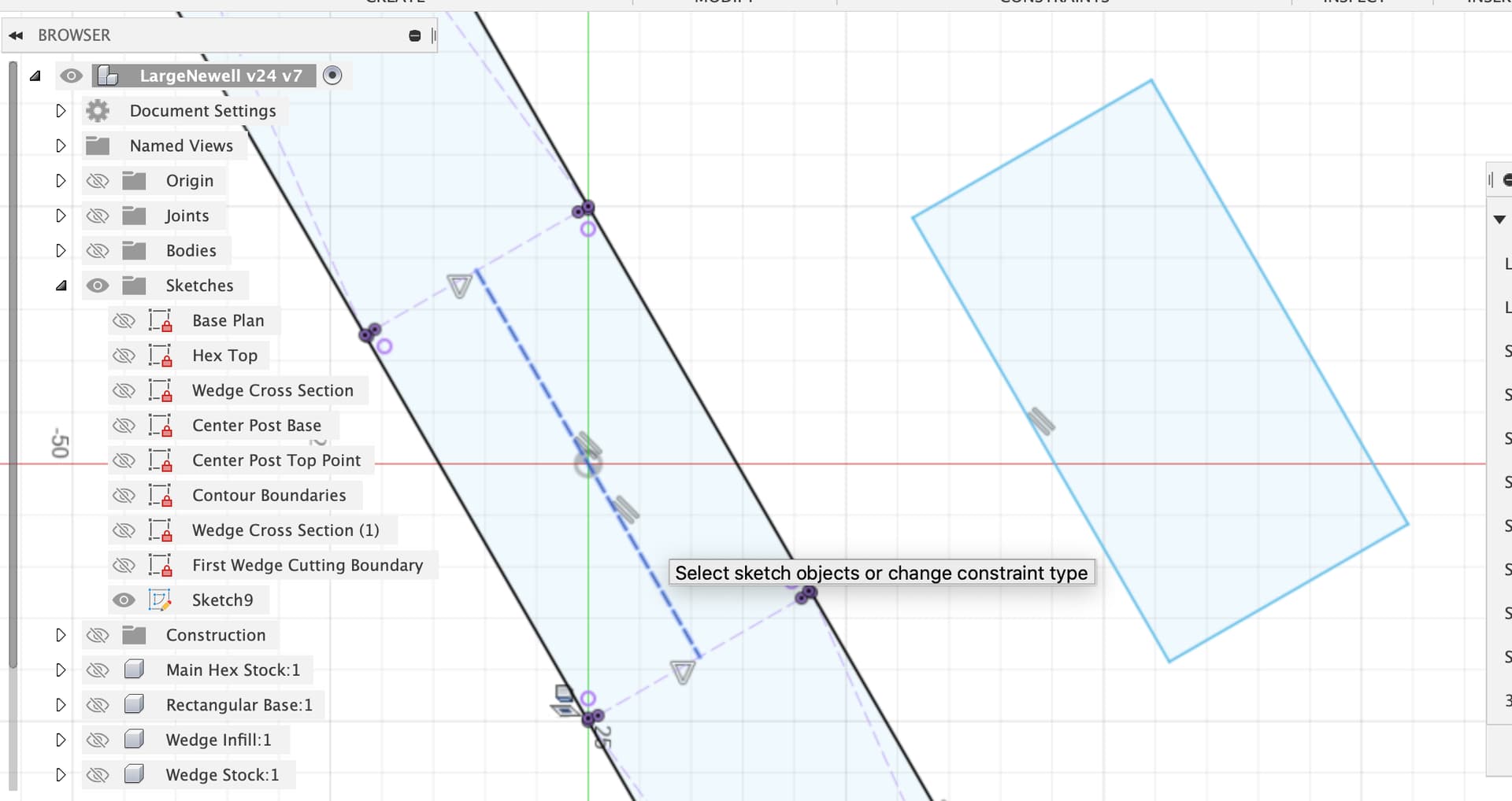
I converted them to construction lines to make selection easier later, then drew a rectangle around them and made it coincident with the widest points, for the other 2 pairs it’s more complex as we need a center line first
Use Perpendicular and parallel constraints to make this box of four lines a rectangle around the wedges
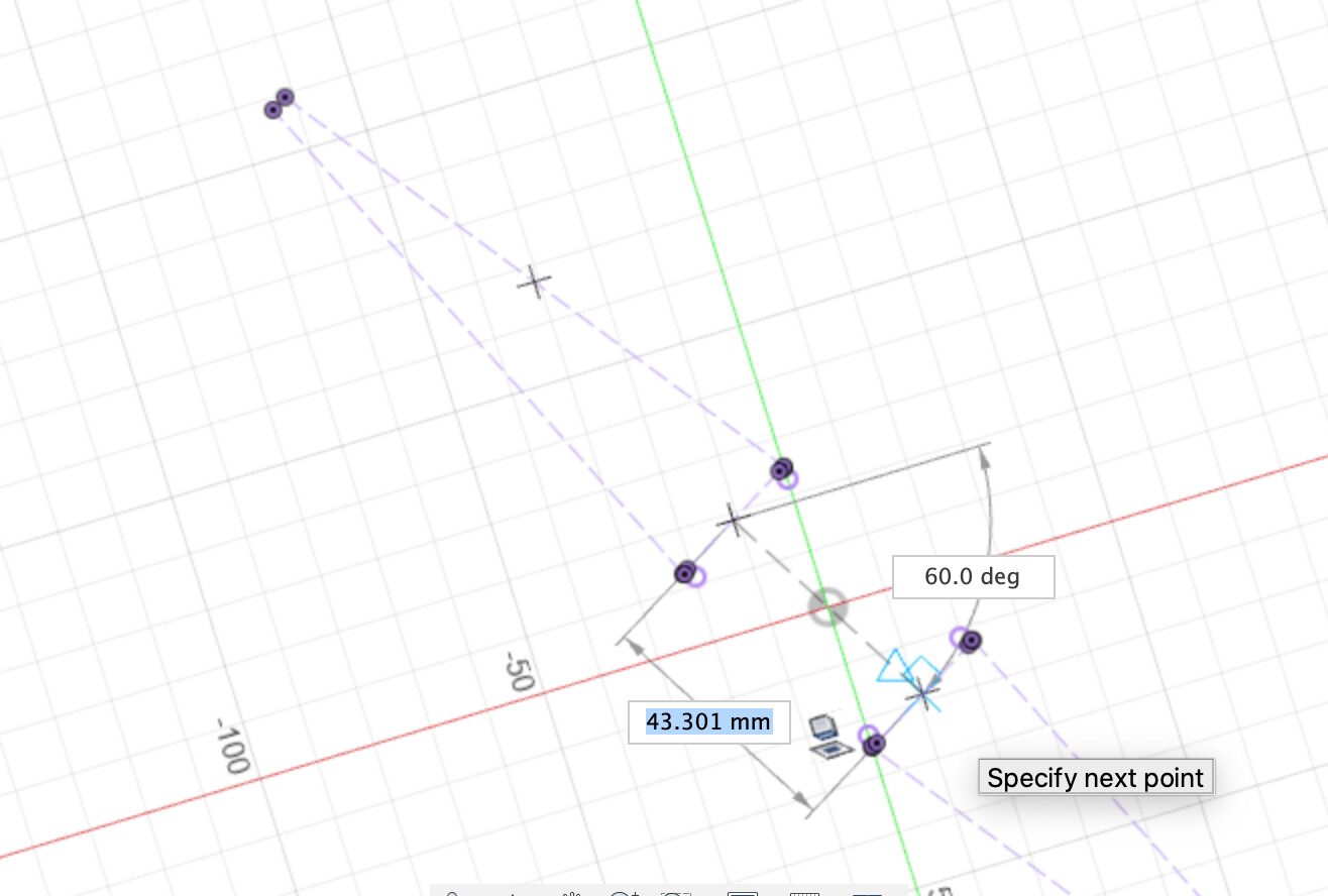
Then make it coincident with the widest points of the wedge projections, dimension it a bit beyond the ends and we have the main outline. We also want a box in the middle for the ballnose toolpath.
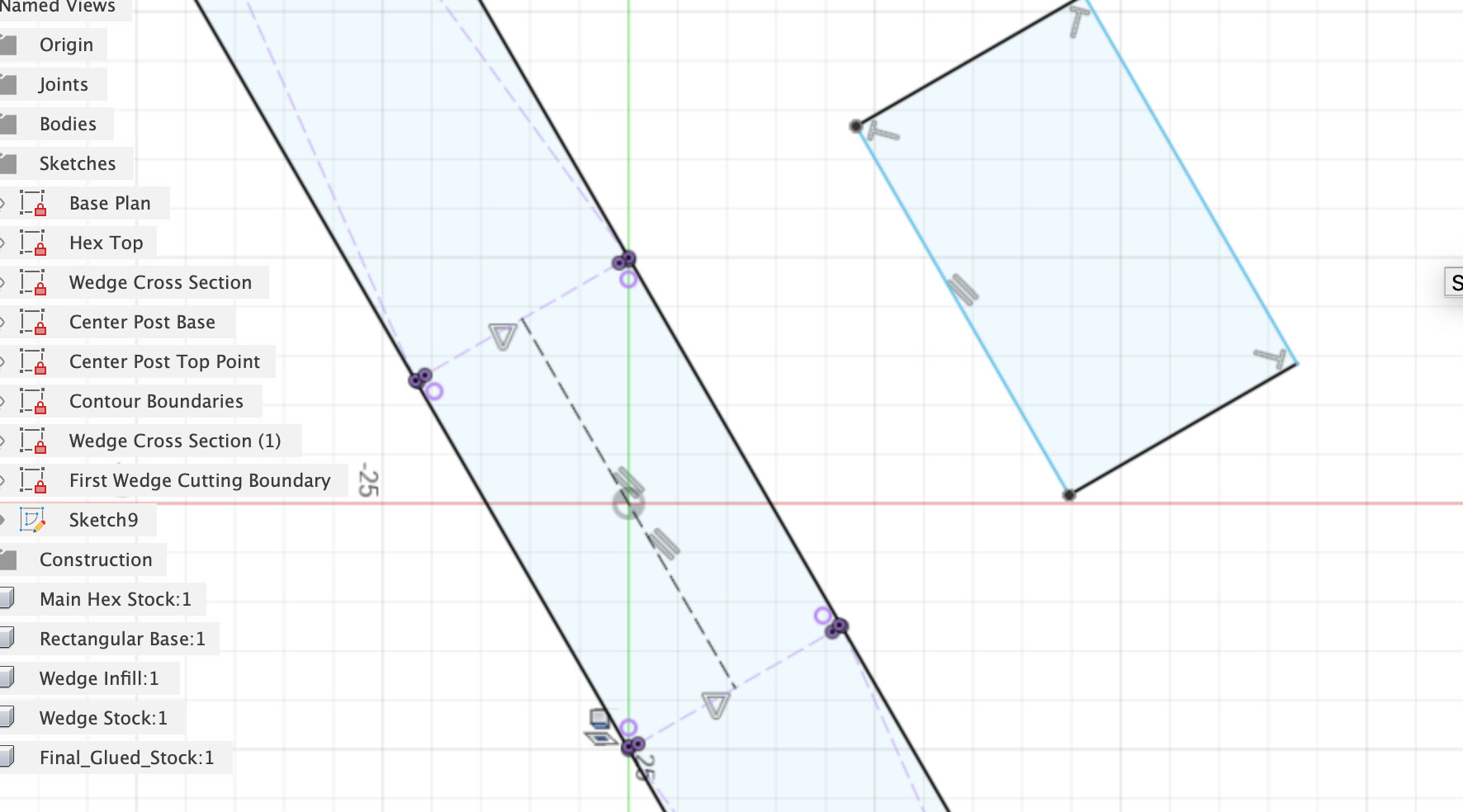
This is a bit more fun again at the angle, another way, draw a rectangle
Delete the horizontal / vertical constraints off it and set one side parallel to our center construction line.
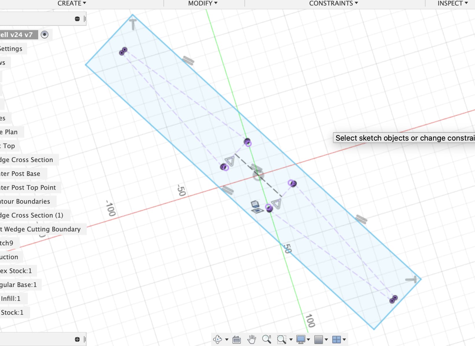
Use the perpendicular constraints to keep it as a rectangle
Then use the collinear constraints to lock it onto the two outer edges and the flat ends of the wedge projections
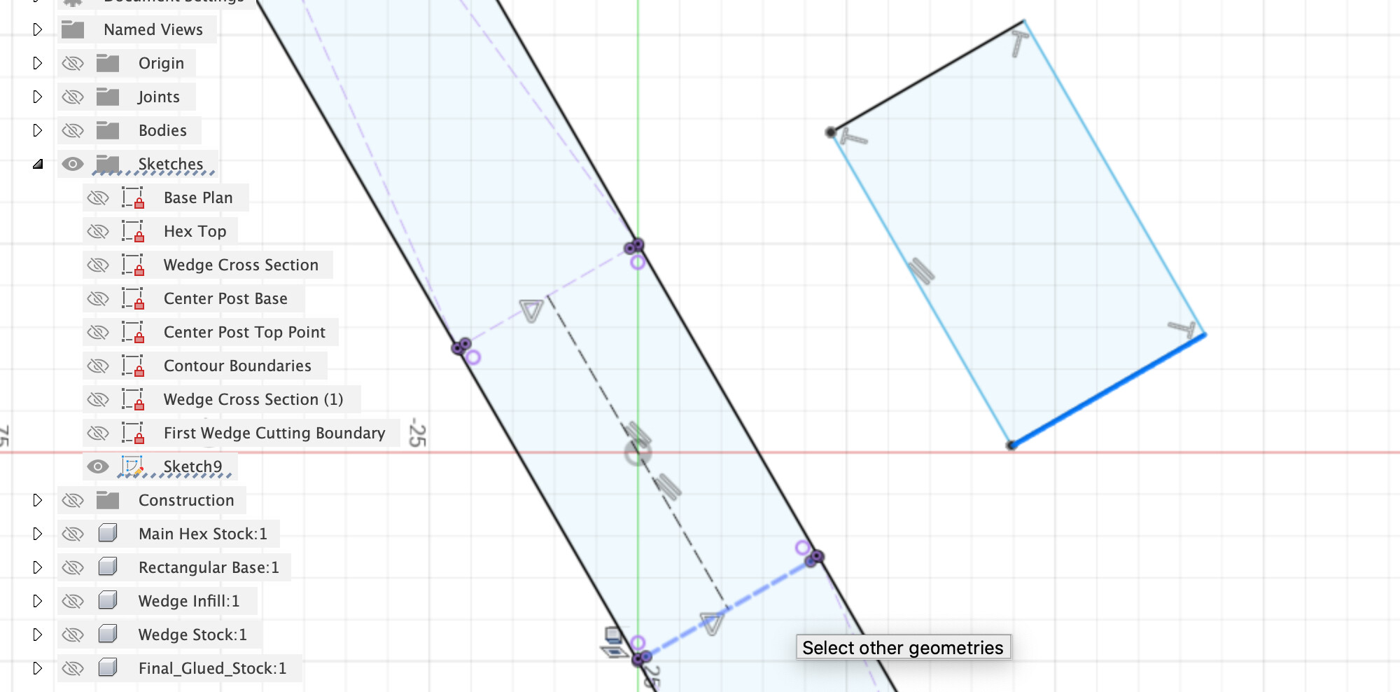
And now we have the box for the bits between the wedges
Fusion has many, many ways to achieve the same thing.
I’d then go into the First Wedge Pair CAM setup, copy all the toolpaths that work on the wedge slots and re-select the faces and boundaries they’re using.
Let me know if you get stuck, the combination of this project and my use of Fusion CAM has made all this quite complicated 
@LiamN, I’ve been away from this due to my wife undergoing (successful) surgery, but am back at it now (at her request!).
I’m lost. I followed the center plug and chopping it via the bottoms of the wedge pockets, but don’t see how it went from this:
to this:
But mostly, all that projection stuff is weird for me, and the resulting sketch doesn’t behave like I expect. For instance, I created a new sketch for a rotation axis:
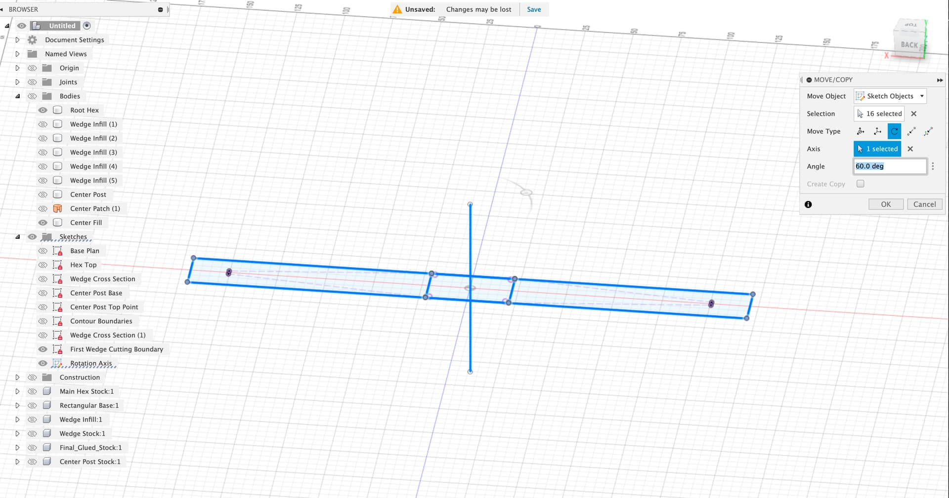
But, when I do the rotate, it looks like this:
Which makes no sense to me at all, as I created a perpendicular rotation axis for a sketch that’s all on one plane and yet the items on that plane are rotating all weirdly in 3D space.
I had hoped that rather than re-create all the wedge projections and extensions I could just rotate the resulting boundary sketch by 60 degrees and use that, but apparently not.
And, of course, the other thing that occurred to me is that instead of 3 sets of 2 wedges, it would be more ideal to do 2 sets of 3 wedges. The boundary approach is not intuitive to me - I probably would have considered building up three separate Hex Base bodies
- Hex Base with no pockets cut. This would also be the “final/assembled” hex base body.
- Hex Base with 3 pockets cut (every other one). Cut this after the first.
- Rotate/Copy #2 by 60 degrees and Cut this after gluing in 3 wedges.
My instinct would be to use the “rest machining” option so that each operation only removes the additional wedges rather than relying on boundaries to restrict.
But, either way, I do need help out of this!
So, I’m giving my idea a shot. First, I created a new component that is the join of the hex base with 3 wedges (every other one):
Now, I’m trying to create the toolpaths for this, but getting hung up after copying the setup and trying to modify. Here’s my file.
LargeNewell v27.f3d.zip (3.9 MB)
I’ll try again in the morning, maybe starting the toolpaths from scratch instead of the copy/paste.