My suggestion on that would be that I don’t like non-linked copies of things in my CAM, if you change the source object you really want the CAM objects to change too so I try to keep things connected.
My suggestion on that would be that I don’t like non-linked copies of things in my CAM, if you change the source object you really want the CAM objects to change too so I try to keep things connected.
OK, that makes sense. So, now I need to figure how to reproduce your projection of wedge slots, with constrained extensions and so on, unless there’s a way to just rotate a copy of them 60 degrees.
I hope she’s feeling OK soon.
Ah, there’s a simple answer to that, it didn’t ![]()
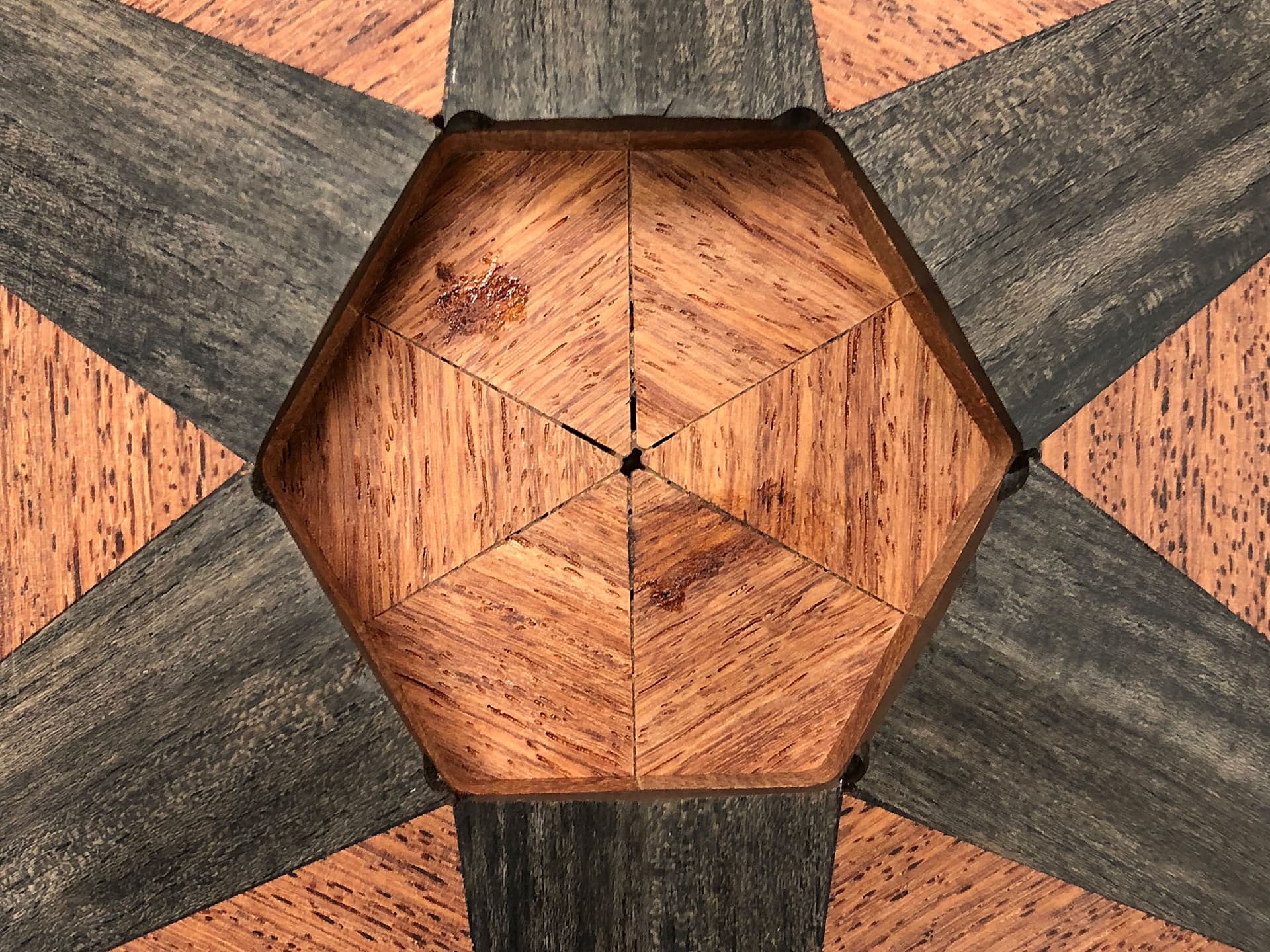
Those are two different things, the second is a 2 dimensional surface which was created between the 12 top edges of the wedges. The first is an extruded 3D body which is then chopped up with the split body commands.
Right, I think there’s several things all rolled into one here.
Projections are a simple idea but can have counterintuitive results. Basically the normal project works like this;
- Make the sketch plane the flat ground (rotate everything until this is true)
- Drop a vertical line from every point in the projected body, sketch, surface, whatever the thing in 3D space you’re projecting is
- The resulting lines drawn on the ground plane sketch by the vertical drops is the projected image.
It had not occurred to me to use rotations, that’s a good idea to save some work and some manual drawing of rectangles.
I’m not sure why your rotation went funky, are you sure the axis was normal to the sketch plane?
That also makes sense, two sets of jobs not three.
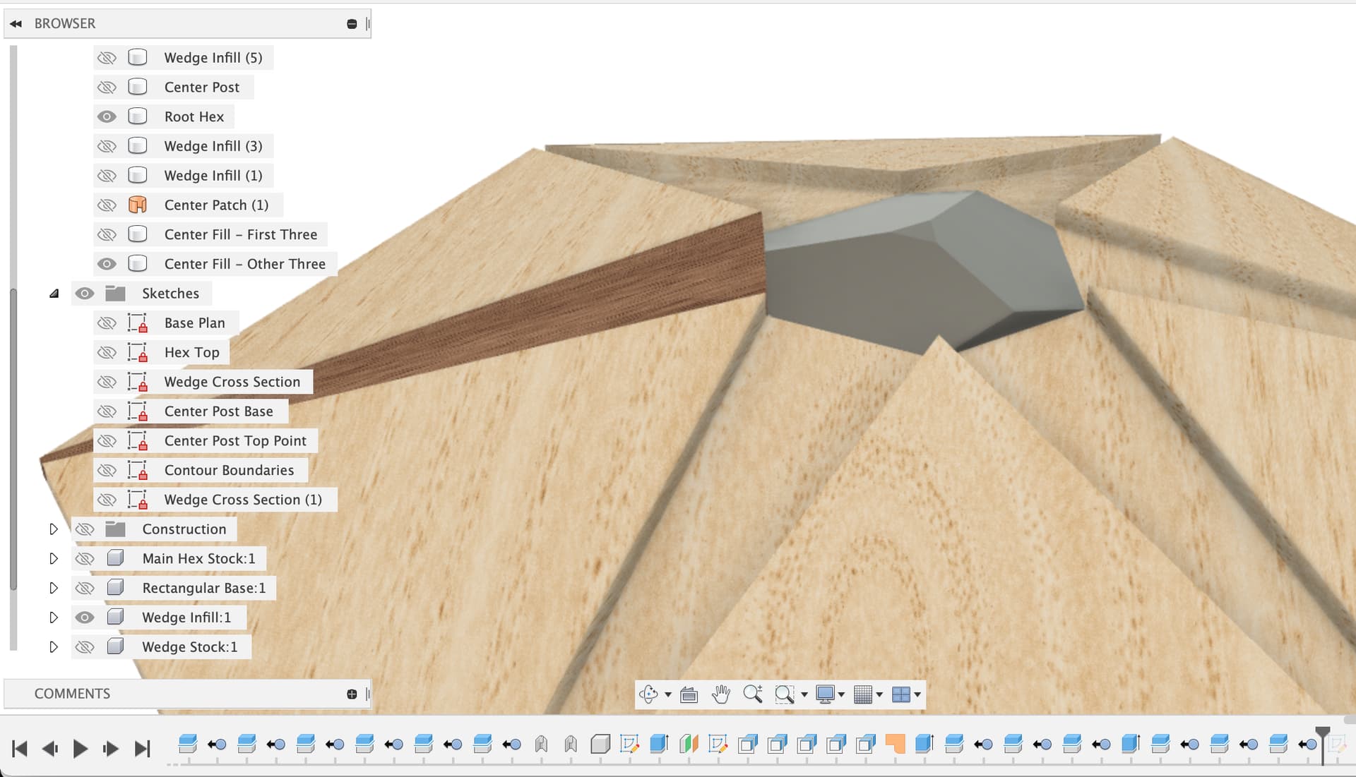
I went back and adjusted the center fill plug to have three wedge sections cut off instead of two
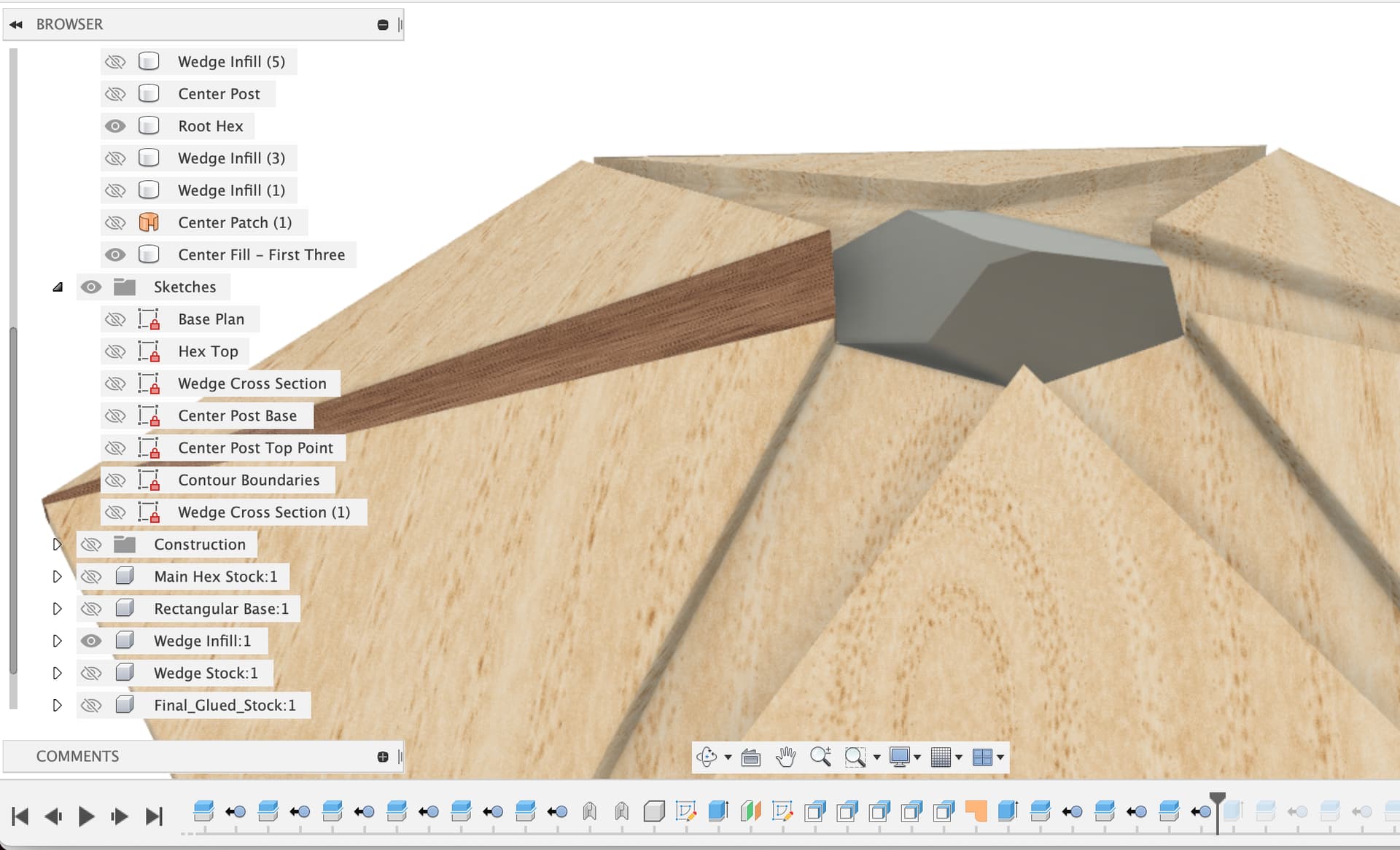
Then I made a second infill plug and cut it with the other three wedge planes
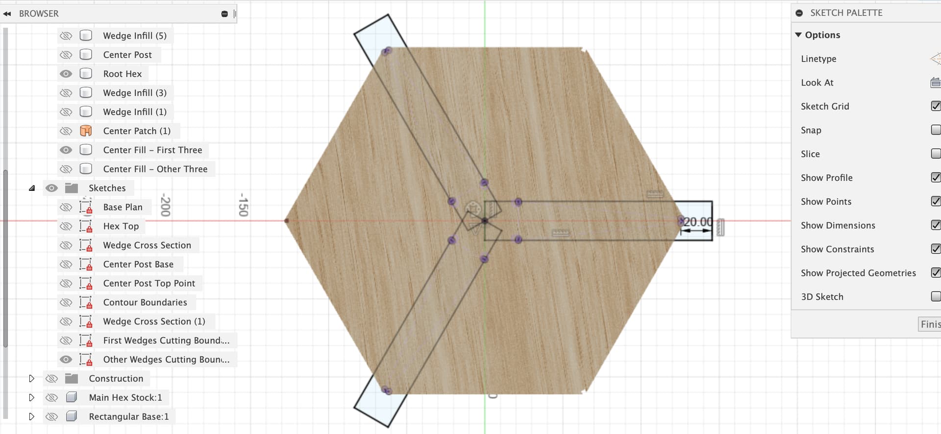
Now to the rotating sketches. I renamed the sketch with the two opposite wedge boundaries in it, deleted the projections and re-projected the three wedges we want to use.
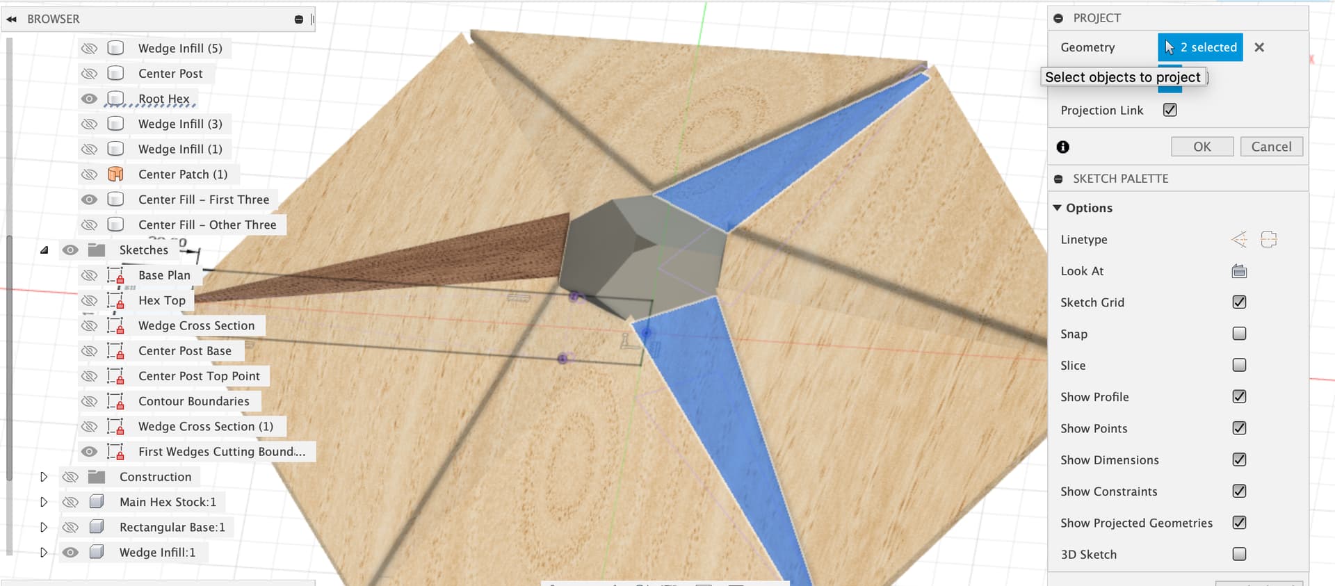
Then I trimmed the rectangle to stop at the center, made it coincident with the origin to lock it there. Now, the rotation trick, a circular pattern of three of that box covers the other two wedges.
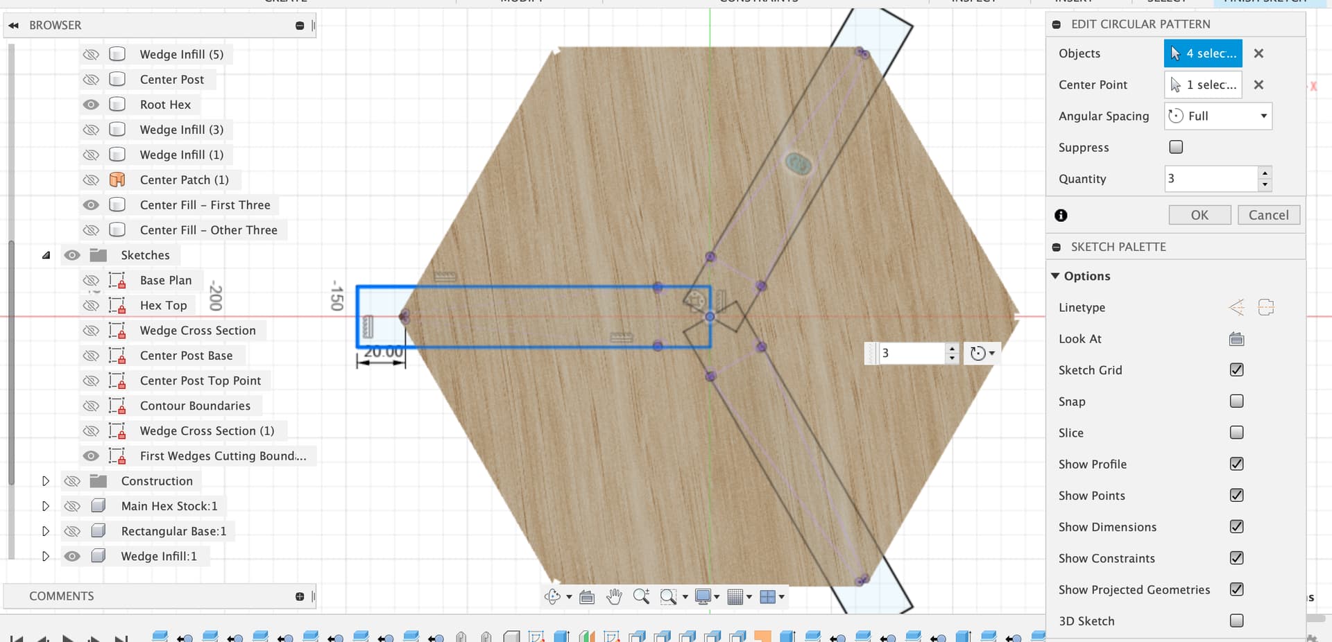
And the same thing for the other three wedges
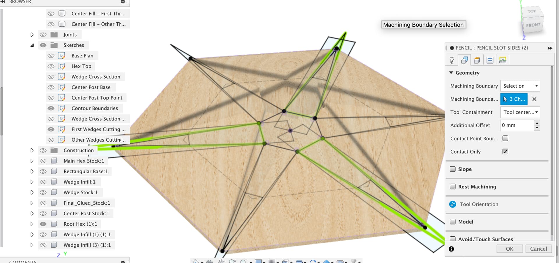
Over to CAM, I renamed the twin wedge job to Triplet and left the initial adaptive clear as it was.
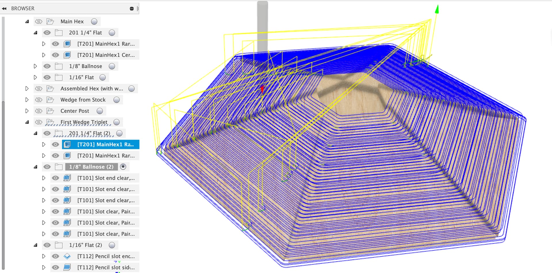
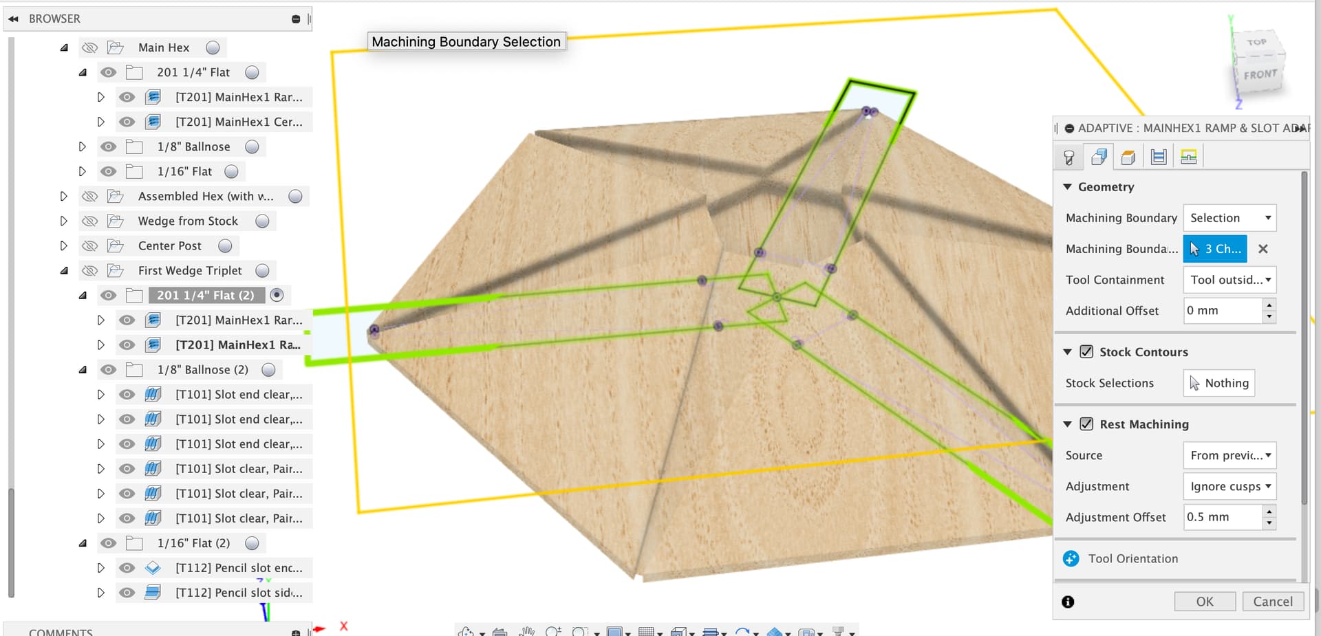
Then I edited the second adaptive to use the three rectangles in the updated ‘First Wedges Cutting Boundaries’ sketch.
Which gives the desired adaptive for the three slots (I hope)
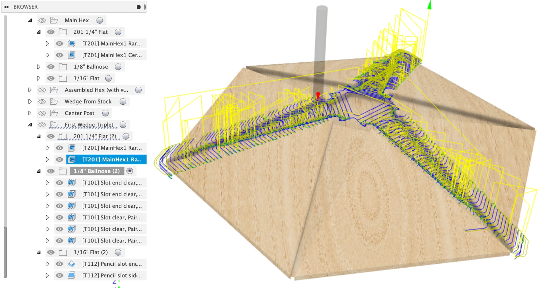
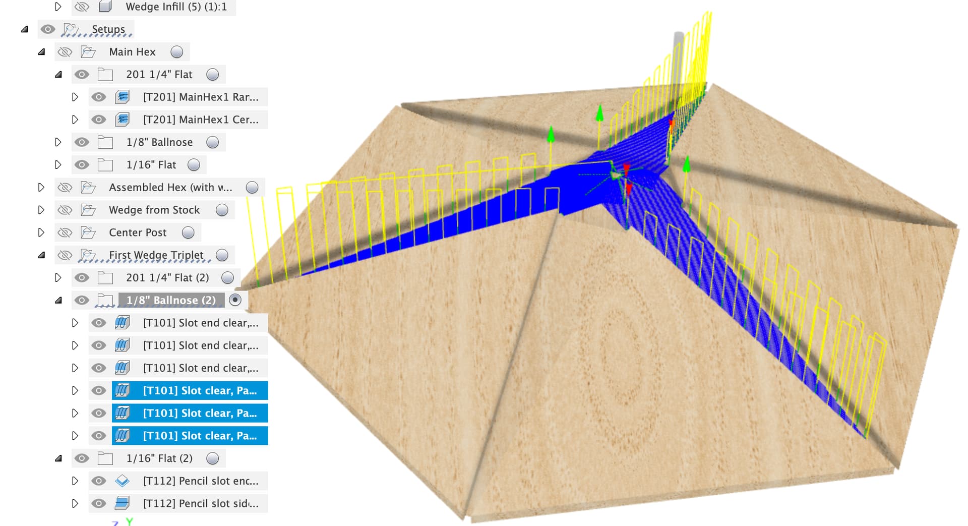
Then I broke up the slot end clearing to three separate jobs, one for each slot end
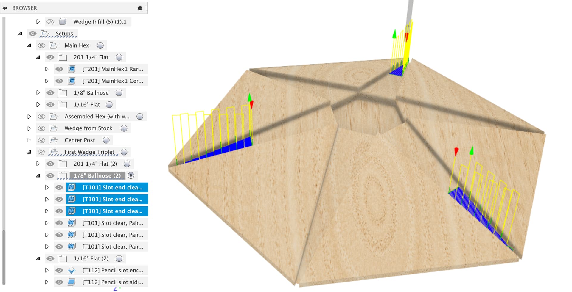
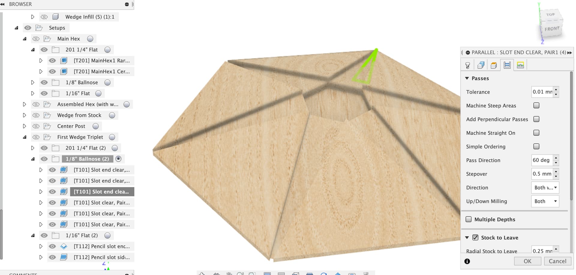
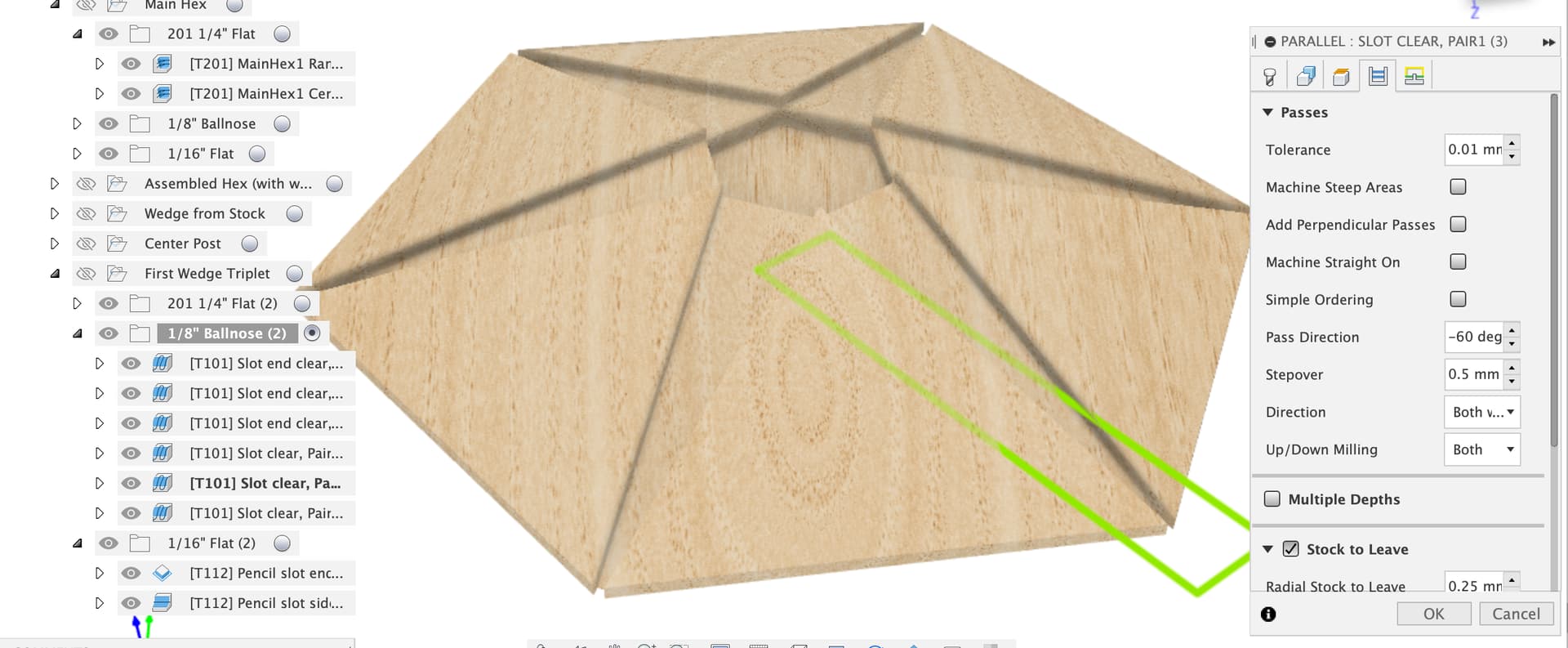
This was because we need to set the pass direction to match the slot centerline for each one.
Same trick on the three main slot clearing, updated to use the rectangles from our ‘First Wedges Cutting Boundaries’ sketch, one for each slot at 0, 60 and -60 degrees pass direction to run up and down the slots.
Then small updates to the 1/16" paths, just selecting the correct three contours from the ‘Contour Boundaries’ sketch.
I’ve left the copy of this setup which uses the other center fill plug and wedges cutting boundary sketch as an exercise for the reader ![]()
Does that make sense?
Here’s the file on Google Drive, it’s too porky to upload here now…
https://drive.google.com/file/d/1OicPLDZ7iODeCOjtbPqyodC8yqZkU6PO/view?usp=sharing
I was just in the middle of re-doing that when your post arrived. If I stick to the general move/rotate and remember to click Copy before entering 60 in the Z-axis field, it works. When I went to rotate only and selected a previously created line co-incident to the Z-axis, it didn’t work.
Looking at your new file now, thanks.
1 Like
OK, so after cutting the first triplet of wedge pockets, I glue in the wedges. When they’re dry I need to create/run a center hex pocket clear and then clear out the other 3 wedge pockets. And then re-clear the center hex pocket.
OK, on it now…
1 Like
Yep,
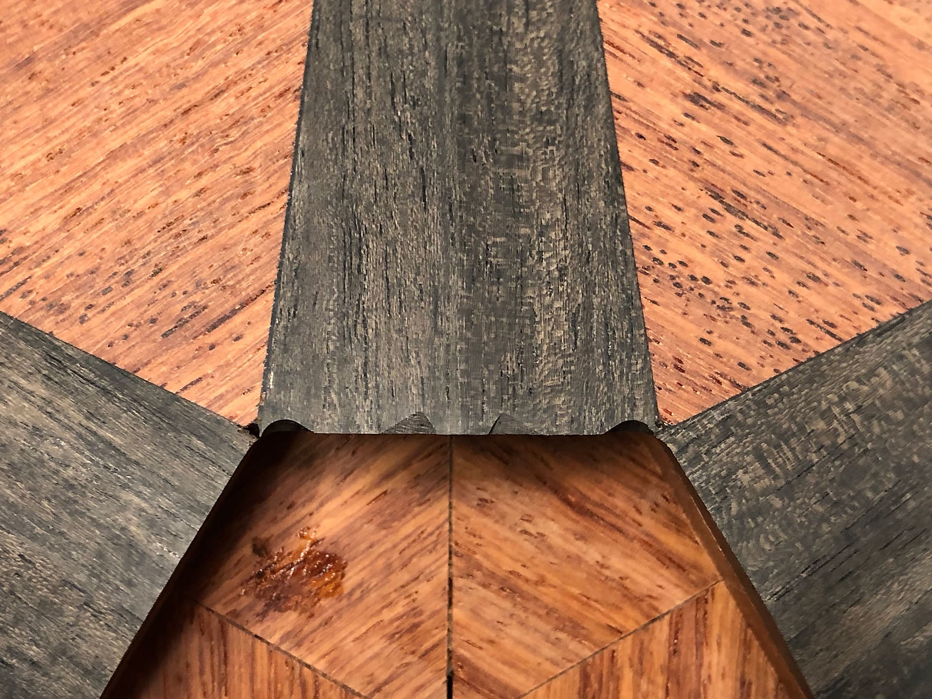
Except, I suggest not clearing the center pocket at all until all the wedges are glued in and there’s a complete perimeter of wedges around that pocket to avoid the chip out problems.
The extended ramps on the temporary center plugs allow us to cut through the overhang of the first three wedges when preparing the slots for the final three so we don’t need that center pocket cleared.
EDITED:
OK, I got the other center plug and got the ¼" slot clear to use the “other three” sketch for boundary.
Now I’m on the ⅛" ball mill paths. I can’t find the abbreviated slot boundary sketch to select. Here’s the first one you setup:
I copied the whole setup and am now trying to edit that:
These are the sketches available:
1 Like
Here’s my file so far:
(I deleted the old MainHex since we’re not using it, but I still have a version with that in it, just in case).
Making good progress,
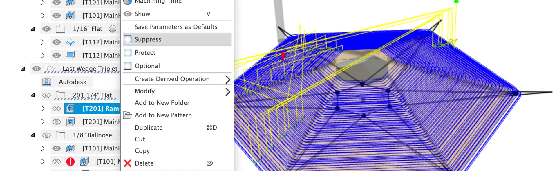
I suggest deleting the main Ramp Adaptive clear (you already marked it do not run), you can also suppress a toolpath if you think you need it later.
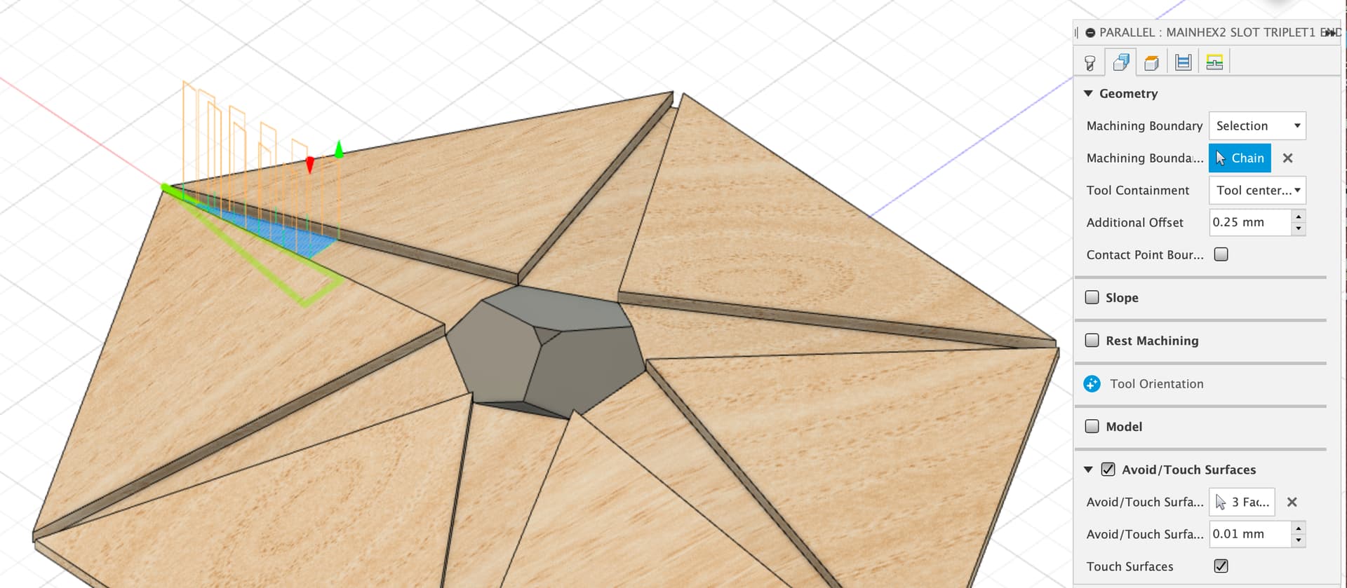
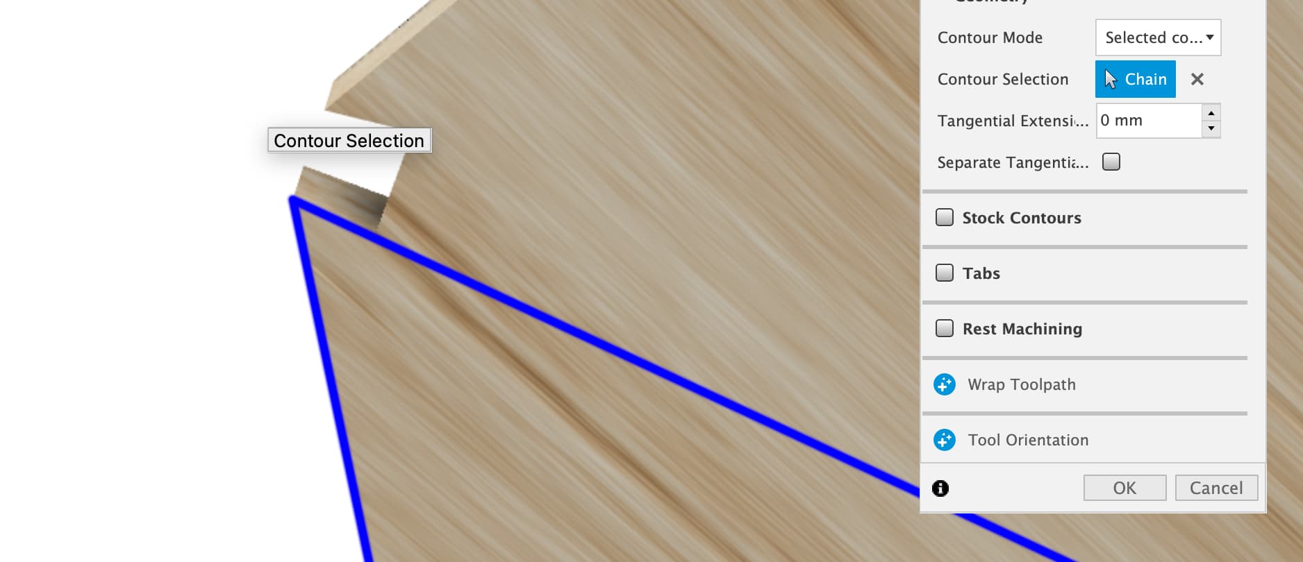
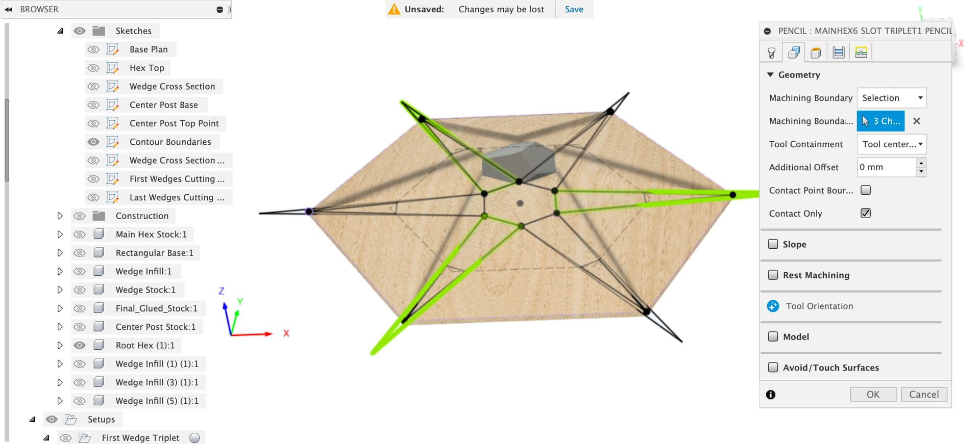
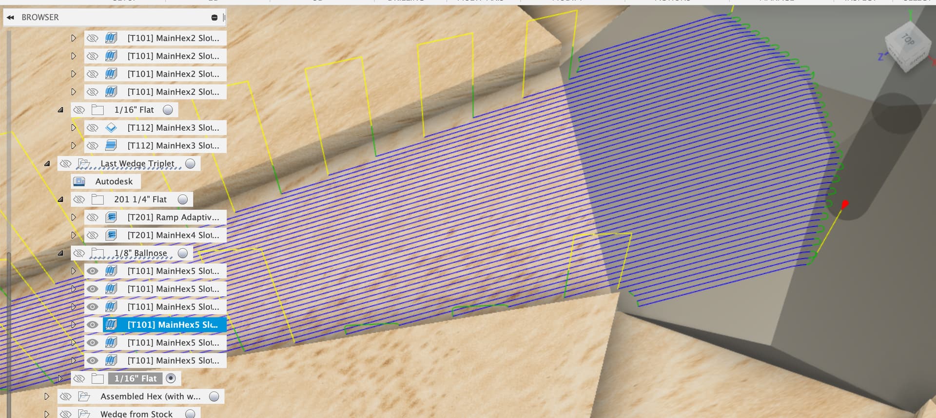
On the 1/8th ballnose toolpaths, the boundaries are the assorted triangles in the ‘Contour Boundaries’ sketch, here I’ve reselected the next one round
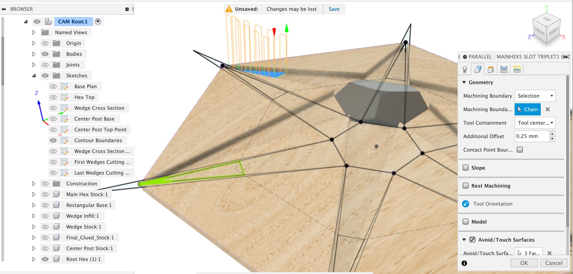
Also reselect the face that should be included for this toolpath
and remember to change the pass direction on the passes tab to have these go up and down the slot too.
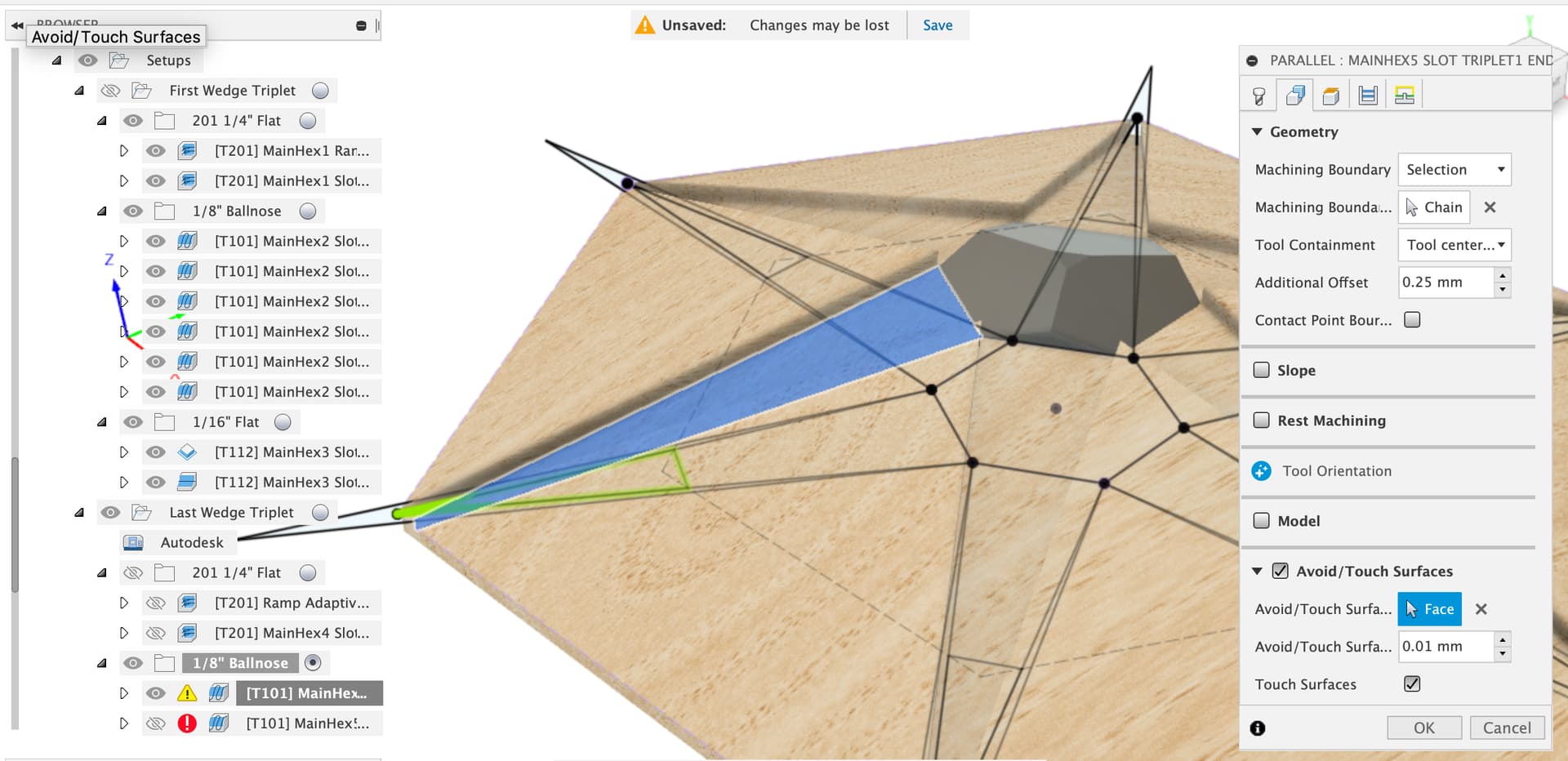
Similar process for the main ballnose toolpaths, machining boundaries from the ‘Last Wedges Cutting’ sketch, and reselect the pairs of faces, slot and center fill
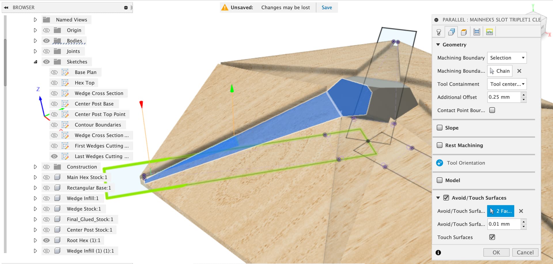
Again, remember to change the pass direction on the passes tab to go along the slot
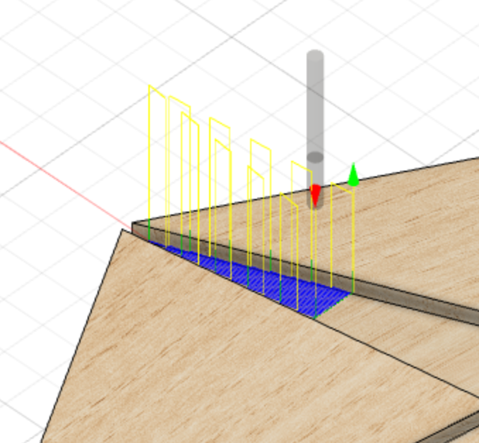
Moving on to the 1/16th bits, the selections for those are a bit ugly and funky because I had real trouble finding a toolpath that would do a single pass down the edges of the wedge slots so we have a bit of a bodge to clean the ends out.
For the pencil-ends toolpath, we need to select just the three edges of the end of the slot where it cuts through the base.
From the bottom, select one side of the square-ish cut-through, Fusion guesses the rest
Click again on the edge to say “no” and select the open contour symbol
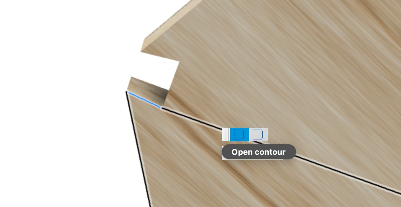
Then click over to the opposing edge
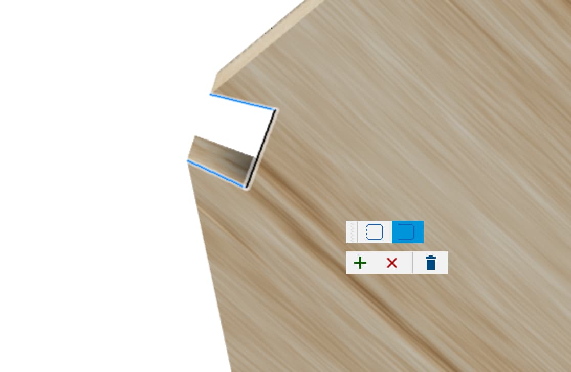
And hit the + to say your new contour is the one you want
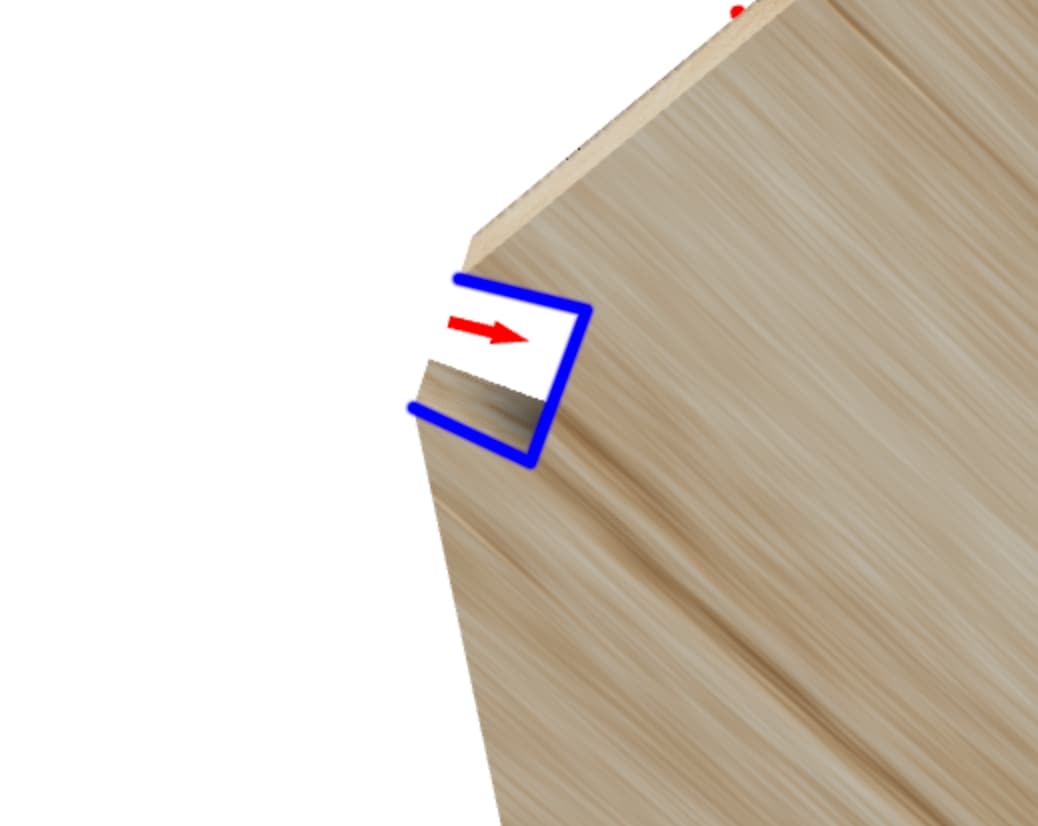
And then check the toolpath
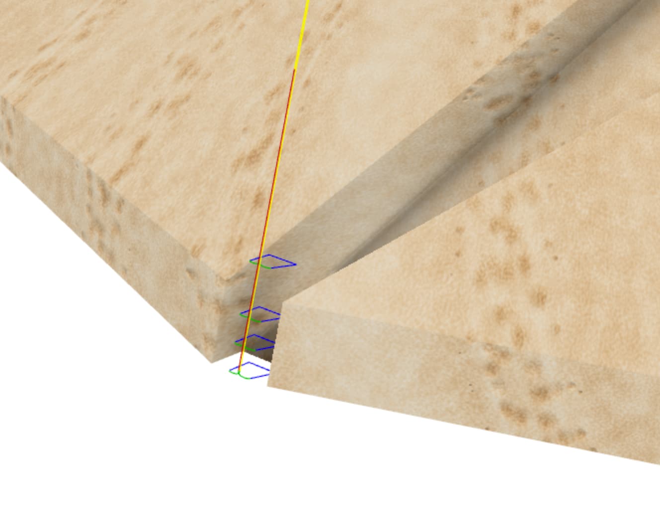
Remember there are three of these.
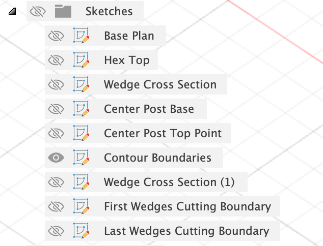
Finally, the pencil toolpath, the contours for this are in the ‘Contour Boundaries’ sketch again.
HTH
I was afraid to do that since the Slot Adaptive clear has checked “Rest Machining from previous operations” and so I thought I needed that previous operation to prevent additional air cutting.
What’s the trick for making that selection? Is there some order of showing sketches or something? I tried a dozen times yesterday and couldn’t do more than select everything in the Contour Boundaries sketch. This morning I went to make a screen grab video to show you want I was seeing - and of course it worked. I don’t know why. I’m about to try it for the other 5 toolpaths there…
You had the 3 faces selected, but since each ⅛" ballmill toolpath is only doing one face, I just selected that one face independently for each. I guess the 3-face selection is left over from you trying to do them all as one toolpath and copy/paste to get the other 2 when there was some reason you couldn’t?
Since I’m working in a copy of the “First Wedge Triplet” toolpaths, won’t that already be set properly?
Thanks again!
1 Like
Ah, good point, and we can’t just merge the setups as we are gluing more wood into place between setup jobs. Simplest thing is probably, as you say, keeping the big adaptive and not running it.
Yeah, sometimes you just need to take Fusion out to the woodshed for a good restarting.
One thing that can make this more difficult is having more things than you absolutely need visible, turn off every sketch, body etc. and just make the one sketch you’re trying to select visible.
Erm, general untidiness? ![]()
You’re right, each one needs just the outline and matching face selecting, I think I had them all but then remembered that I had to set the pass direction individually and went copy paste as you say.
Hah, it will be, if you want all the toolpaths to be running 60 degrees off from the centerline of the wedges ![]()
OK, is this the desired target then:
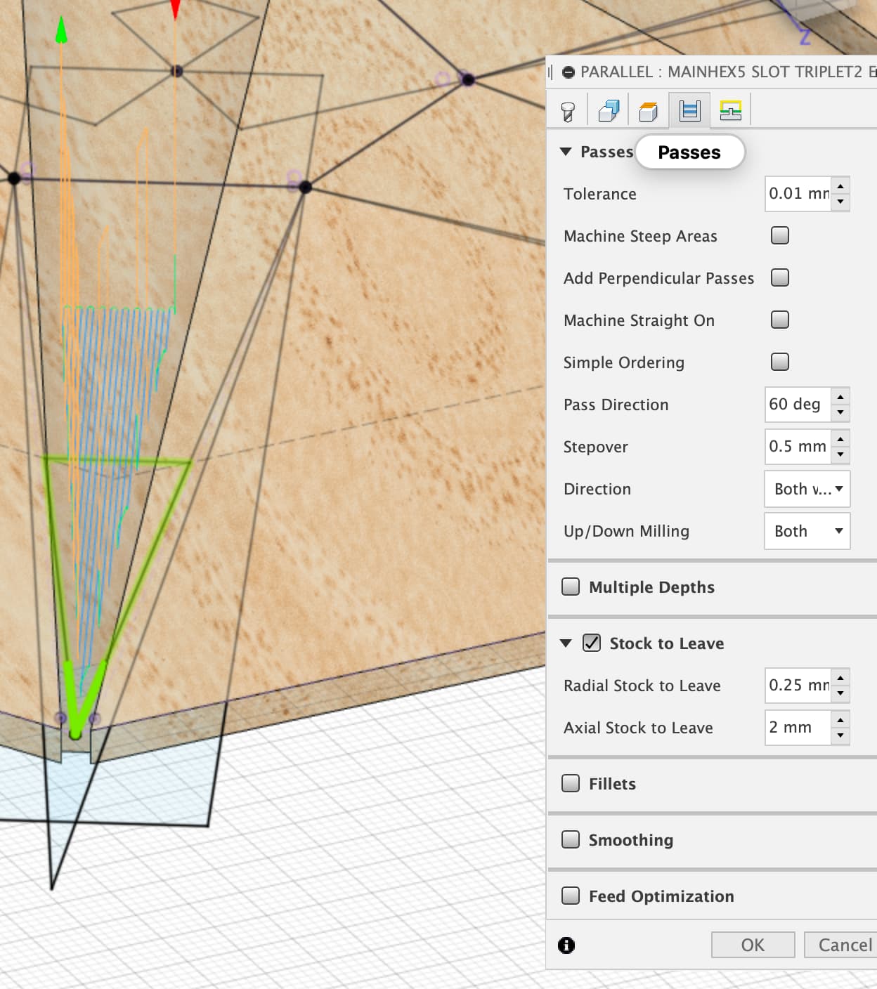
Or do I want the passes left to right?
And do I want to check any of the boxes above “Pass Direction”?
thanks yet again.
NP,
That looks right yep.
I don’t think it’s necessarily a requirement to machine straight down the slot, these aren’t finishing passes but it seems to be fastest and in the simulations seems to give the best coverage of clearing out the glue base for the wedge.
As for the other boxes, I don’t think so, but I don’t think I’ve ever used any of them so I may be missing something…
OK, so I thought I got all that done, but there’s a piece of the wedge slots that isn’t clearing:
And when I checked, it wasn’t being cleared on the first triplet either.
File is here if you have a chance to check: Dropbox - LargeNewell v28C.f3d - Simplify your life
thanks - I feel really close now!
1 Like
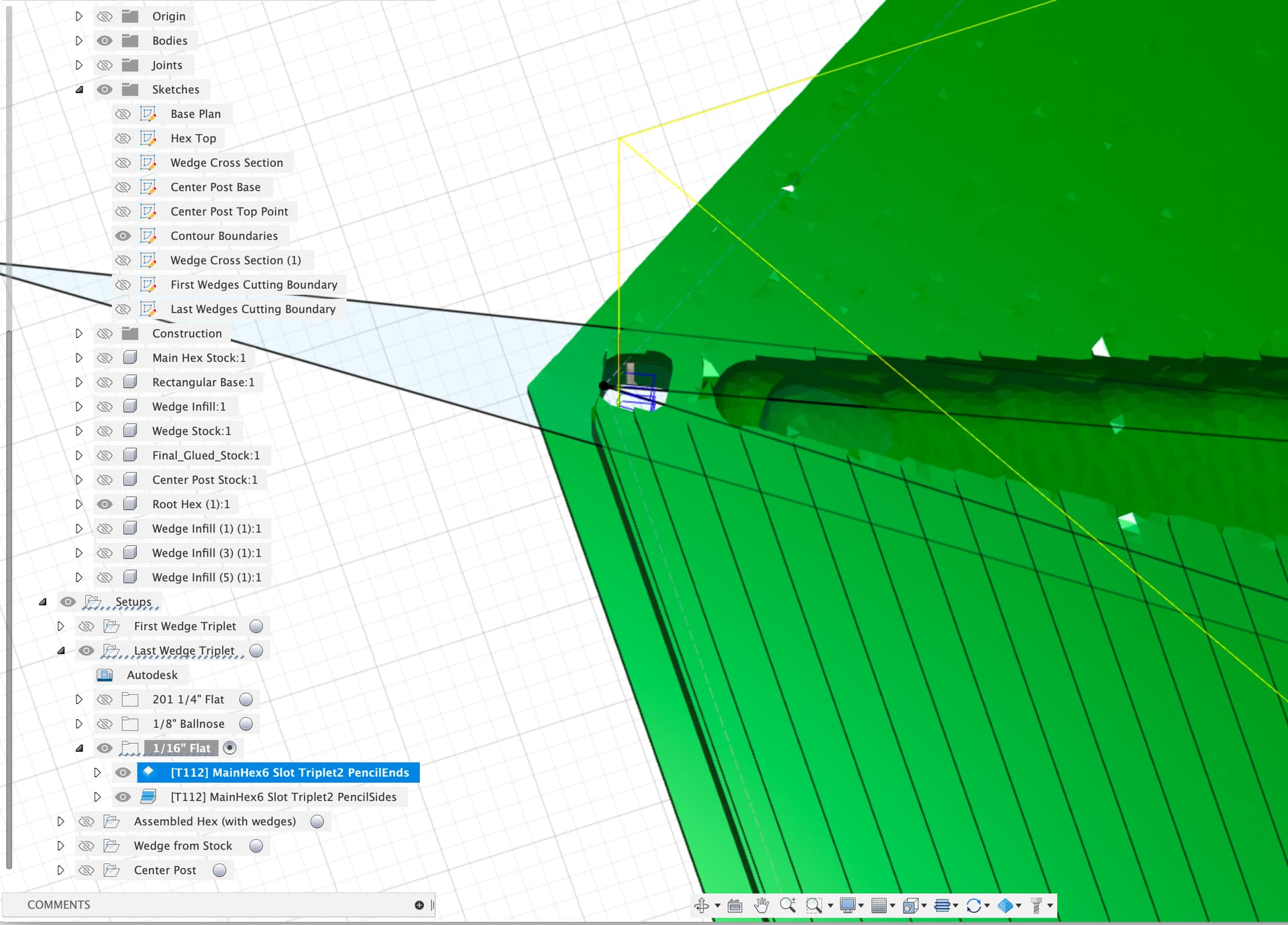
Ah,
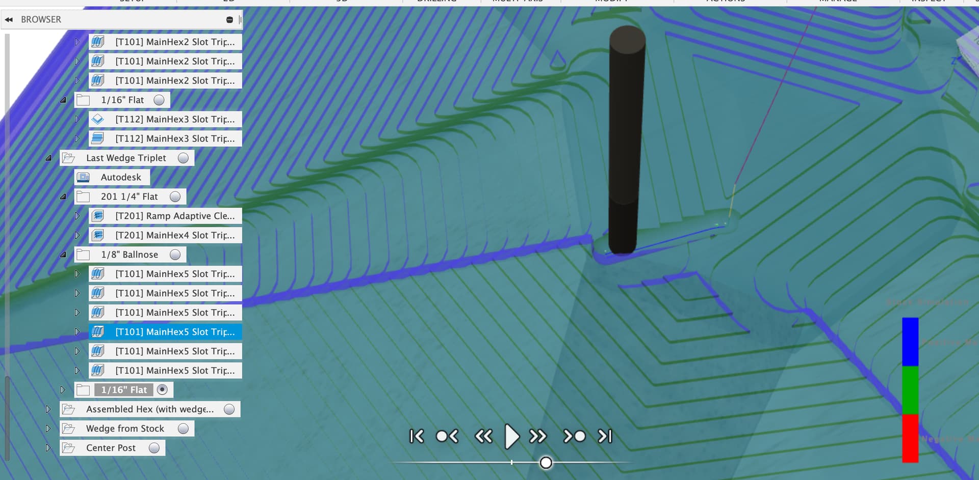
Yes, this toolpath is what the big starfish outline is for, the smaller triangles limited how far the 1/16" cutter could go.
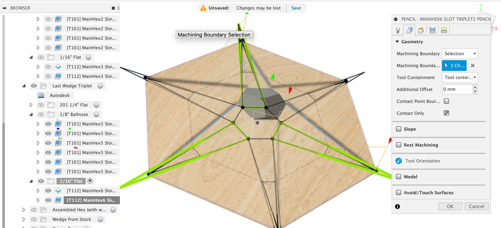
With the big starfish selected instead;
It may be worth running a first pass of this final pencil path with, say 2mm of axial stock to leave, or just running the feed rate nice and slow to avoid the expensive crunchy sound of small diameter cutter at too high a feedrate. The 1/8" paths leave that nasty uncleared bump at the bottom.
Hey, just a quick update. Ran the new toolpaths on some redwood again. I didn’t have wedges to glue in, so I decided just to run all the paths up to the main ramp clean-up with the big core box bit.
Look ma - no corners cut!
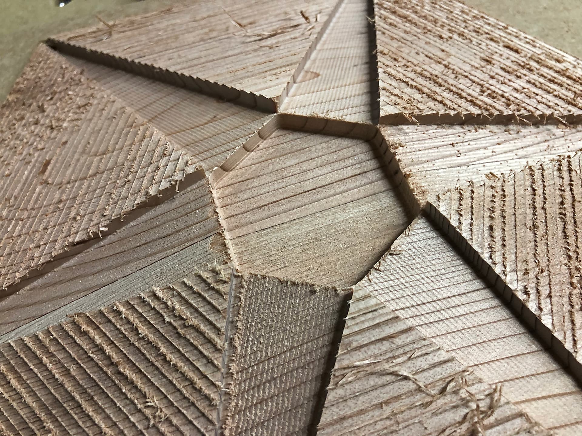
So, with the glue-ins and especially with the stronger wood, I do not anticipate any problems with the corners being cut. And almost certainly could have gotten away with cutting all 6 wedge pockets at once, after the ramp was rough cut, but before the center hex pocket was cut.
Looks like I’ll be cutting the expensive wood tomorrow!
Thanks again, @LiamN!
5 Likes
First the good news:

But, on close inspection, there is an issue:
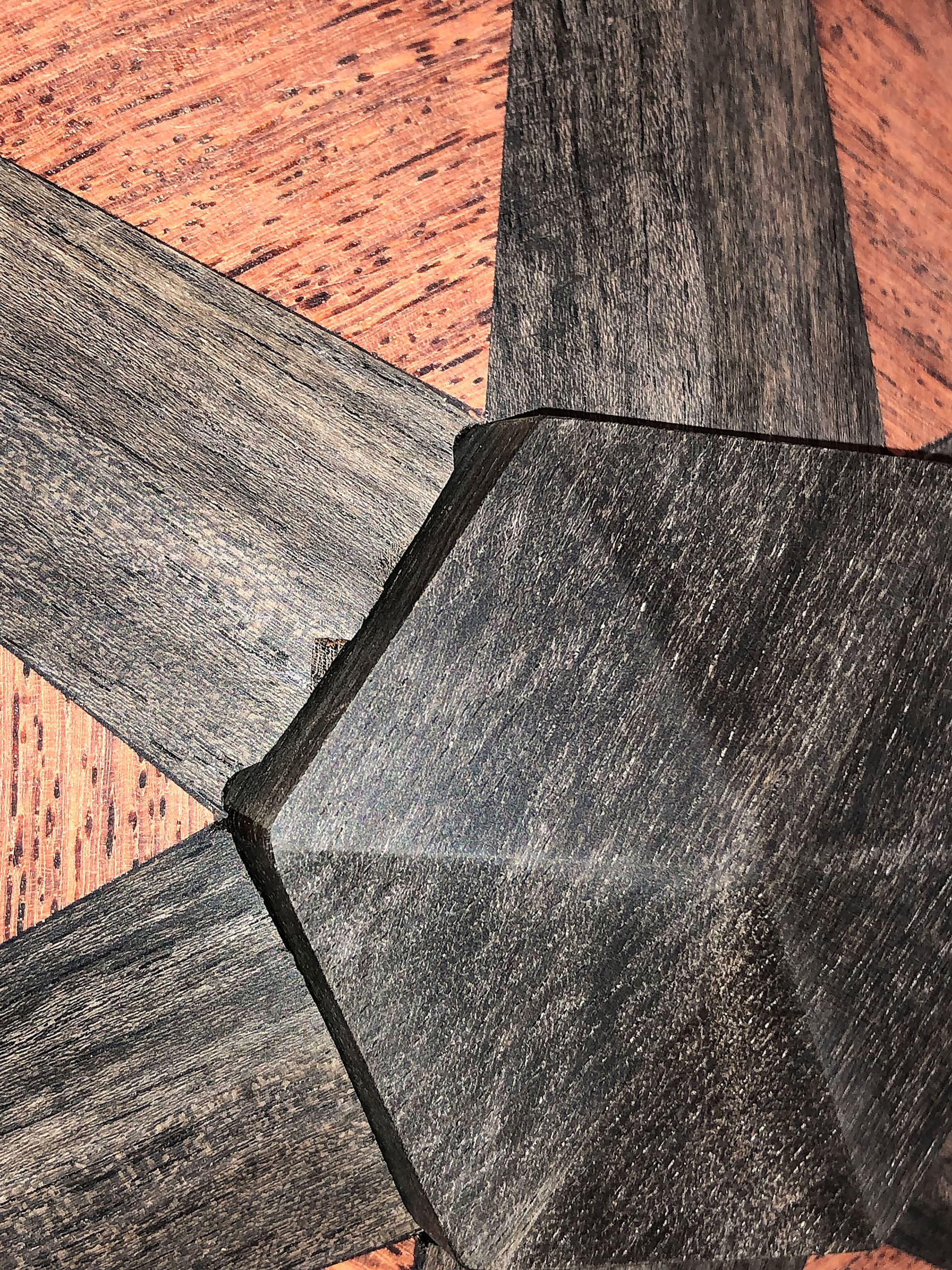
This is coming from the pass that clears out the second set of wedge pockets after the first set has been glued in:
For some reason, that clearing is a bit too aggressive. I’m investigating now. My first thought is that maybe the projected boundary is too large.
2 Likes
Nice work, starting to look good, is that the finish from just the ball cutter on the finish pass or did you sand it flat too?
I see the notches and I think I know which toolpaths are doing the damage, the flat cuts near the apex of the wedge seem to be coming from the adaptive clear, the rounded notches I think are coming from the 1/8" ballnose that finishes the bottom of the wedge slot
Now if only there was some way to tell Fusion “No! stop that you muppet, that’s my finished model!” 
Going back to the CAM setup, we have only selected the hex and the center post fill as the model so Fusion doesn’t know that it’s being dumb.
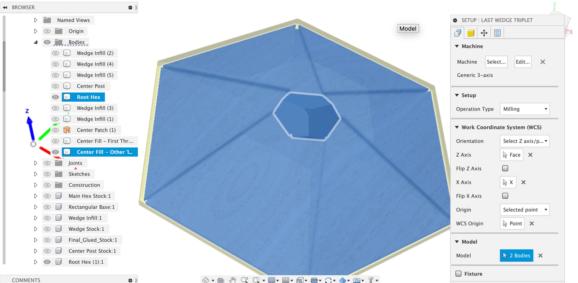
If we show the now glued in wedges
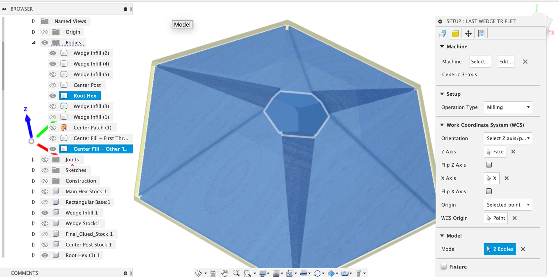
And add them to the bodies selected as “Model” for this setup
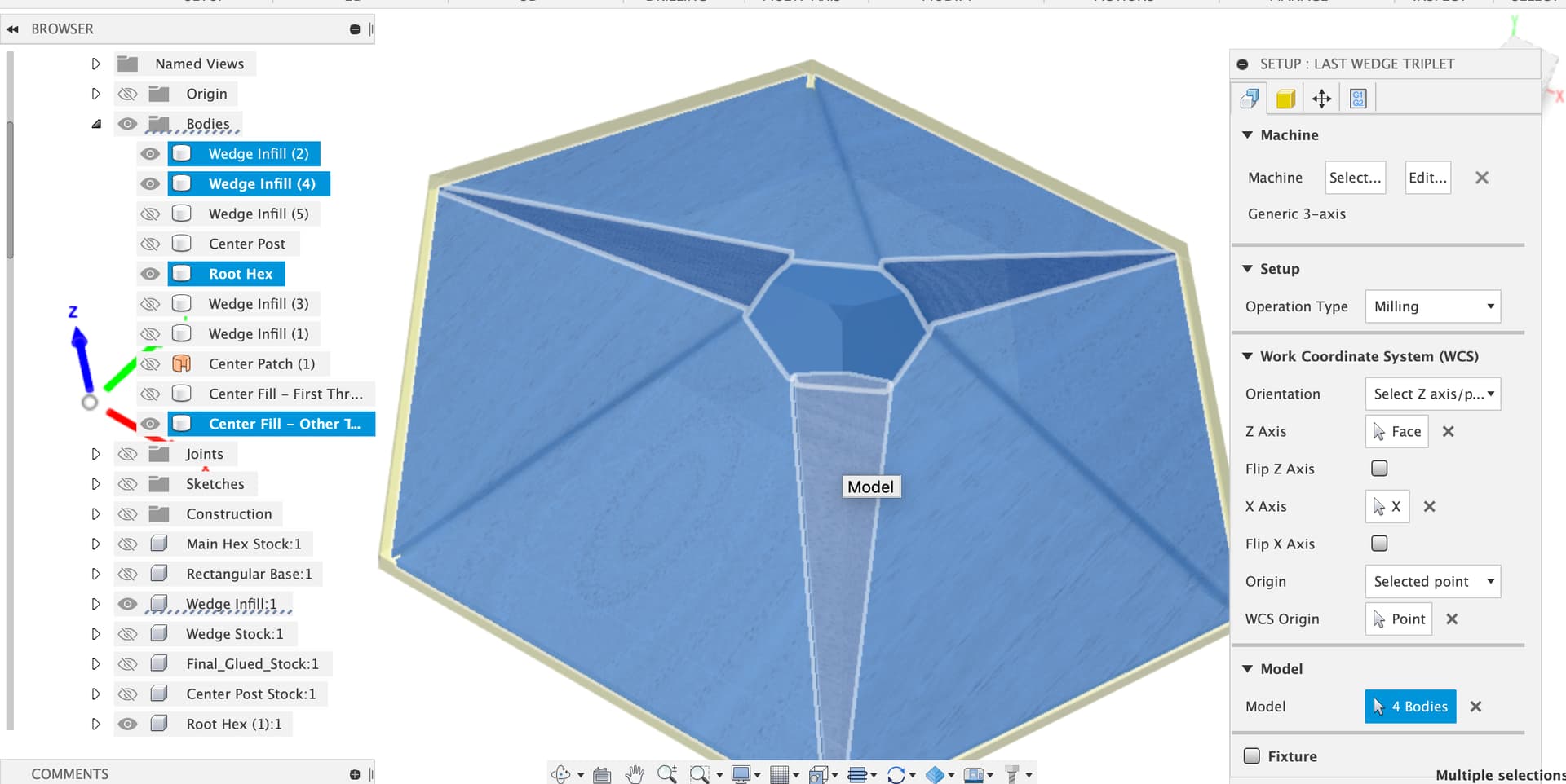
Recalculating the toolpaths seems to keep the adaptive clear out of the 3 wedges already glued in

And the 1/8" and 1/16" seem to leave them alone too
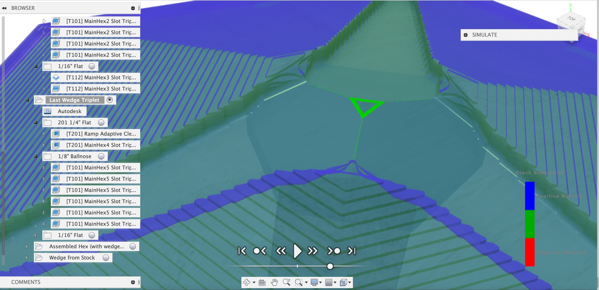
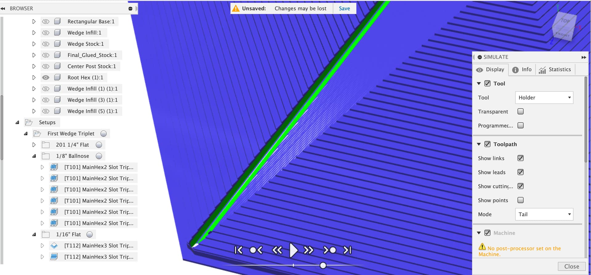
You can’t watch the simulation too carefully…
1 Like
Sanded. Well sanded, actually. I was wondering if I should try to modify the big ball cutter pass to not be so linear, but to instead go around the ramp, kind of like the adaptive clear. I think it’s better to have the cut lines go with the grain, but since I’m sanding them out anyway, it’s not a big deal.
I’ll try the addition to the model as you suggest. I was wondering what “Model” meant anyway, so now I know!
thanks!
1 Like
There’s three main tools in the 3D smart toolpaths to let us mess about with what is ‘Model’ and should not be cut away.
- Machining boundaries, just what they sound like, contact point is a subtle influence but important to get your head around
- Model, the 3D toolpaths use the model from the setup if you ignore this but in each toolpath you can either override completely what is model, or check the ‘include setup model’ box and add extra bodies as ‘model’ to force the toolpath to avoid them
- Avoid / Touch surface, another just what it sounds like, these are a good alternate where the machining boundaries don’t let you express the constraint well
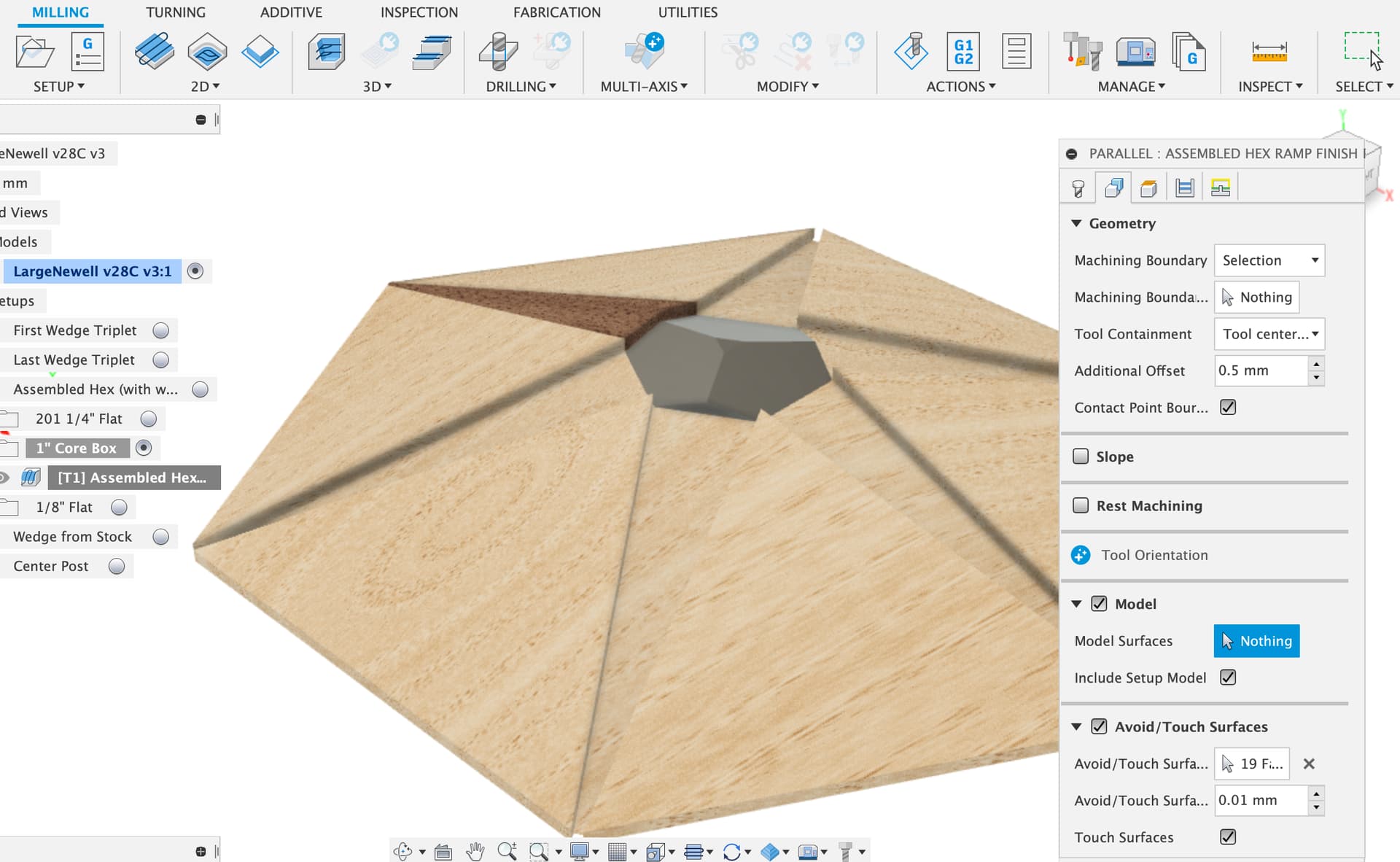
None of that smart stuff applies to the 2D toolpaths, they just cut wherever you told them to and will happily chew away at the model. That’s where setting the ‘comparison’ colorization in the stock part of toolpath simulation is great, that the blue & green view I normally use, blue is stock, green is part, red is your mistake.
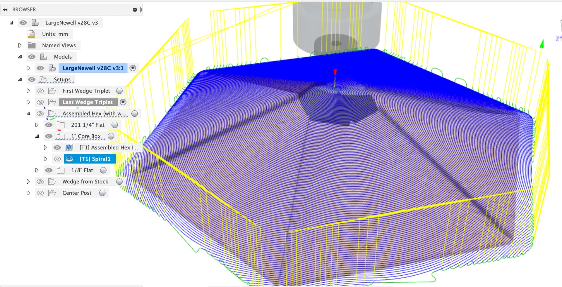
To try out different toolpaths with the ball cutter a good trick is to right click on the toolpath and select ‘create derived operation’, in this case I chose 3D / Spiral.
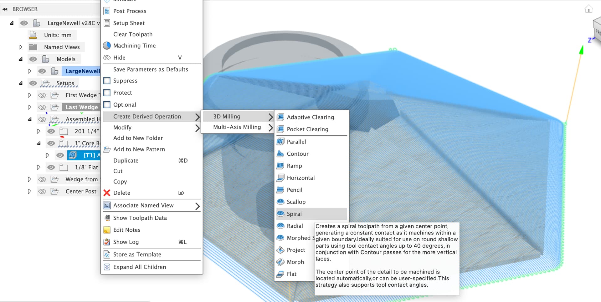
This keeps as much of the setup of the source operation as possible, tool, feeds, speeds, model selections, boundaries etc. etc. to save you setting up the whole operation again.
1 Like