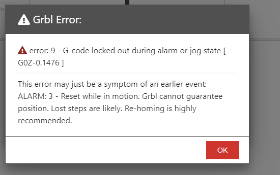
I’m enjoying learning to use carbide create for my 3d projects, but I am getting a little frustrated. At the end of this message I will add a couple of pictures at the end of this message of the end result. As well my gcode and an error I am consistently getting in openbuilds control.
So earlier in the week I was trying to follow a youtube video to make a spoon and was getting the same error message that I’ve attached here. When I was making the spoon I figured out that the retract height was too high so I adjusted it to 10mm and the error went away. As well, I am getting a pause on when it starts. So starts, pauses and I have to hit start again. My understanding is that G04 is the pause command, but I do not have it in the code. Oh, by the way, I’m using a Fox Alien Masuter Pro, 400x800.
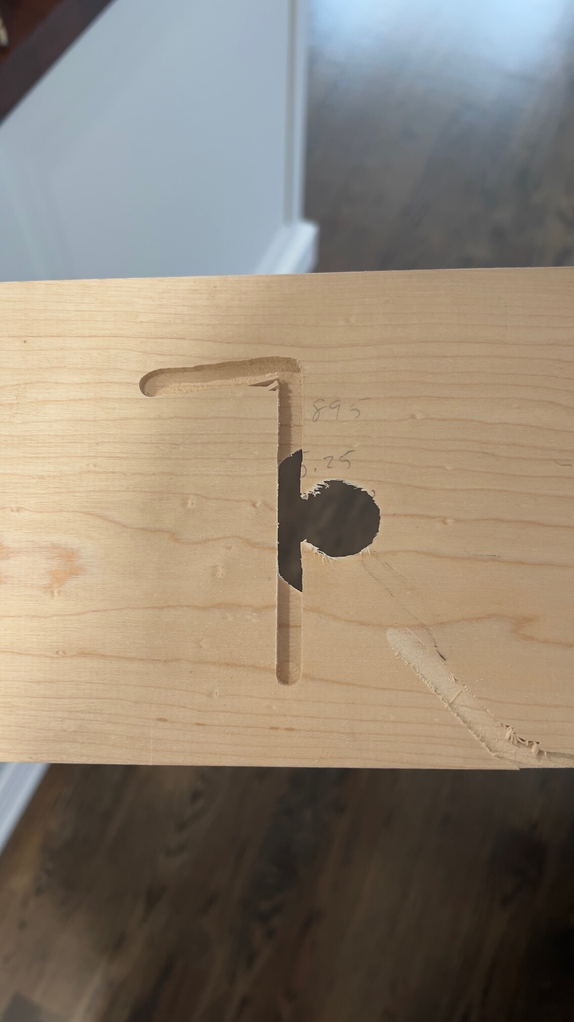
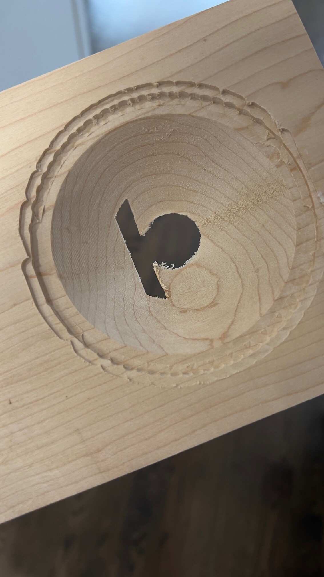
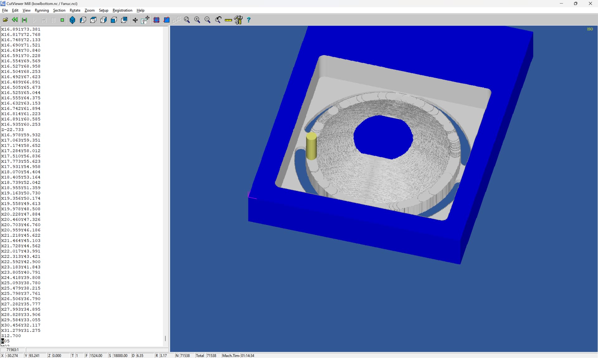
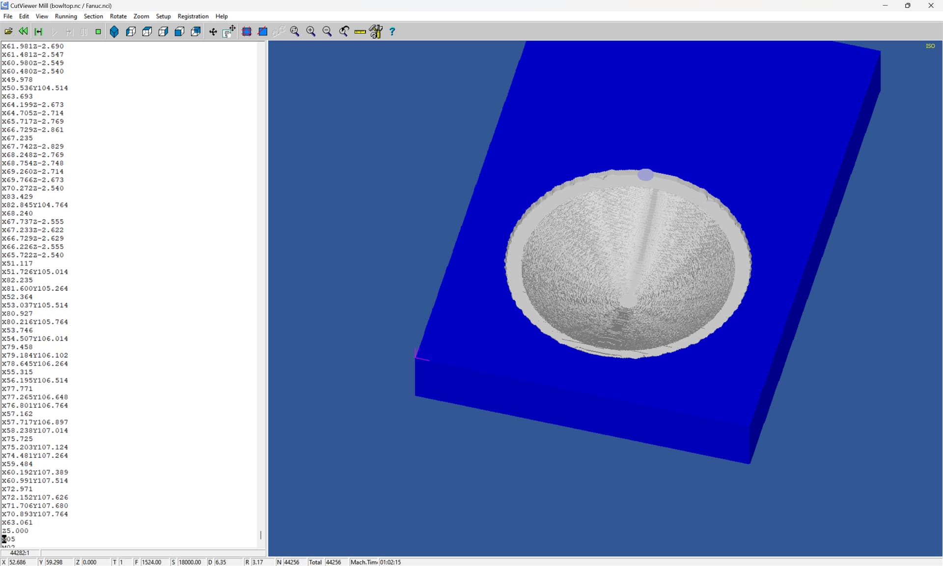
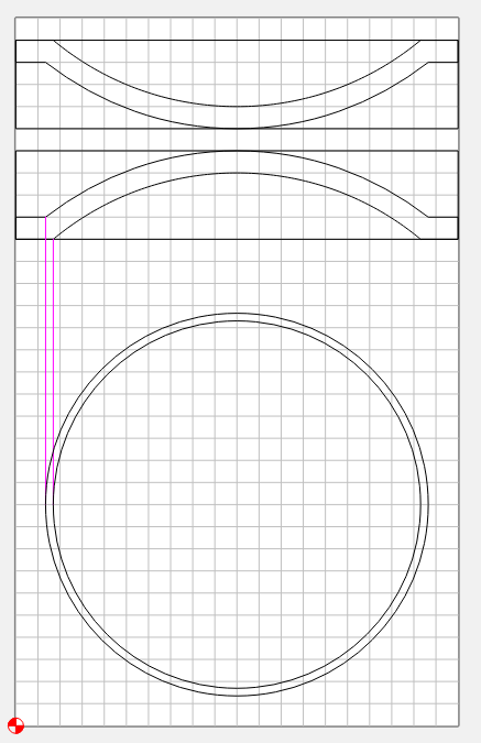
Then I created a bowl where I had to carve both sides. I’ve attached the code for bowl top and bowl bottom. Although initially it went wonky on the first run, I stopped it, repositioned the bit and then it ran fine. Only issue I had was I made the depth exactly the same as the stock so it ran through the material, but with accuracy. It didn’t penetrate the spoil board. So the carve went well. Then I turned it over. Re-positioned the bit and everything went haywire. Getting the alarm, hit start again and then it plunges into the wood too deep. The first run was to clear out a pocket, but it went near the middle of the piece and gouged really deep.
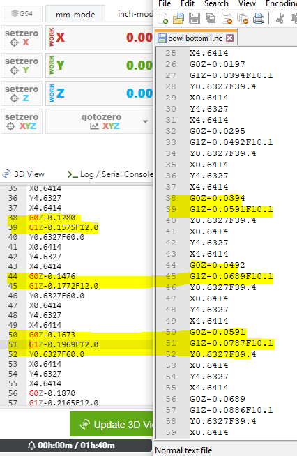
As well when I look at the code for the bowl bottom and compare them in openbuilds control and notepad++ where I seem to be getting the first error is at line 51. But then I noticed the code was different in notepad++. I’ve highlighted a few that are not the same. Big question?? Why is that different?
If someone has time to review design and the code I would greatly appreciate any advice you have to improve this situation.
Post the .c2d files and let us know step-by-step how you secure your stock (and the cut part for the flip) and set zero relative to it and manage all tool changes.
I’m not sure, but this doesn’t help when everything seems to work okay with my cnc using other software like easel, aspire or vcarve. Easel doesn’t have the design capabilities and Aspire is totally overpriced for what I am doing. There isn’t much of a learning curve with your software which is very appealing, but if it I can’t use it to carve what I create, it isn’t much use to me.
Are you saying that if you set up an identical project with the same feeds and speeds, that it will work using Easel or Aspire, but won’t cut correctly using Carbide Create?
It might be worth making a known good file with boxes that have different known depths and run on your machine in scrap material to make sure that what’s designed and called out is what the machine does.
Maybe 4 squares that are 1 inch by 1 inch and each box with a .125 inch increment or something similar.
Yes, that’s exactly what I am saying. I can’t design in easel, but can import an stl and setup the model to cut. I take the recommended settings like 1015.5mm/min feed rate with a 228.6mm/min plunge rate. Runs at 10000rpm which is my max on a 300w spindle. I can run it directly in Easel or export the gcode and run in openbuilds.
In Aspire, I designed one this morning and ran it just the top side and exported it to gcode with the same settings as I use in easel and no problems. I don’t get a pause or error like I do in Carbide. One observation is that when I run it through easel, it walks you through the steps before you have to carve. When you hit carve, it raises the bit up, moves to position and then starts the carve. Aspire does the same thing. In carbide create, I set the bit to the bottom left corner and if it is on the wood, when I run the carve, it doesn’t rise up to travel. It literally starts carving into the wood from that position.
I’m not dogging the program. I believe there is a lot of potential upside to your software. I just need to figure out why it’s doing what it is.
I’ll try the test file you provided and see what it will do.
Just a follow-up on a 2d model. I already know this will work as I have created similar files and have carved them without an issue designing in carbide and exporting to g-code. The issue is when I do 3d. Do you have a 3d file that I can try?
On a first test run I had the feed rate low at 500mm/min. The nice thing in openbuilds you can have a set speed of 1000mm/min with the option of using a slider to adjust the speed. So before I begin, I slide it down to 500mm/min and slowly bring it up.
I worked through some of the confusing issues. I created a simple file created on one pc and opened the same file on another PC. Even though both pc’s were setup in units of mm, one was saving the gcode in mm and the other was saving it in inches. Not sure why you would create mm for projects, but when saving g-code, in the post processor there is a selection for inches and mm. Must be a reason.
Speaking of that, shouldn’t there be a general toggle between inches and mm on every page. Personally I use both. As well, could you not program the system so that when you set the project measurements it also sets it in the post processor or is there a specific reason why it’s not a good idea? That isn’t the reason why it was going haywire.
I investigated further and reviewing the g-code, it seems that in the beginning of the code you are anticipating a tool change.
The program generates and saves the following:
M05 - Stop Spindle
M0 ;T201 Unconditional Stop - Tool Change
When I start the job, I immediately get an alarm, the job stops (not pause). After clearing the alarm, I hit start again and it thinks it needs to move to the location again. That’s when it goes haywire.
I removed the two lines of code and it works now without any issue. Are these two lines meant for your machines specifically or any machine that runs g-code? Just adds additional steps to the workflow.
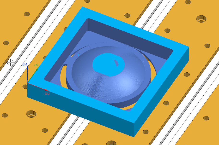
That’s NX (Unigraphics). I made a post & simulation for my HDM & I can pull in external programs & simulate them with material removal. I still have to create matching tools & workpiece for what’s in the G-code.
Might be a bit too advanced for me but will give it a try. Oh by the way further to my other message, the reason I believe it plunged too deep was my user error. Going between inches and mm, I may have been on inches all the while thinking it was mm, so yes, probably they reason for the gouging. I wish CC had a measurement toggle on each page.
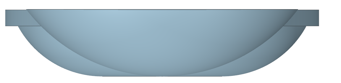
Without true double sided visualization in CC, I’m trying to wrap my head around cutting the bowl to equal thickness on the inner and outer arcs. Any suggestions would be more than appreciated.