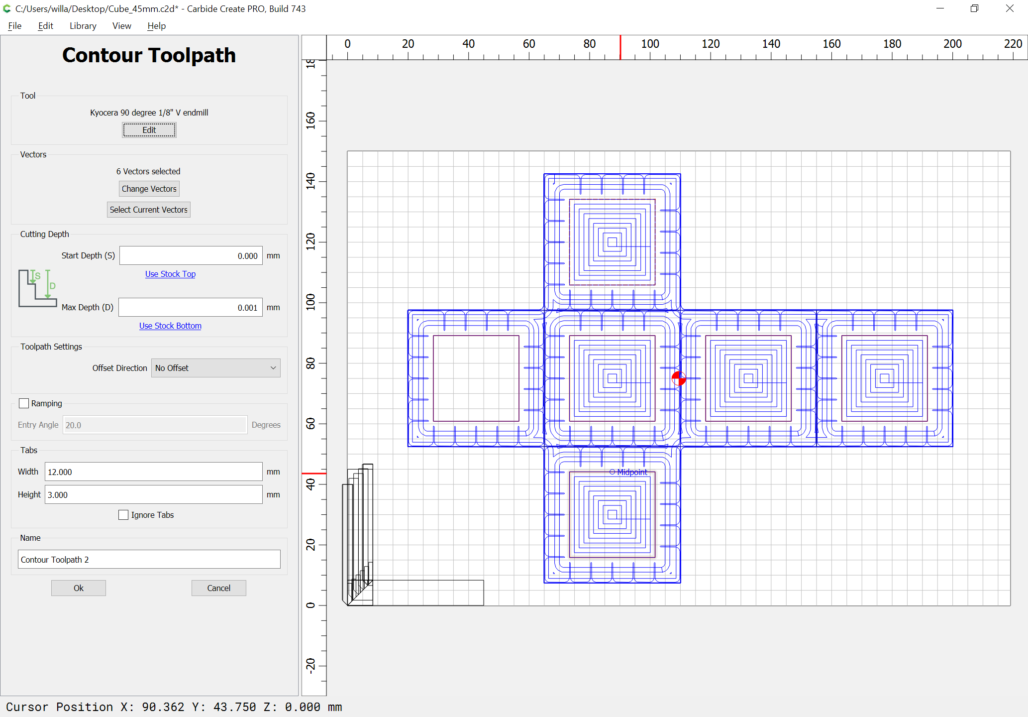
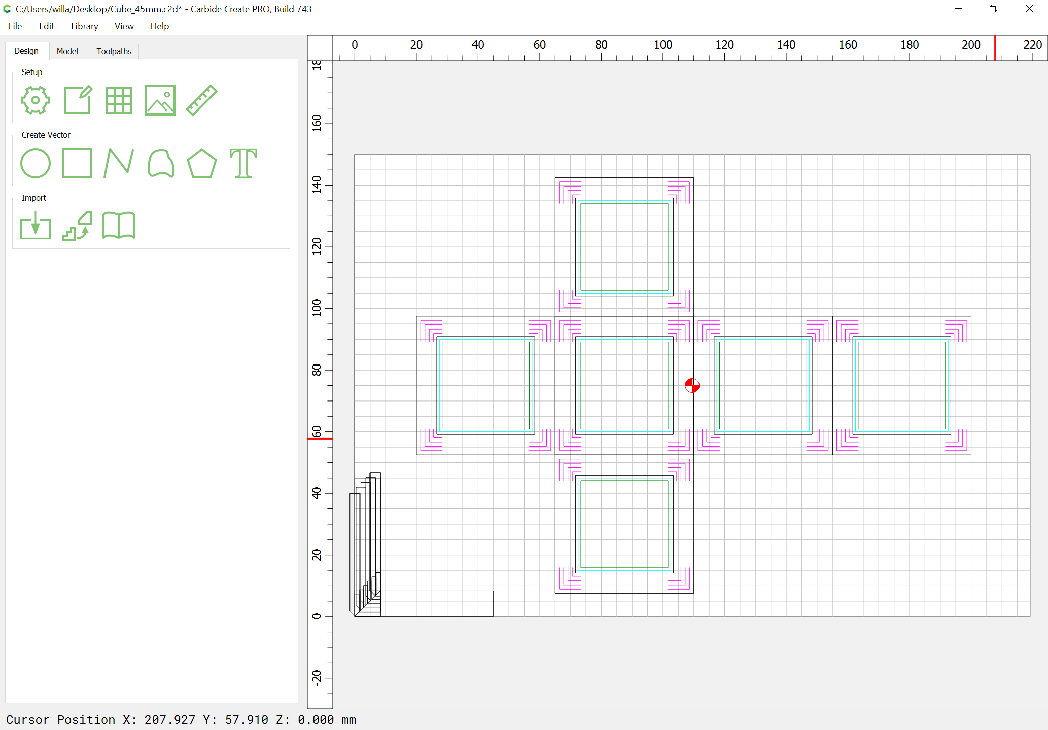
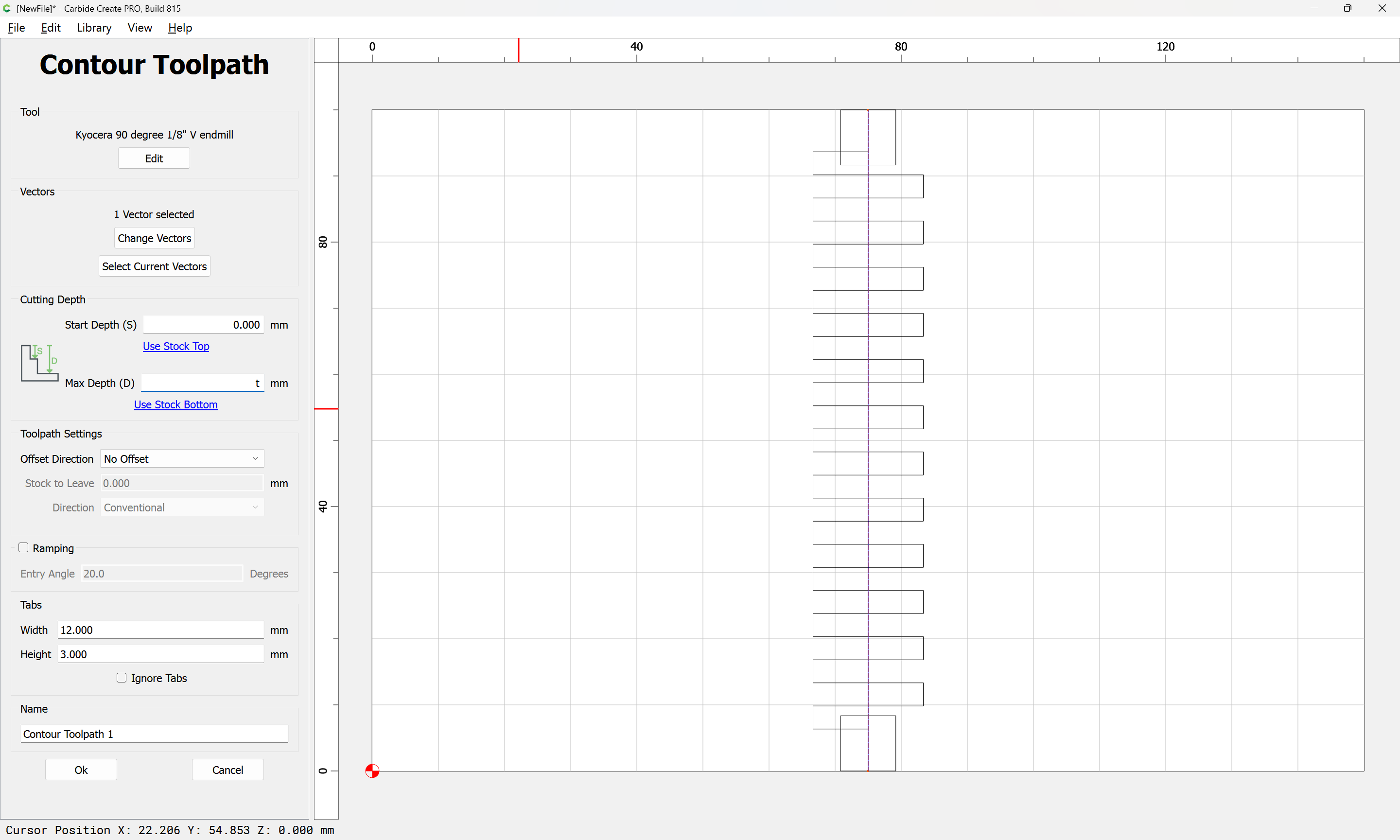
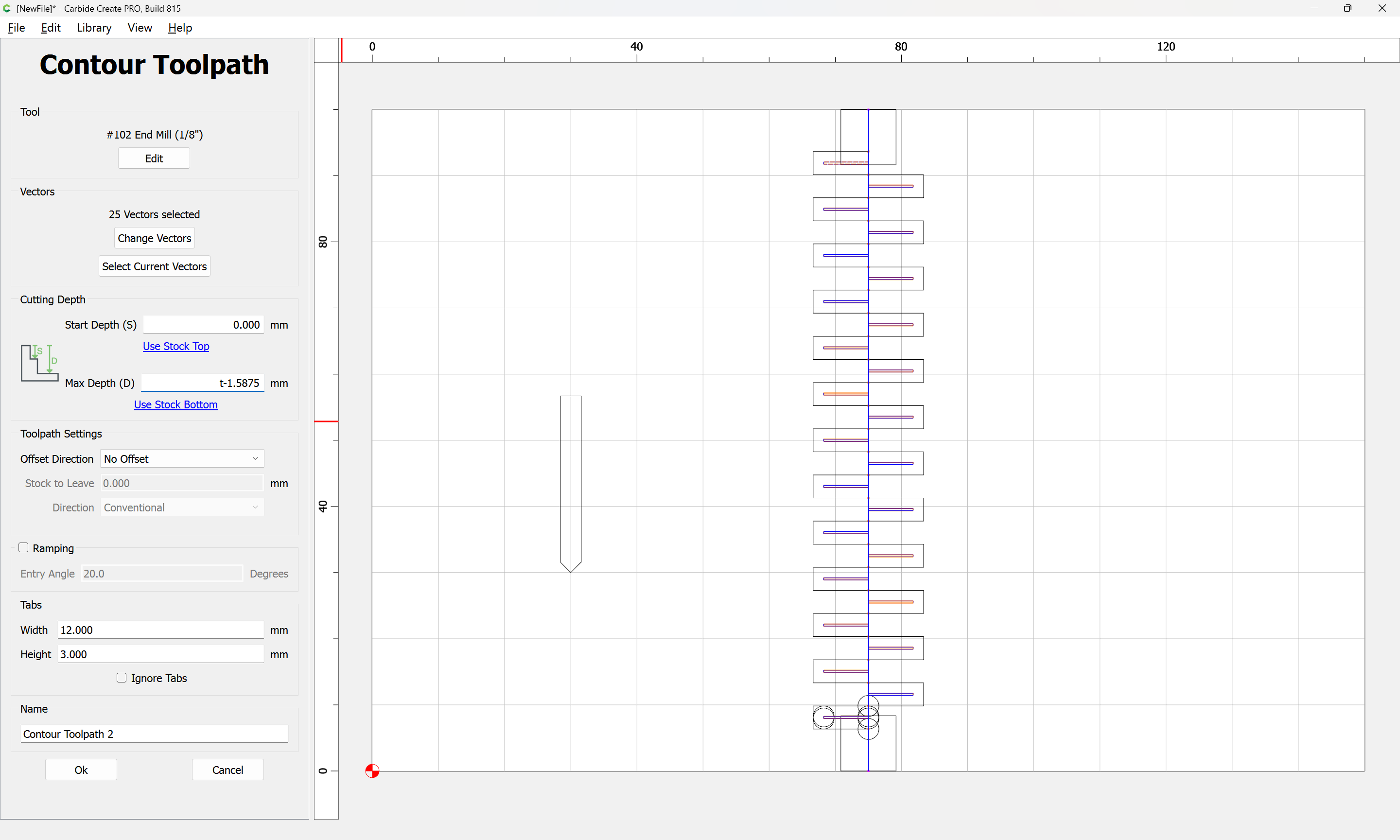
The bottoms of each may then be measured to determine the offset from the edge/top of stock, but the first thing which should happen is drawing in rectangles which are inset by stock thickness from the face rectangles and assigning a no-offset Contour toolpath to them at the top of the stock (well, 0.001mm below the top of stock — it’s not possible to assign a depth of zero to a toolpath):
This covers the case of the stock being thicker than expected.
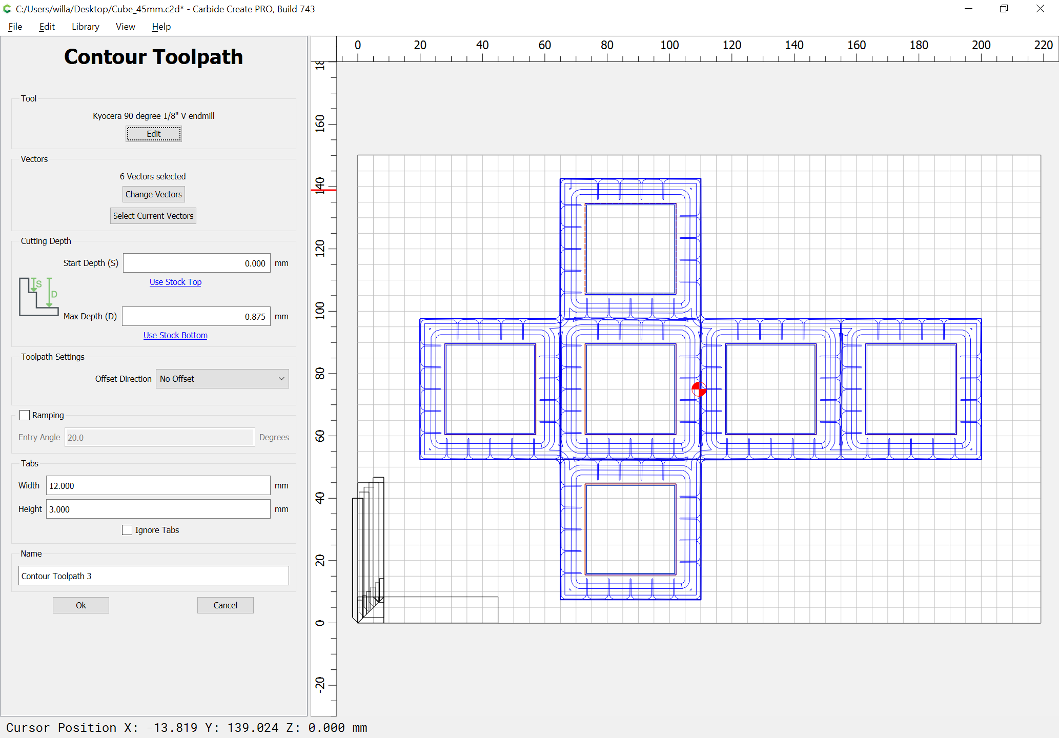
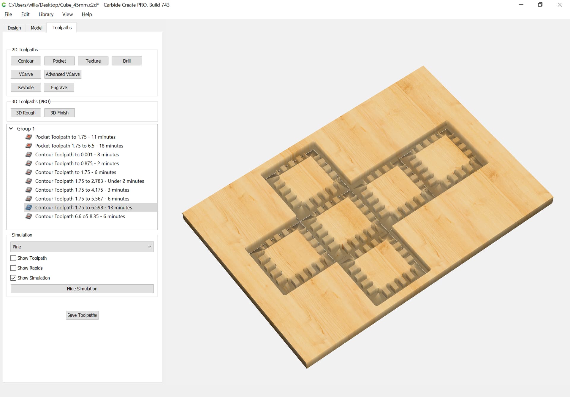
The next two V contour toolpaths continue this, working down by first one quarter the distance, then to half the depth of the endmill diameter plus 10%:
and reviewing the above as well as the various linked projects and other efforts, some thoughts/considerations:
the new OpenPythonSCAD and the ability of gcodepreview to output open geometry in DXF works — if one opens in LibreCAD first and re-saves as SVG
directly tracing the tool outline where appropriate is simpler to calculate since one can just use a command which includes outputting the DXF code in addition to making the cut
where appropriate, one can always use a separate command to create arbitrary closed geometry which matches some aspect of a cut
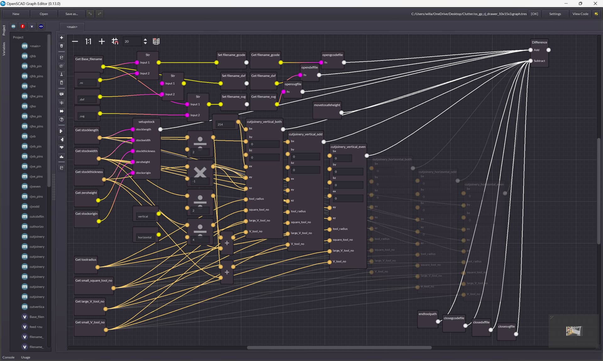
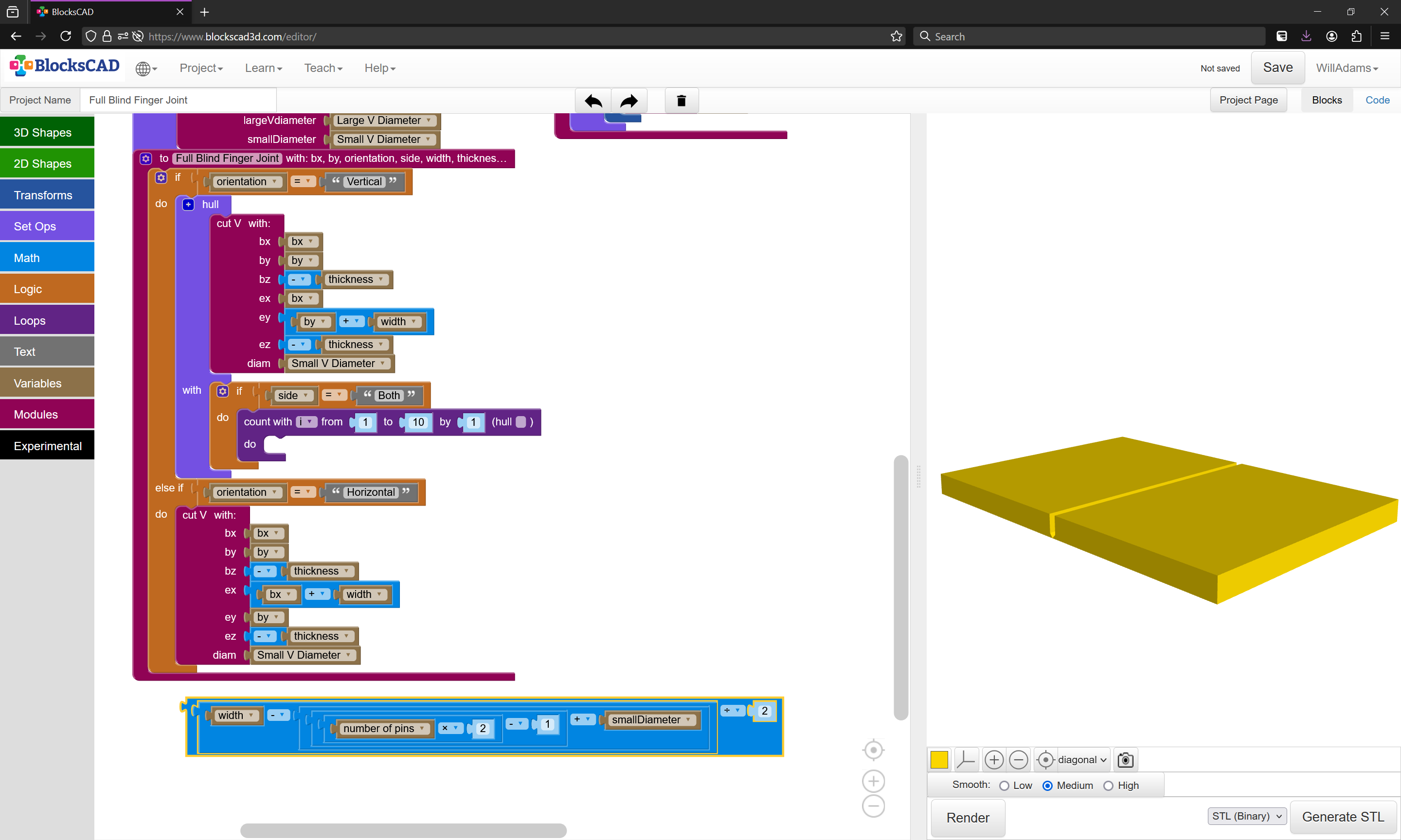
it is easier to block out prototypes in BlockSCAD than it is to create finished designs in OpenSCAD Graph Editor — most likely because of the difficulty of repurposing chunks of code and ensuring that slight variations in code have differences in appearance which are suitably expressive — this probably warrants further experimentation
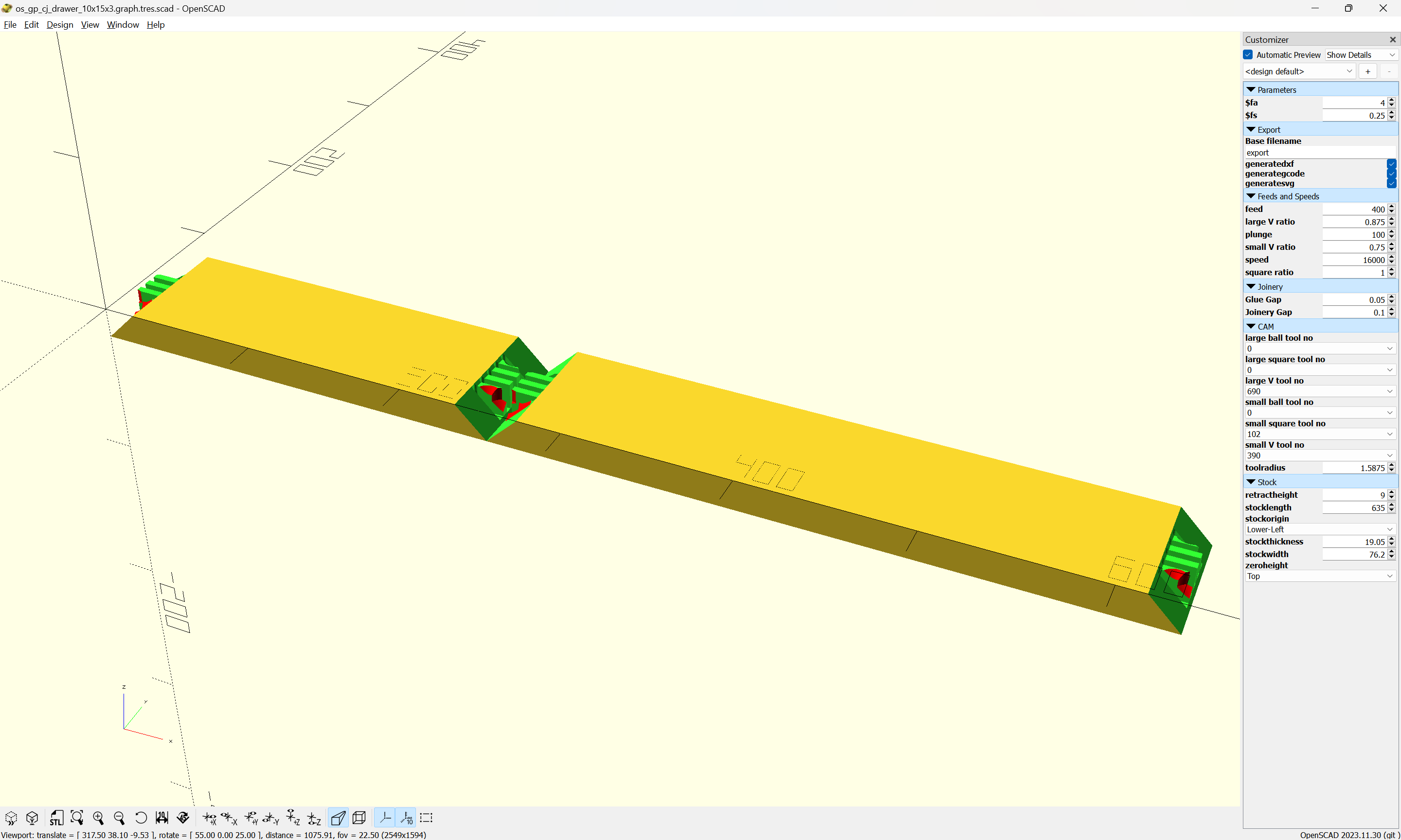
using 3 tools seems to be the best mix of ease-of-use and capabilities:
large V — note that if the library is set up to do this in one pass this will bound the maximum possible Stock Thickness — setting it to always make two passes seems expedient
small V — this needs to be a reasonable dimension, sufficiently smaller than the Stock Thickness that it will allow a reasonable size of Box Joint to be cut
small square — if doing this in a graphical tool it may be helpful to use a smaller diameter than the Small V (3mm vs. 3.175mm is one dimension pair which I considered and sourced tooling for), but if one is directly modeling toolpaths, having a direct correspondence is more straight-forward
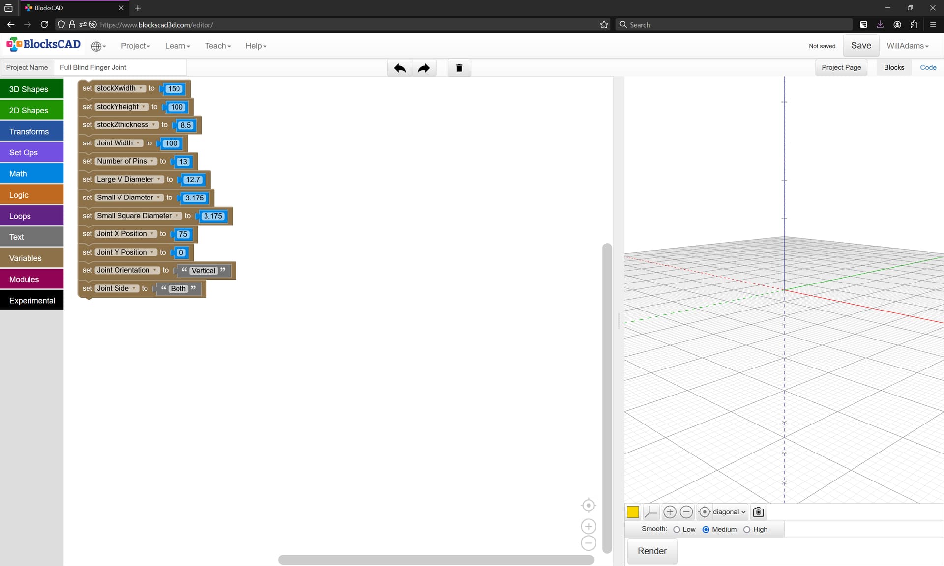
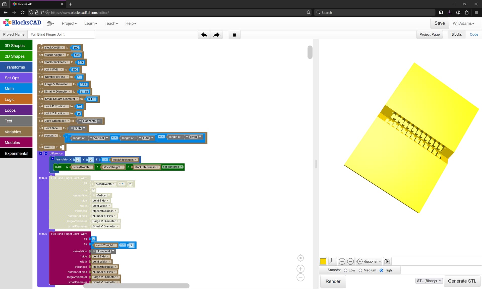
Starting by roughing out the design in BlockSCAD we have a pretty standard set of parameters to begin:
Note that it will be possible to position a joint both in terms of XY and in orientation and to specify which side of a joint is to be modeled/cut, allowing arbitrary part orientation.
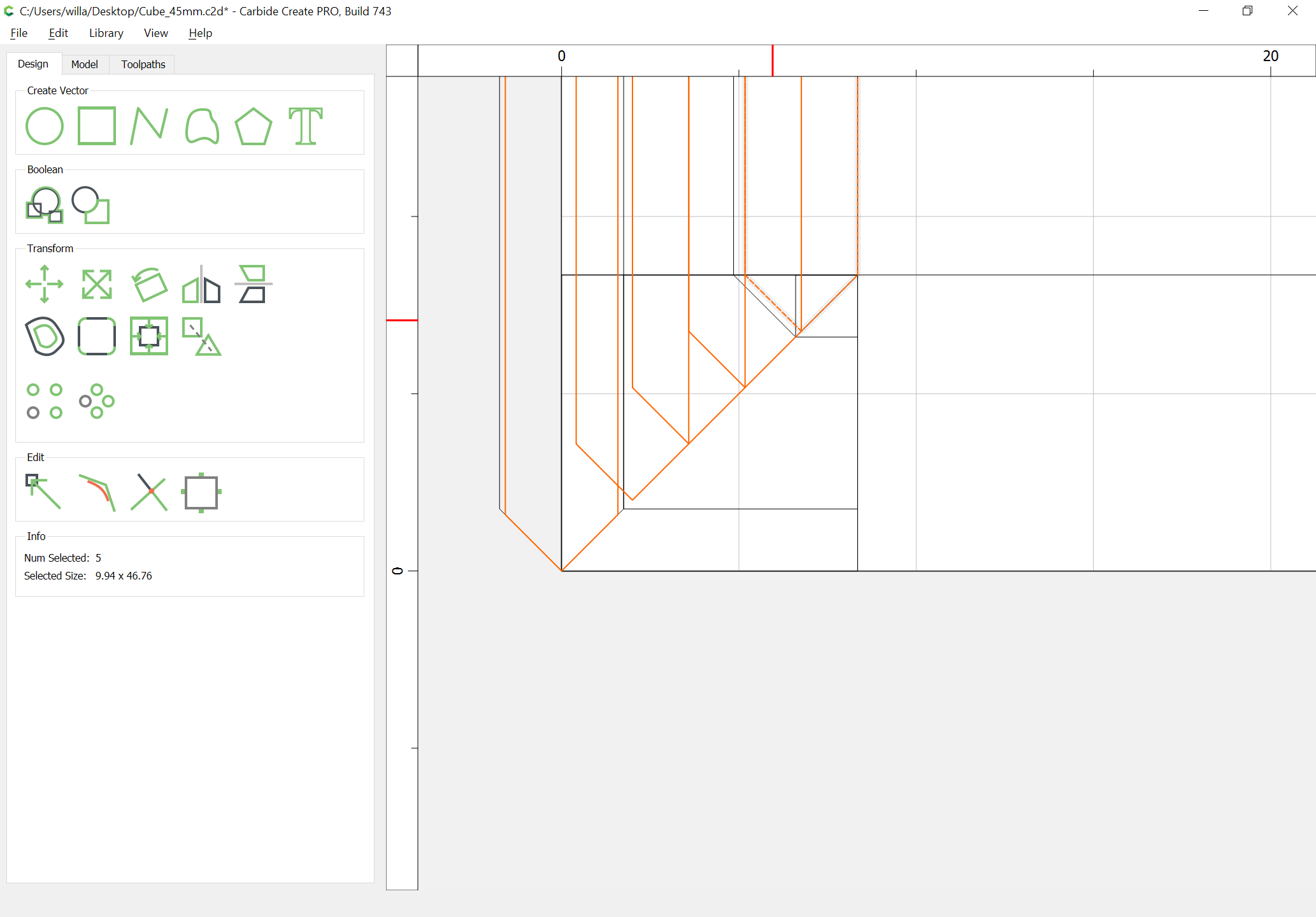
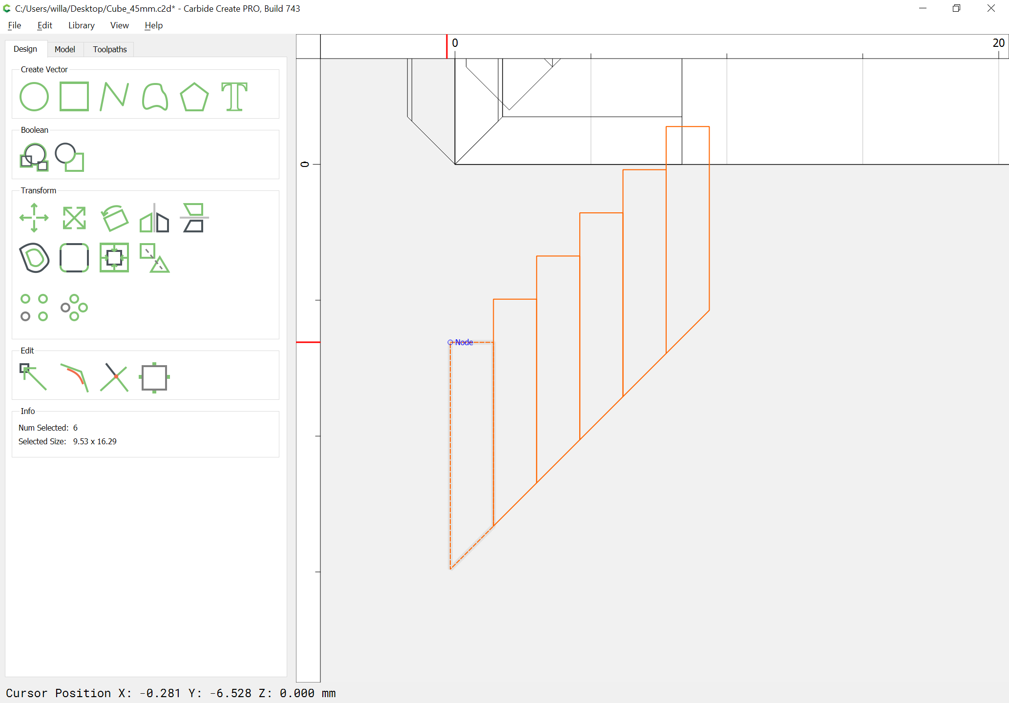
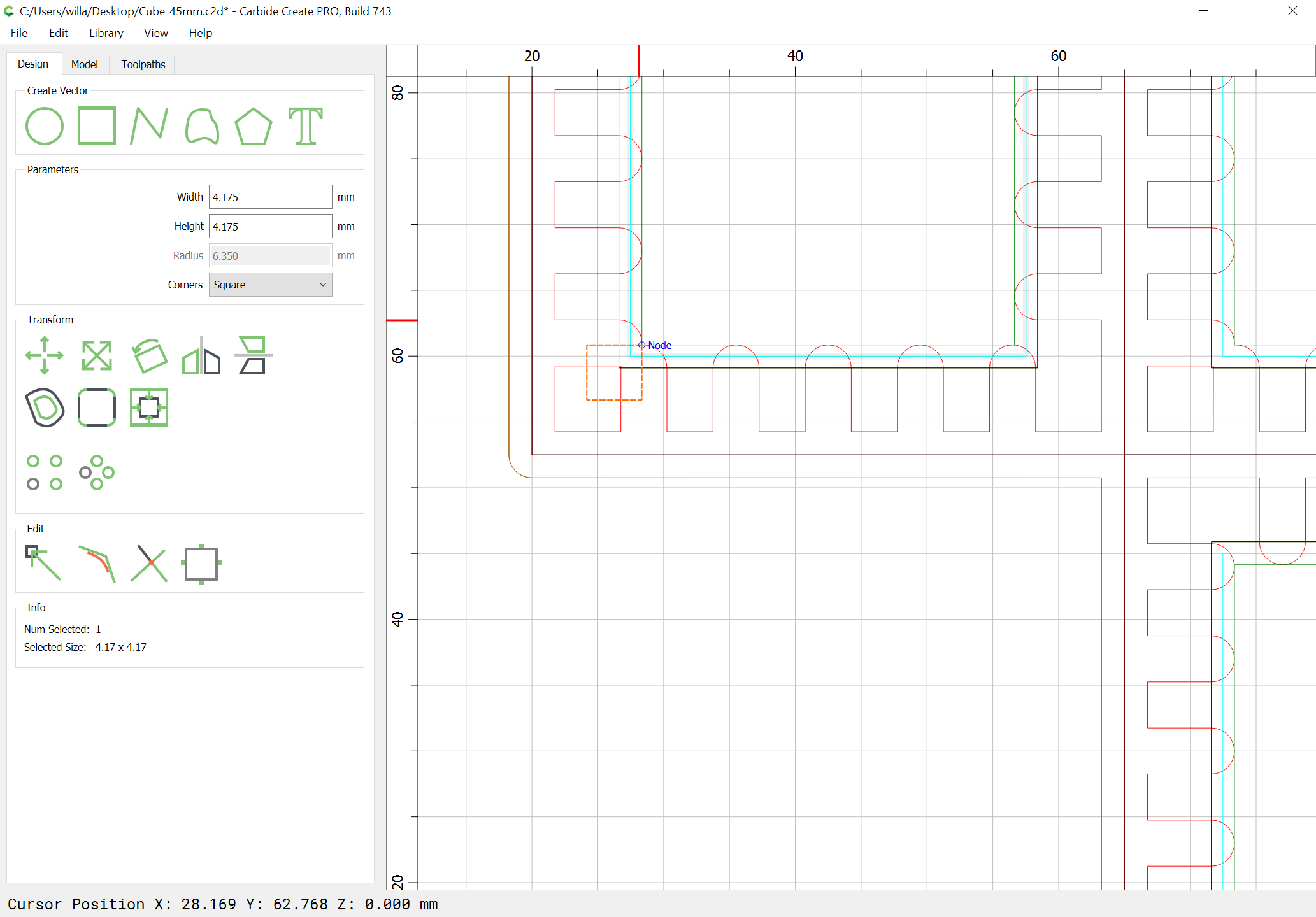
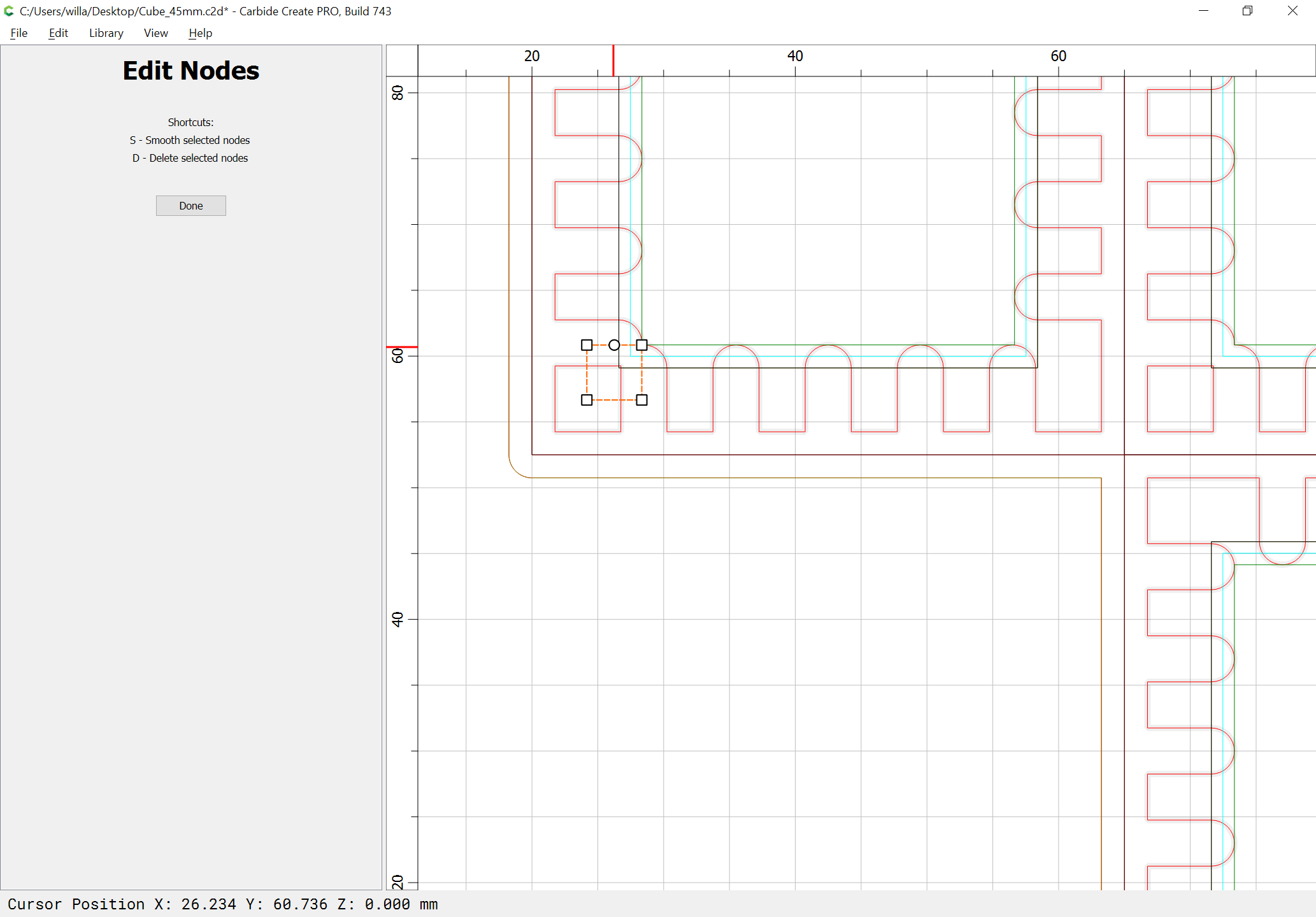
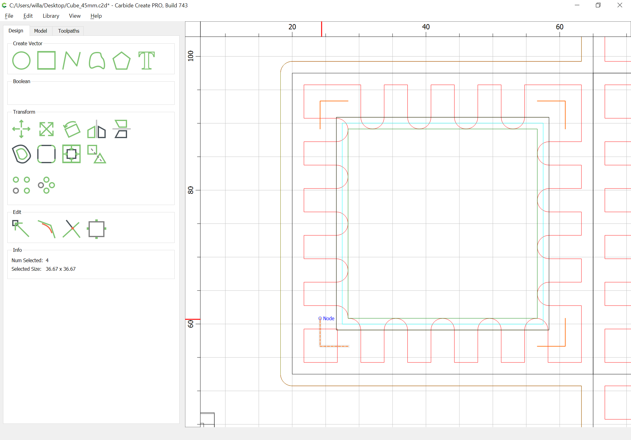
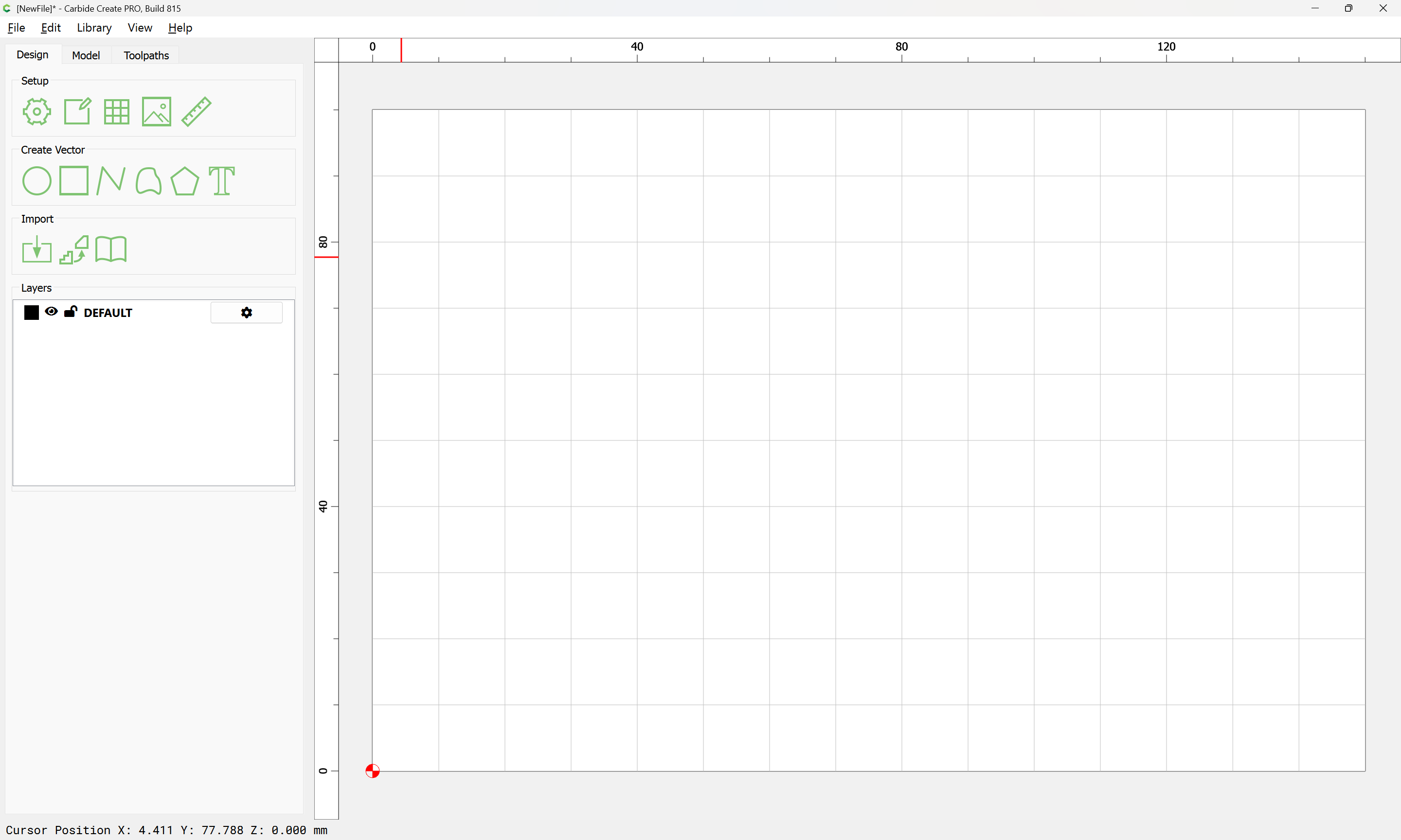
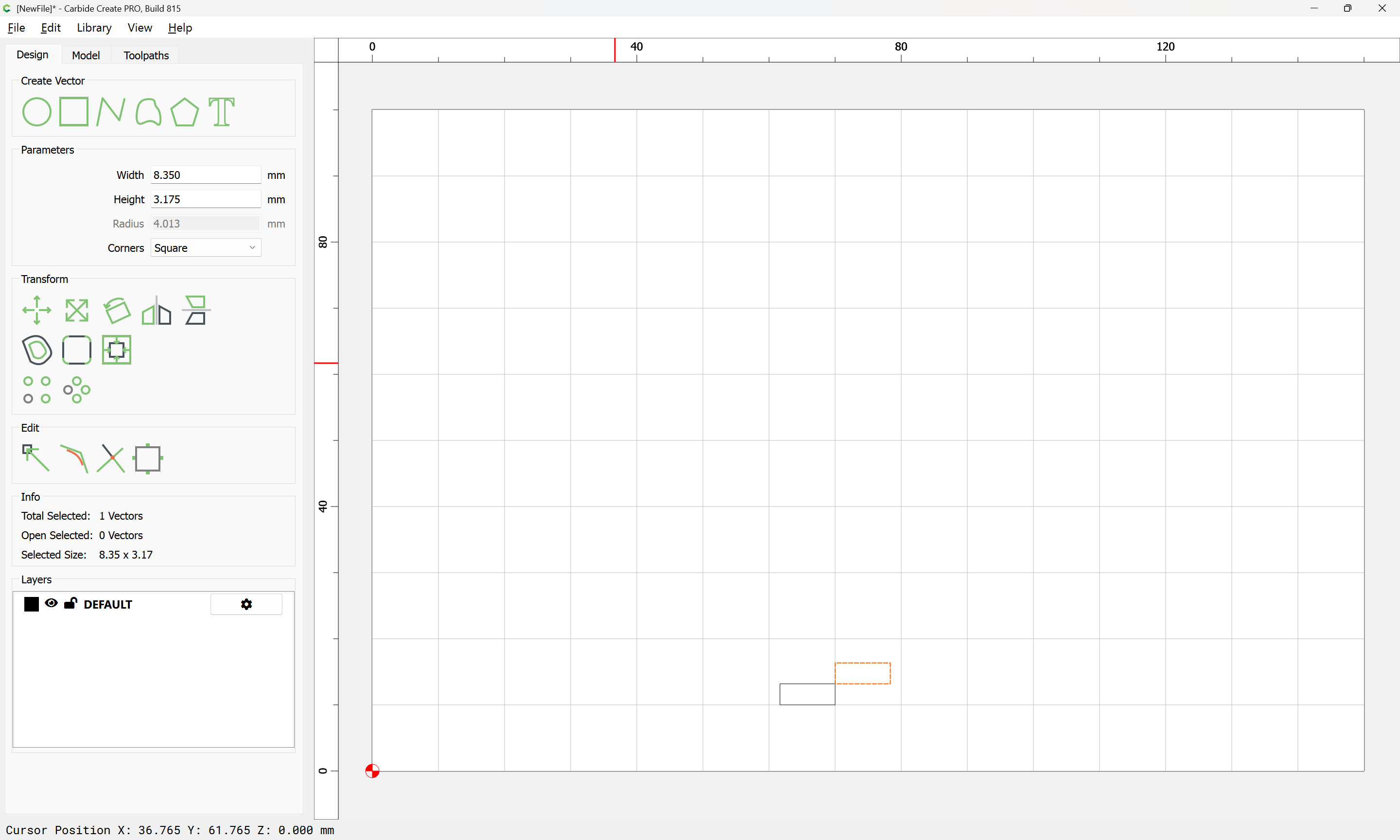
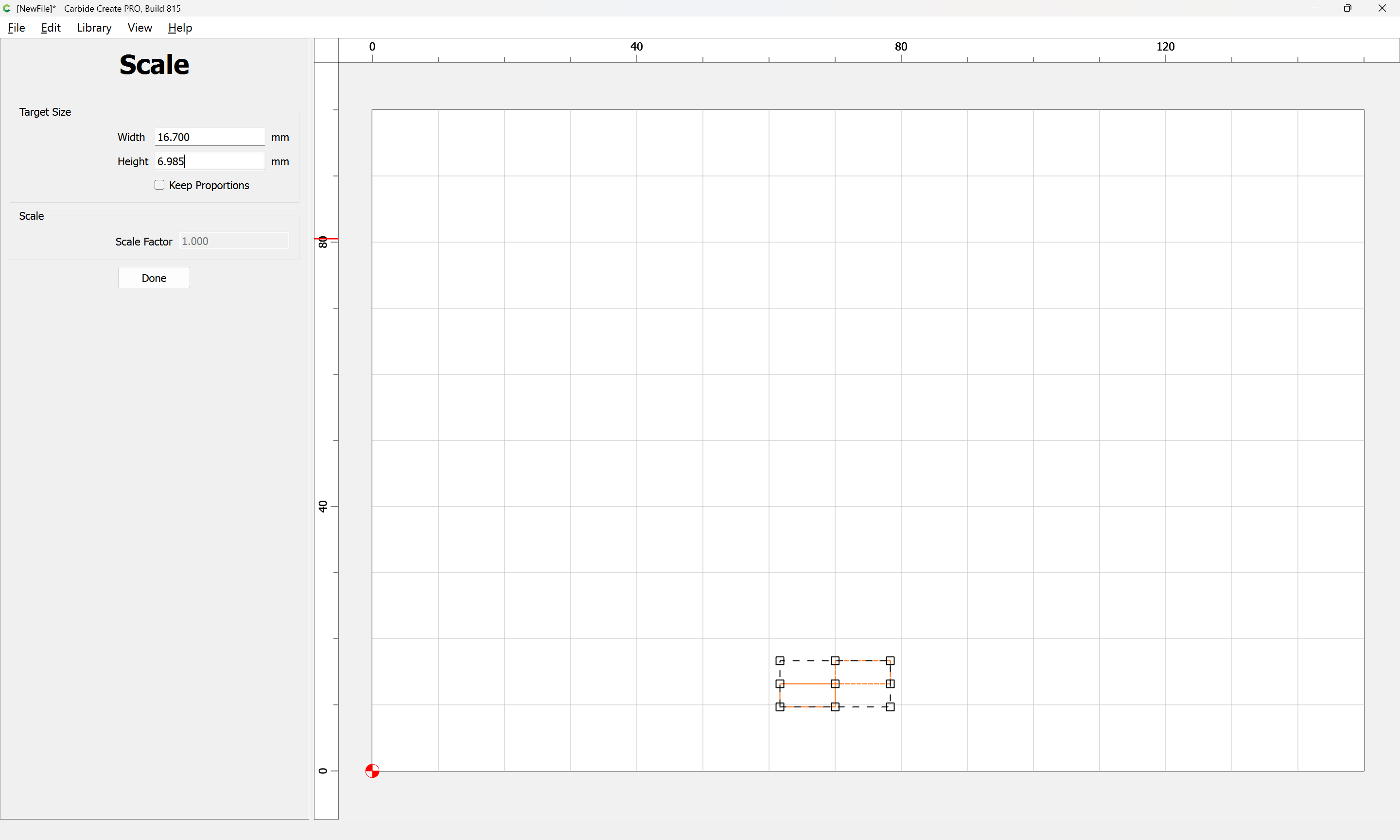
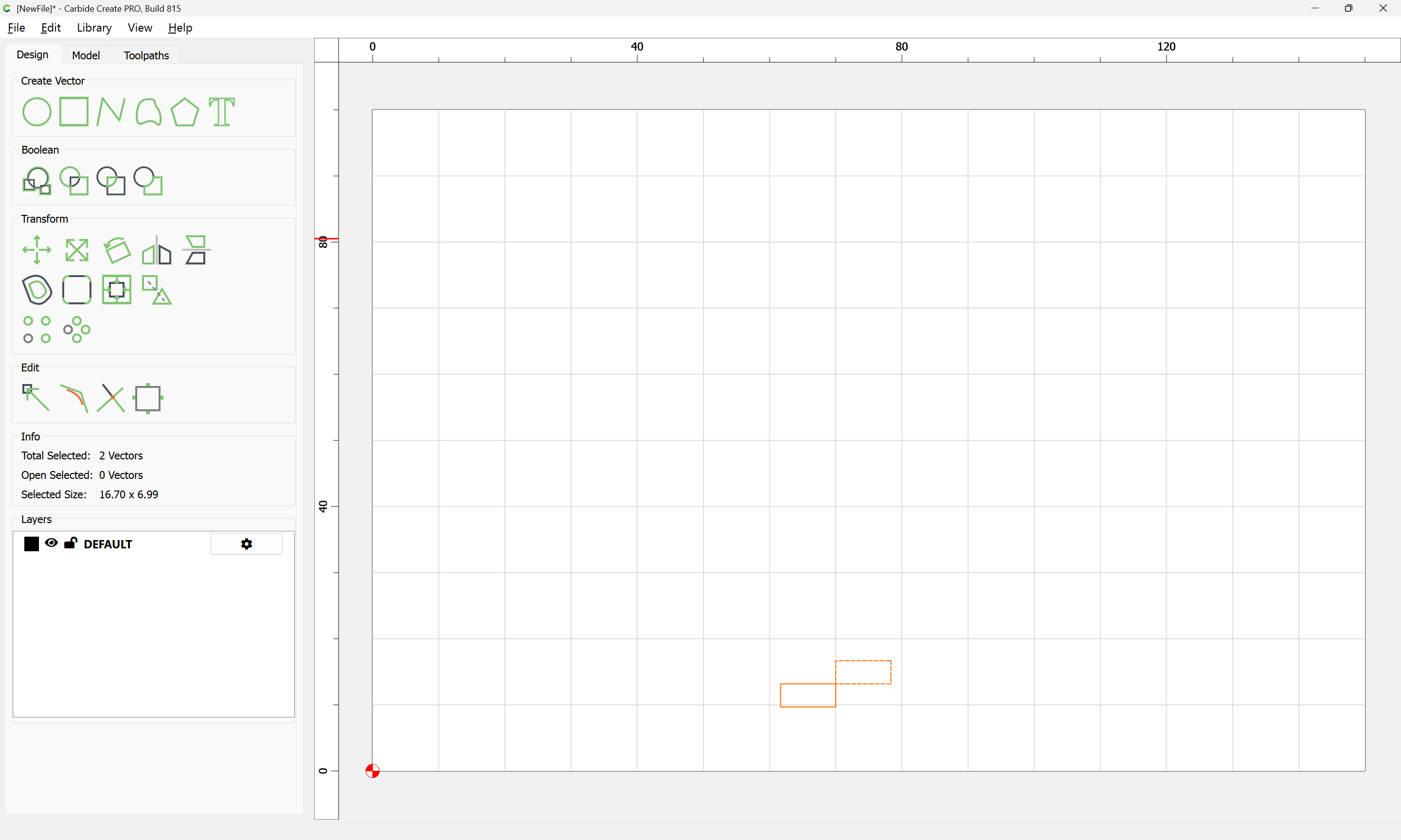
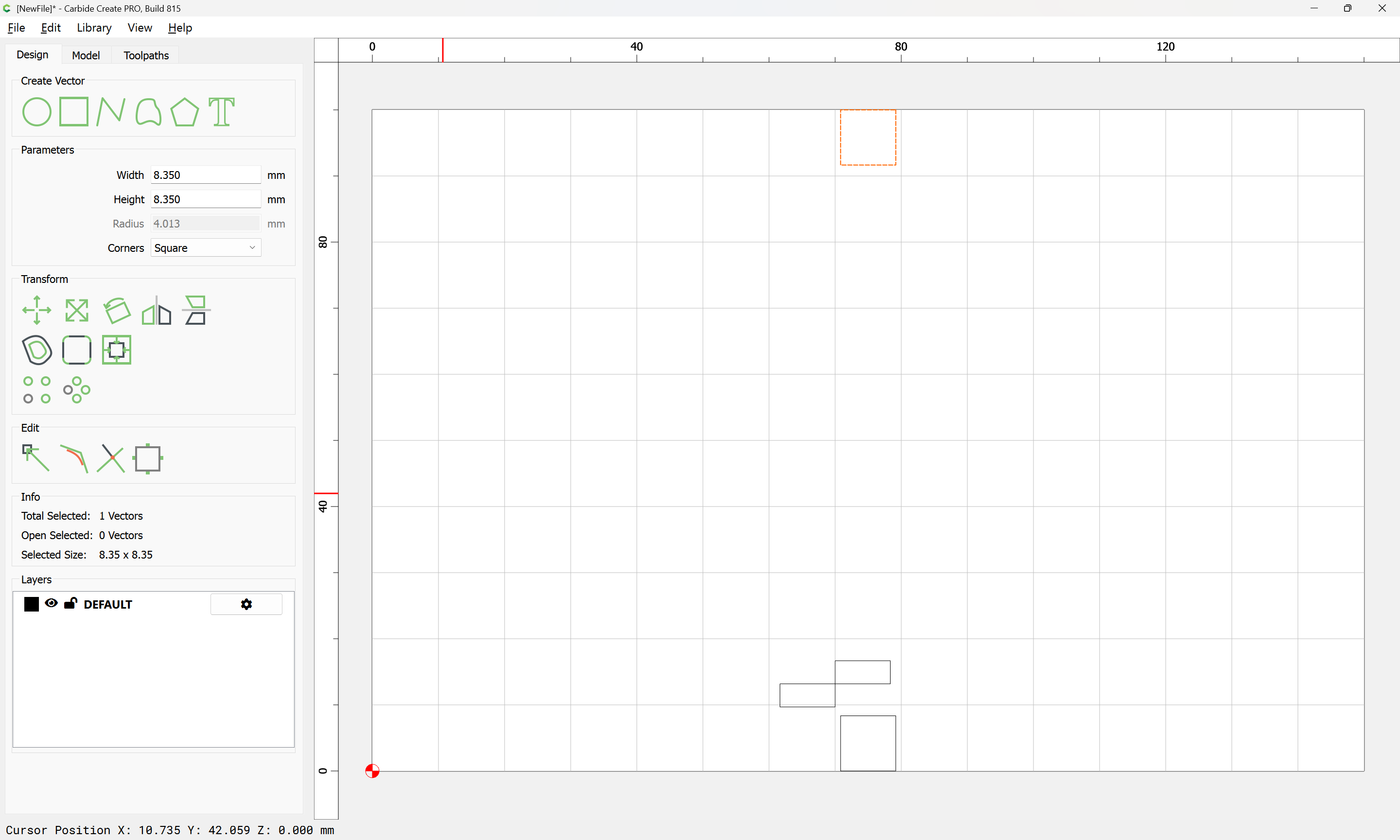
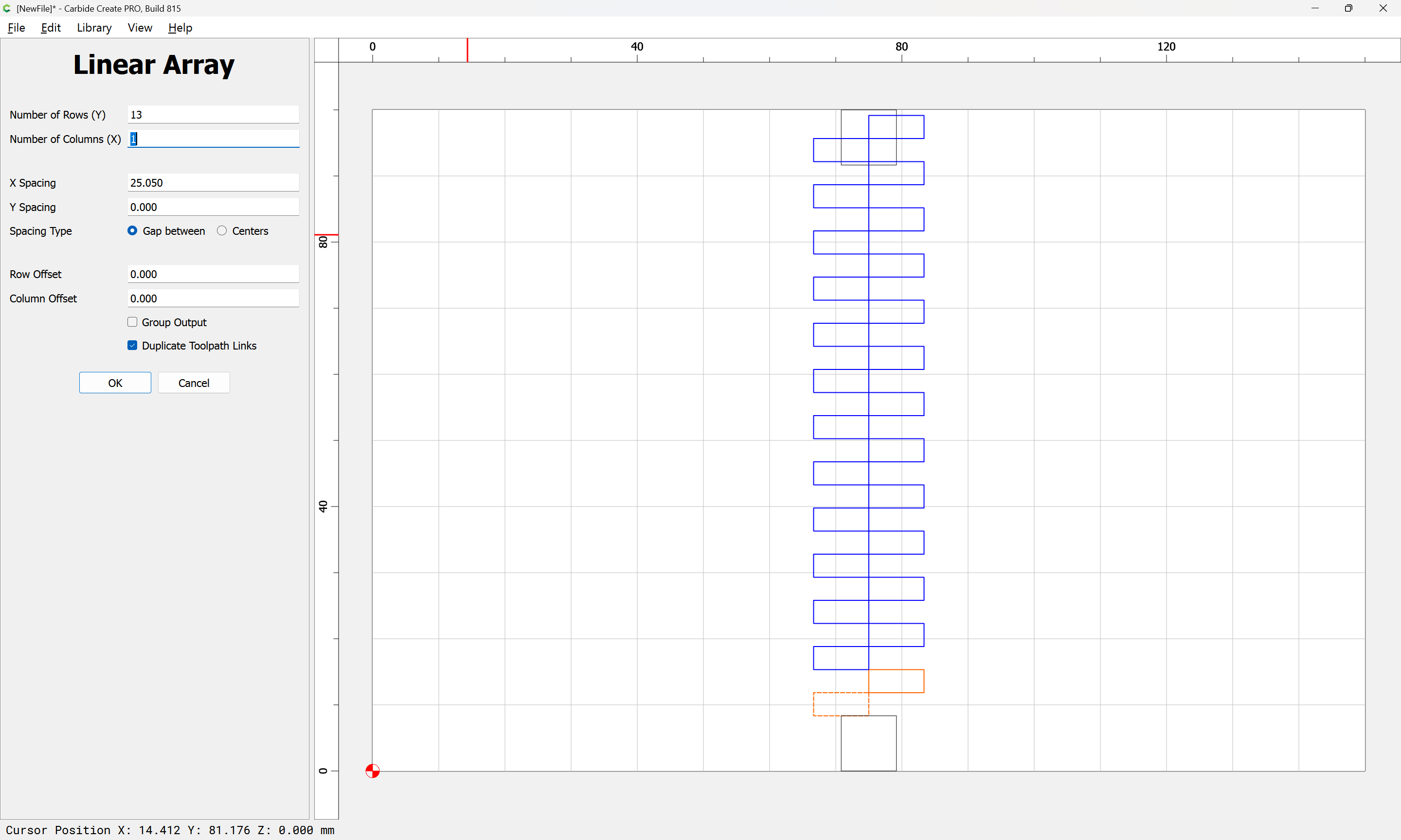
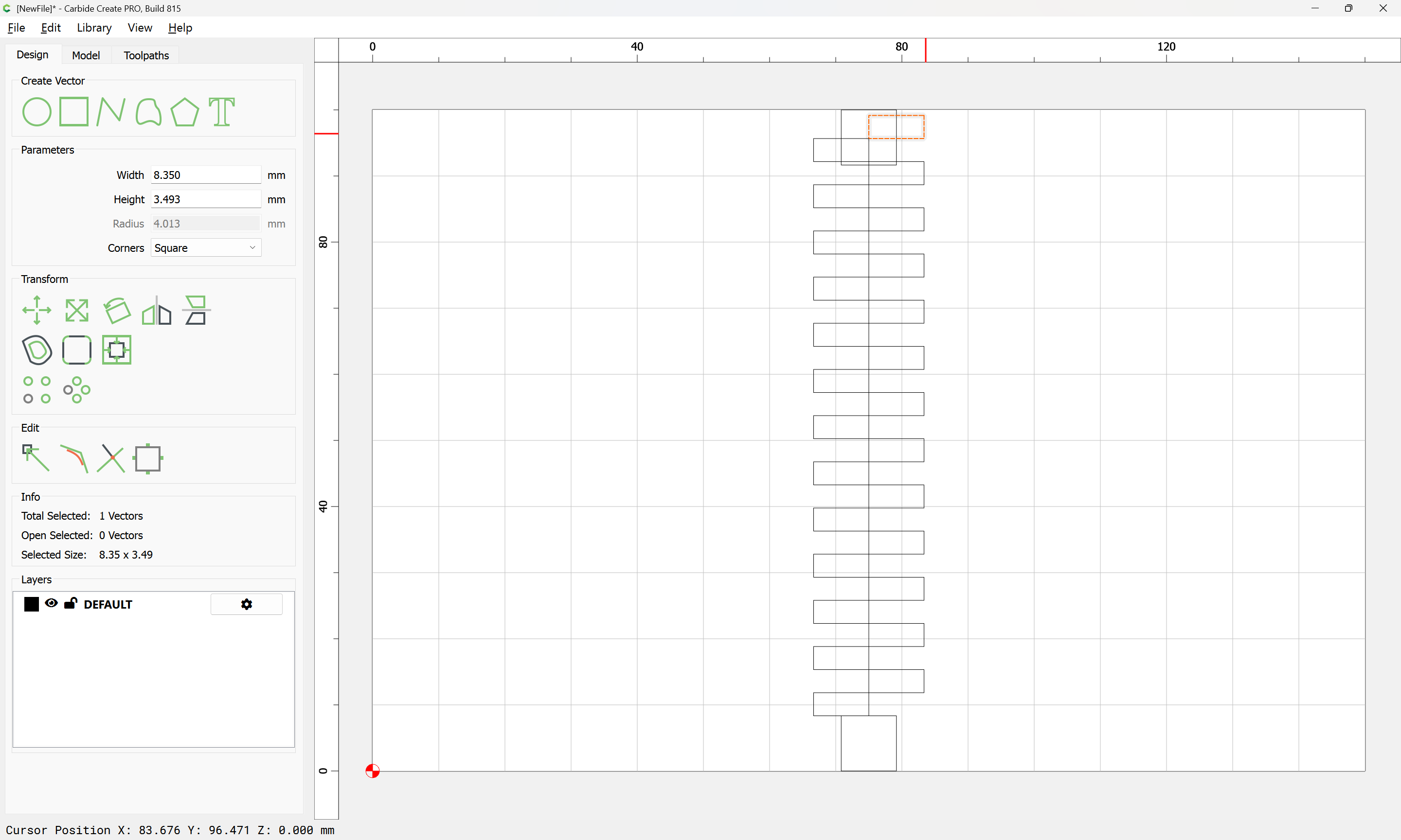
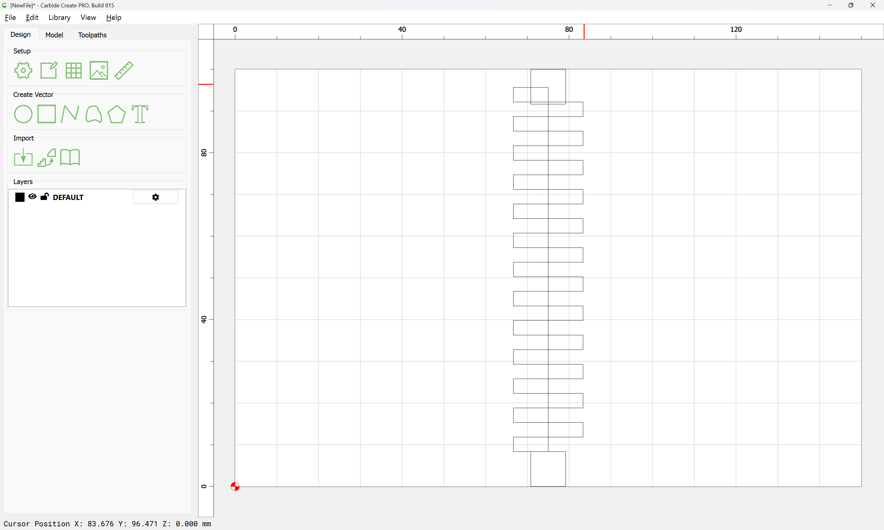
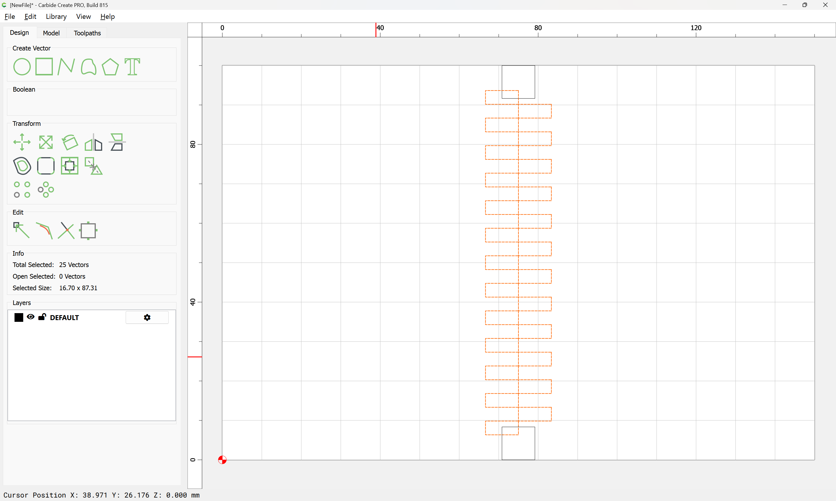
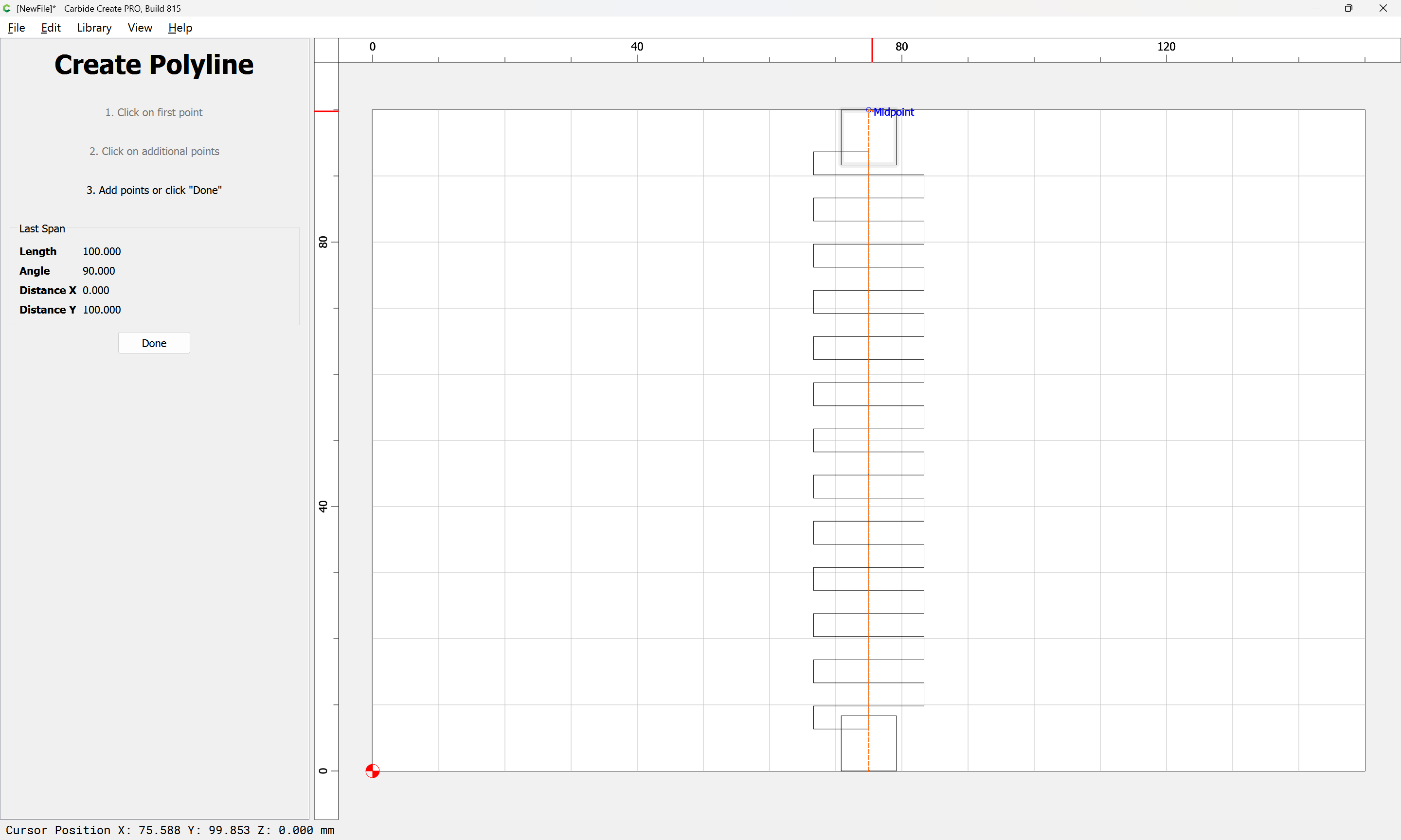
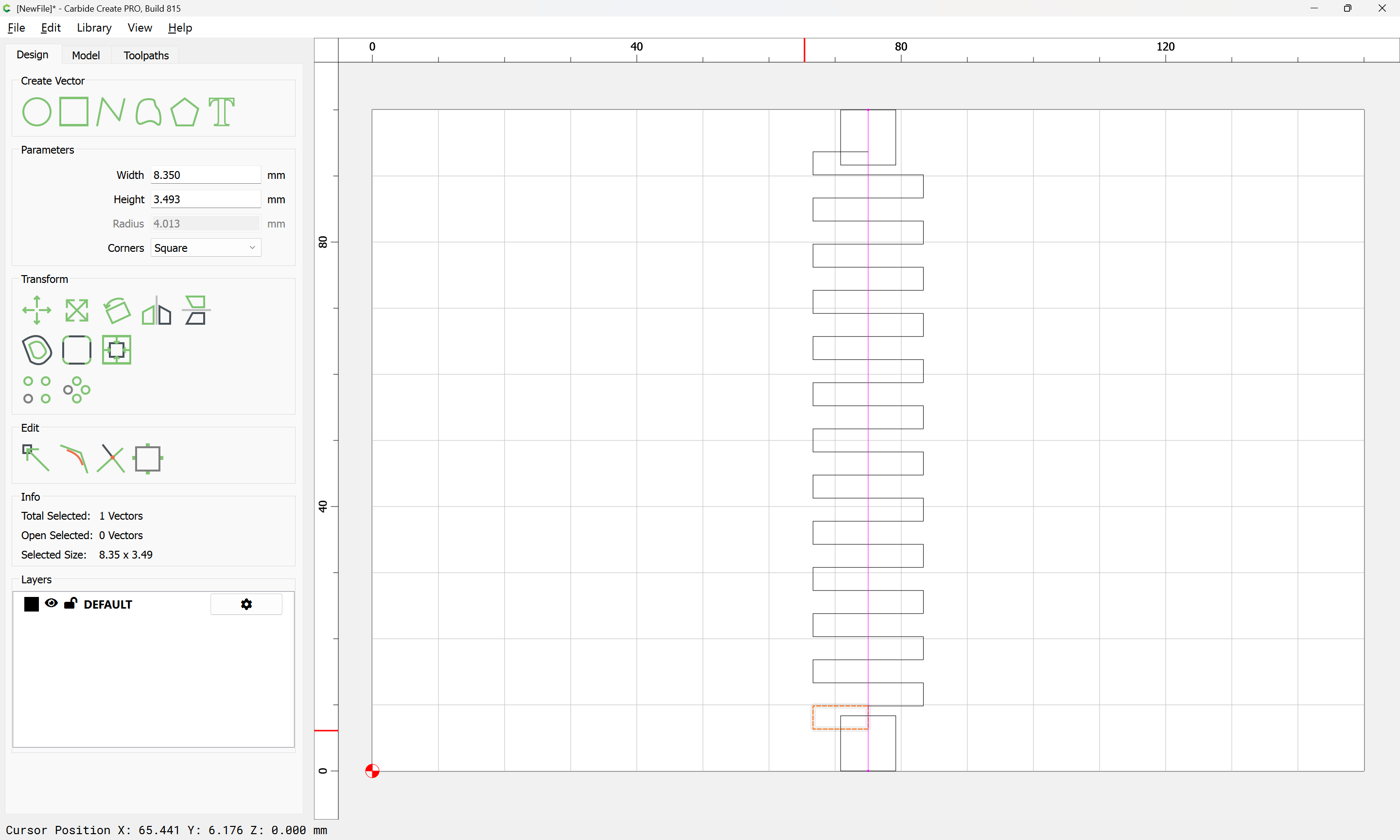
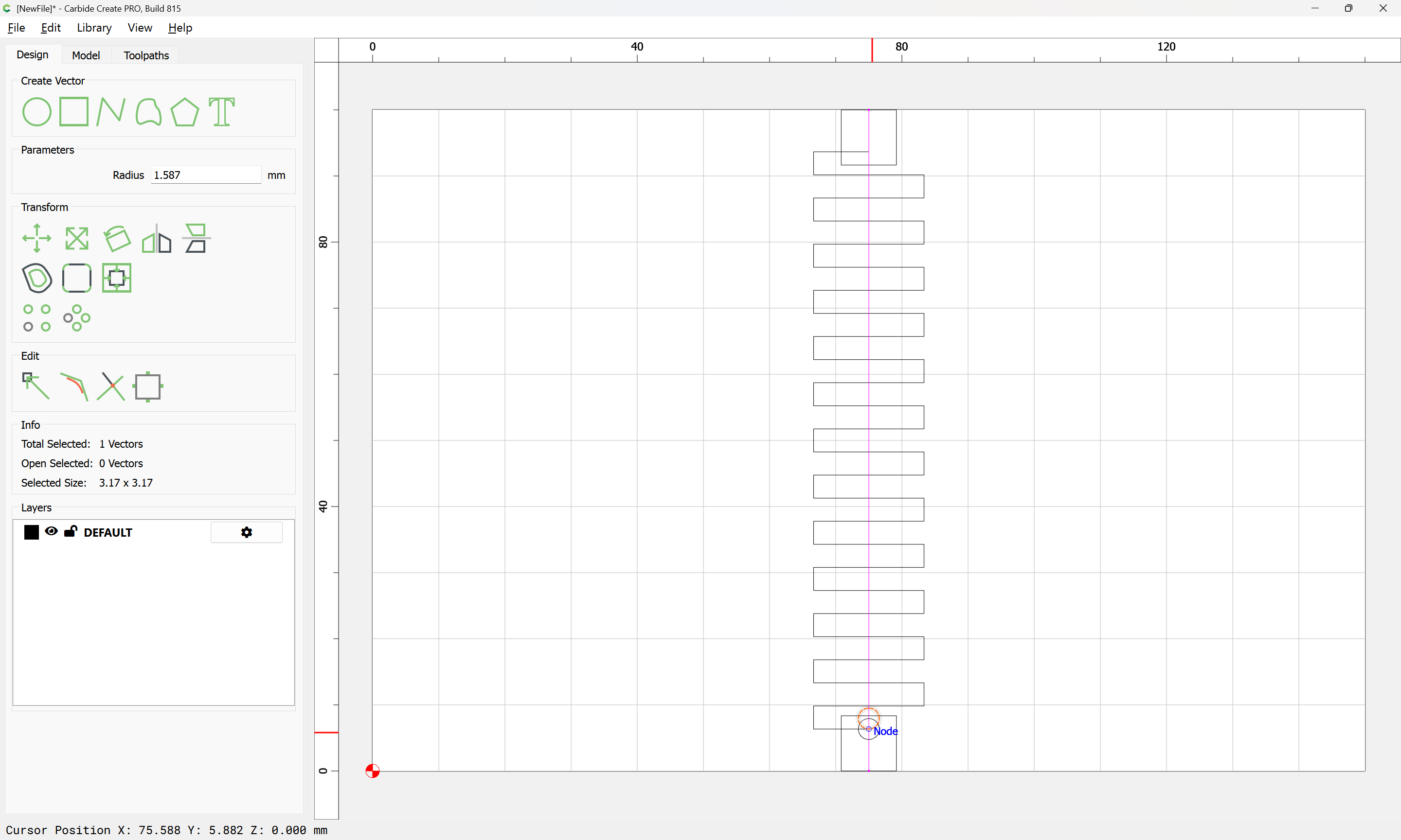
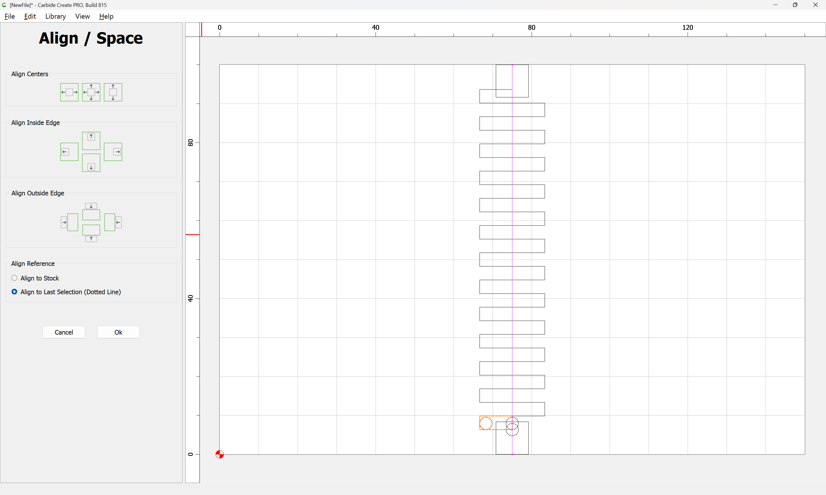
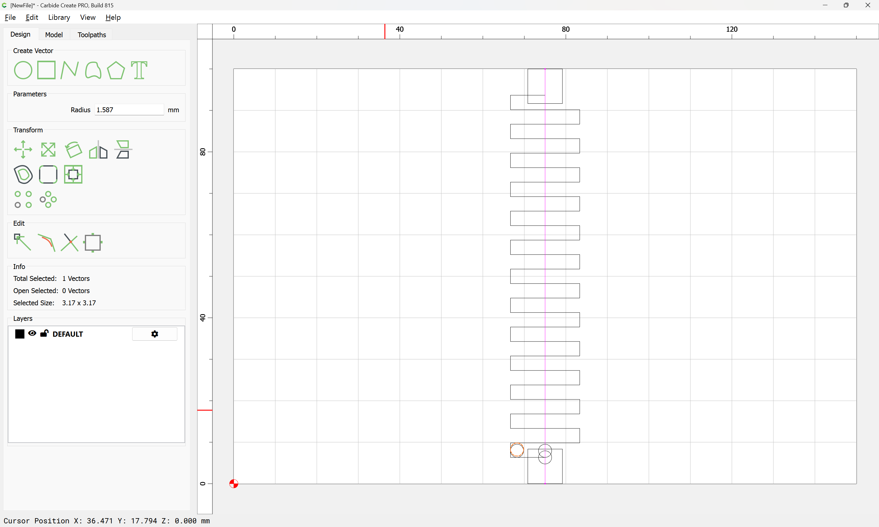
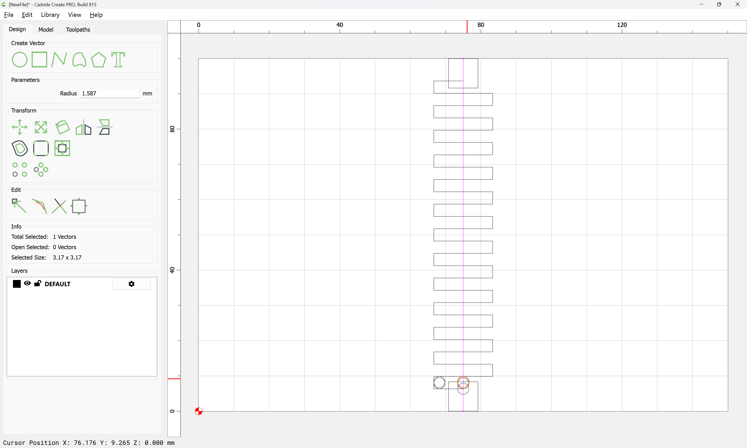
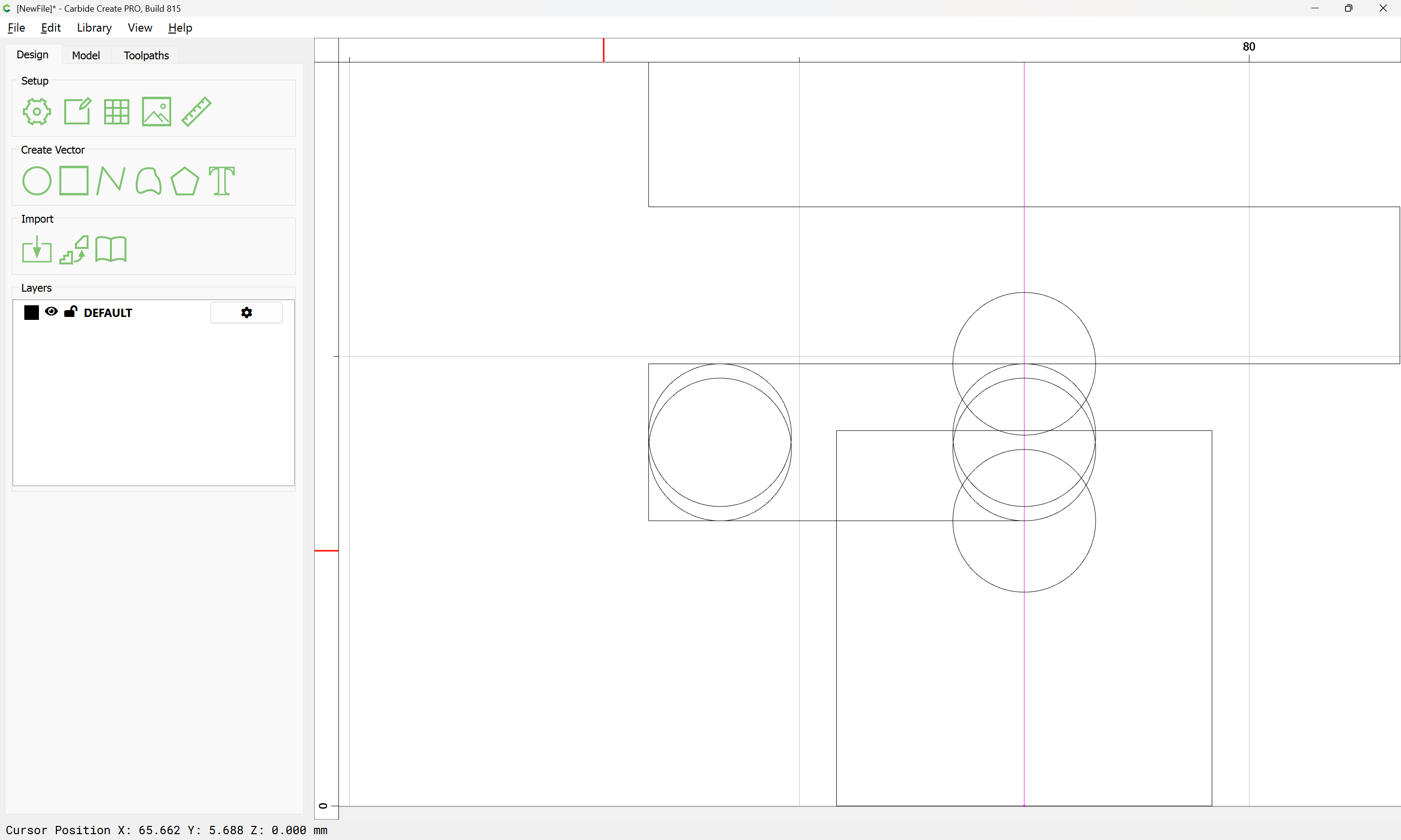
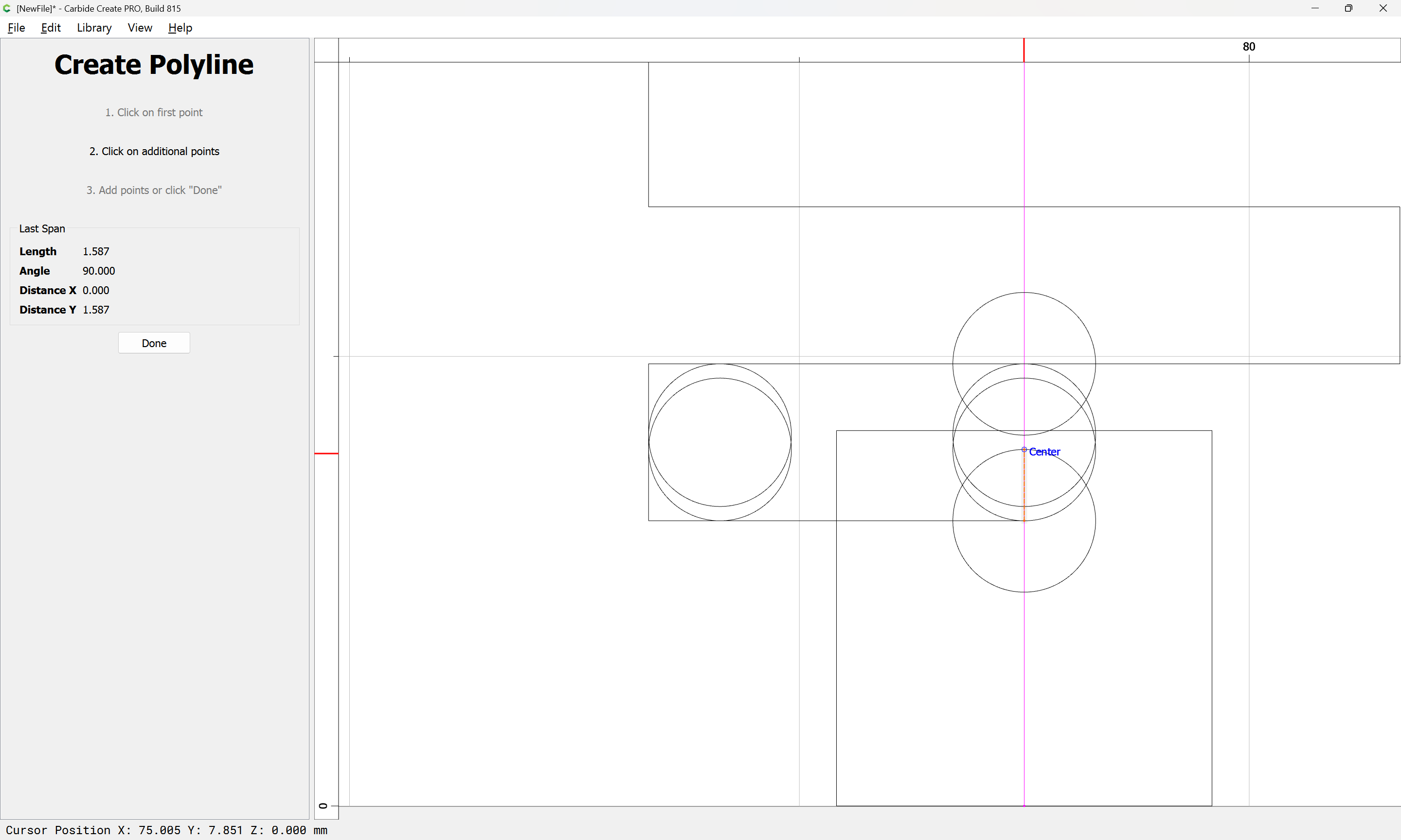
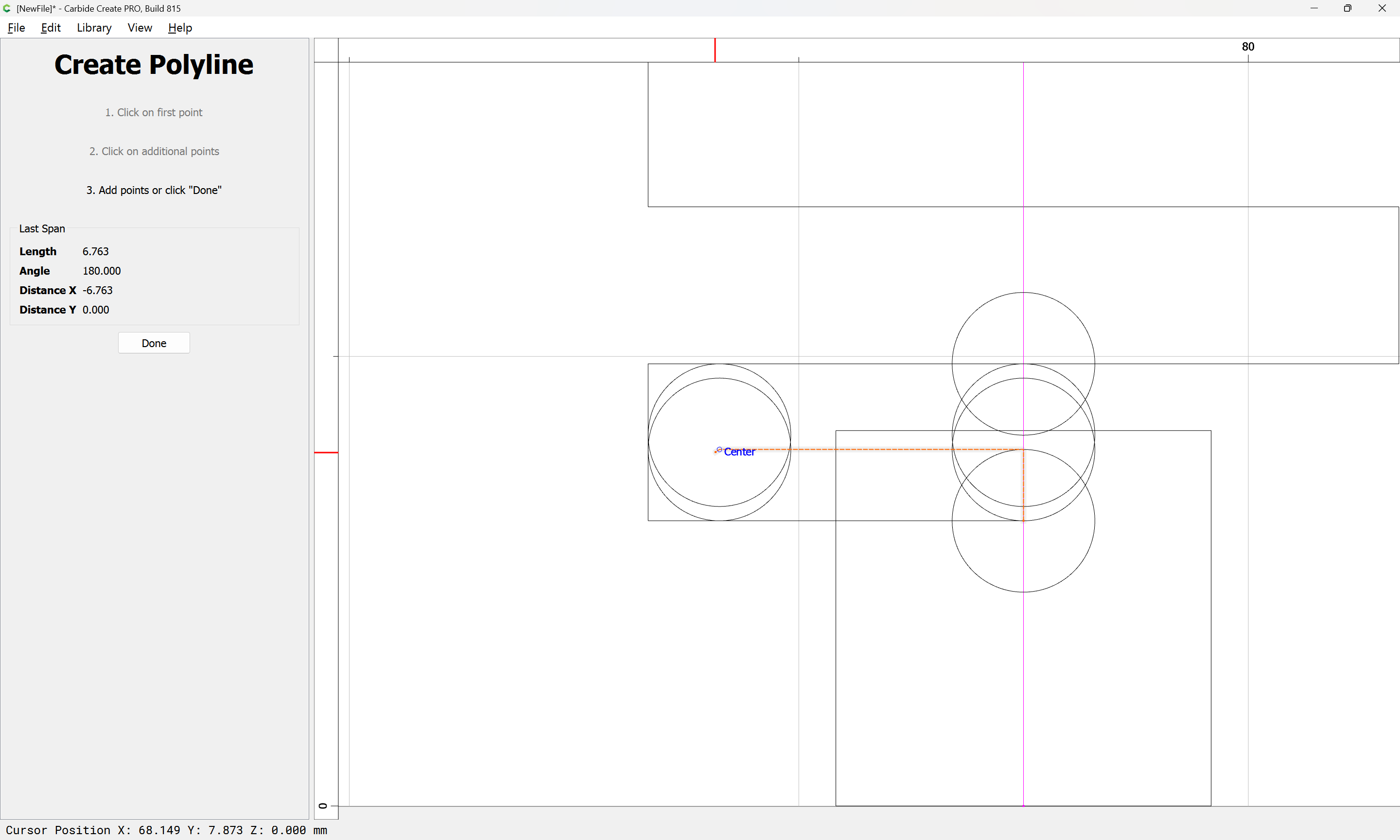
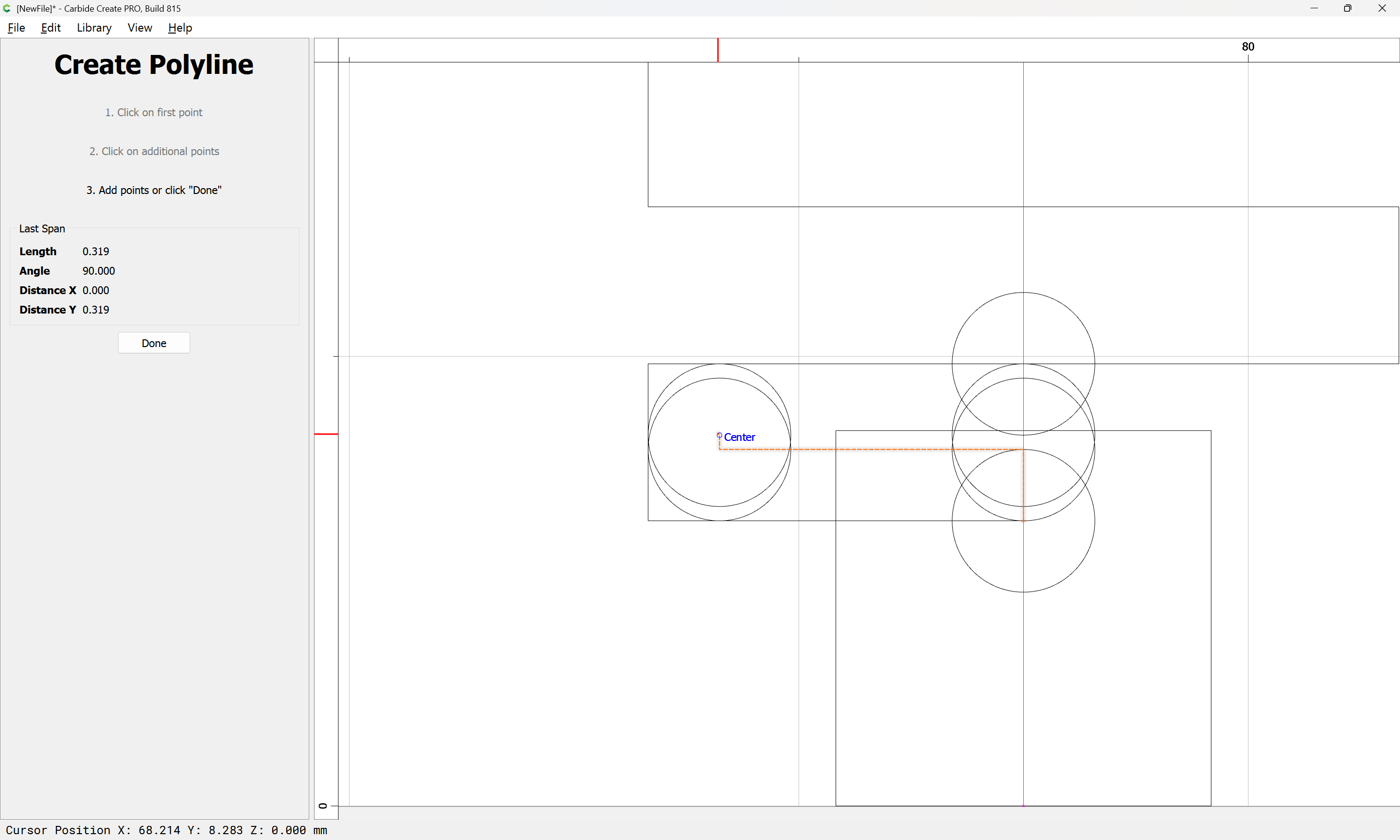
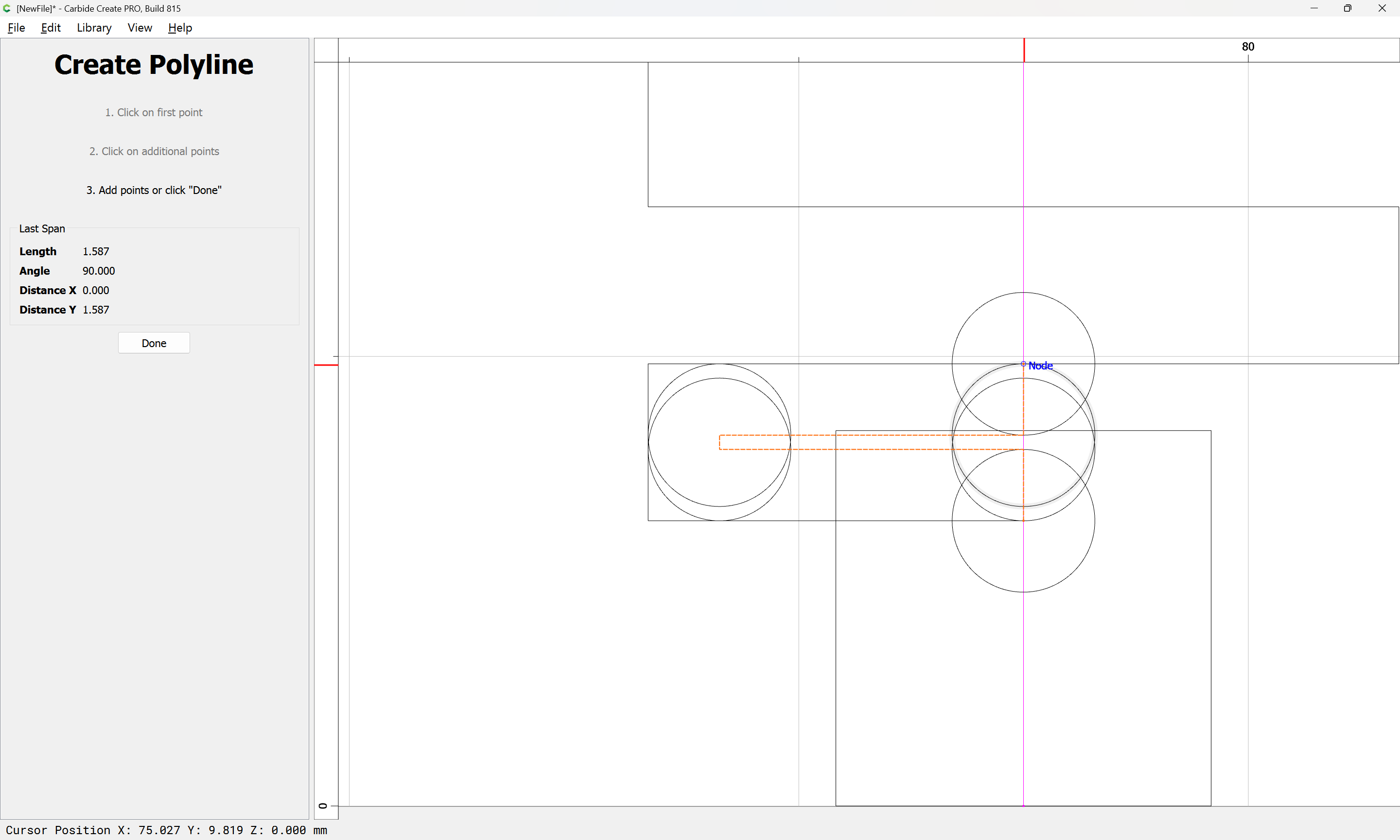
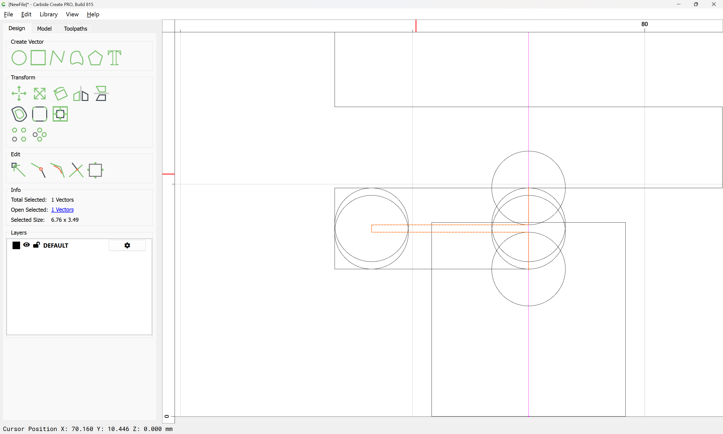
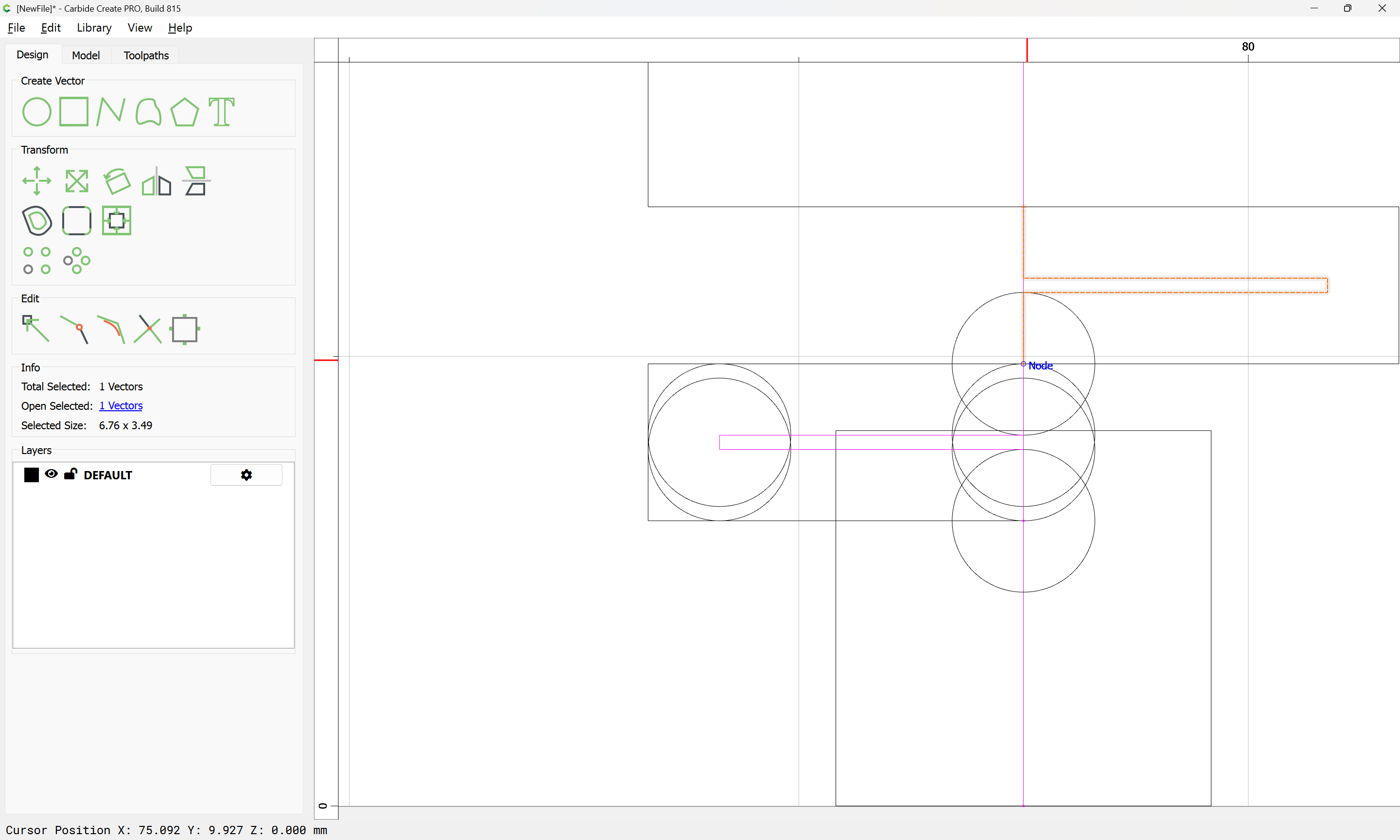
In setting up the initial values, the first question which arises is the number of pins — rather than doing the math, it is simple to just draw things up in Carbide Create:
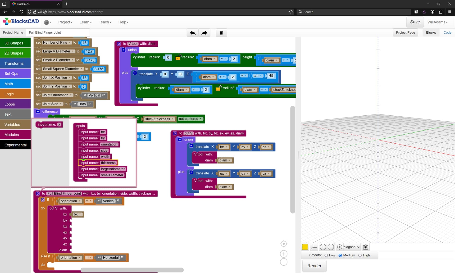
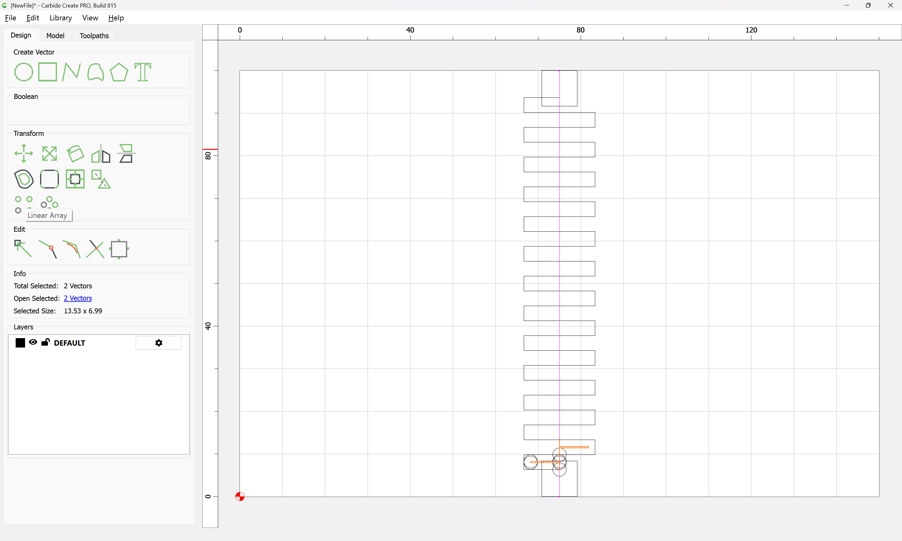
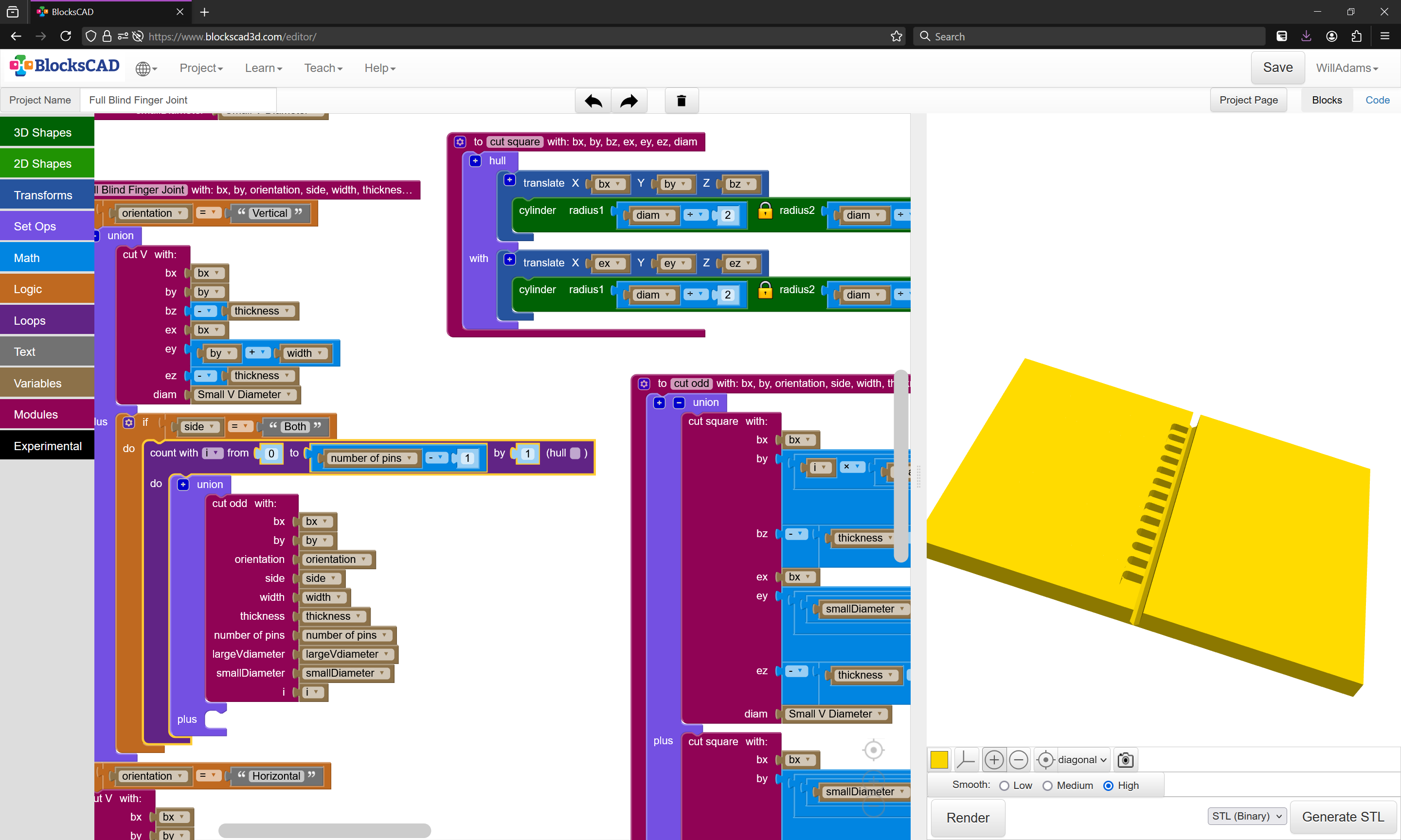
as discussed above, the cutting depth of the Large V diameter tool is a limiting factor, so it will be necessary to add additional cuts offset by some proportion of the Stock Thickness — which should be included at the appropriate if statements.
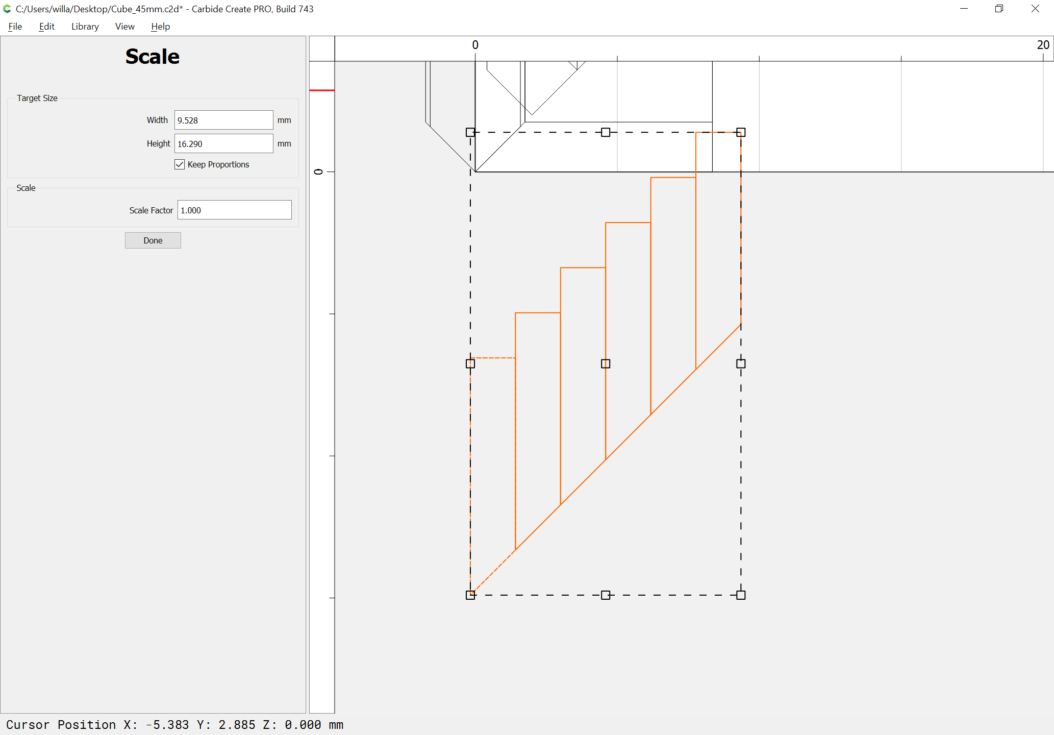
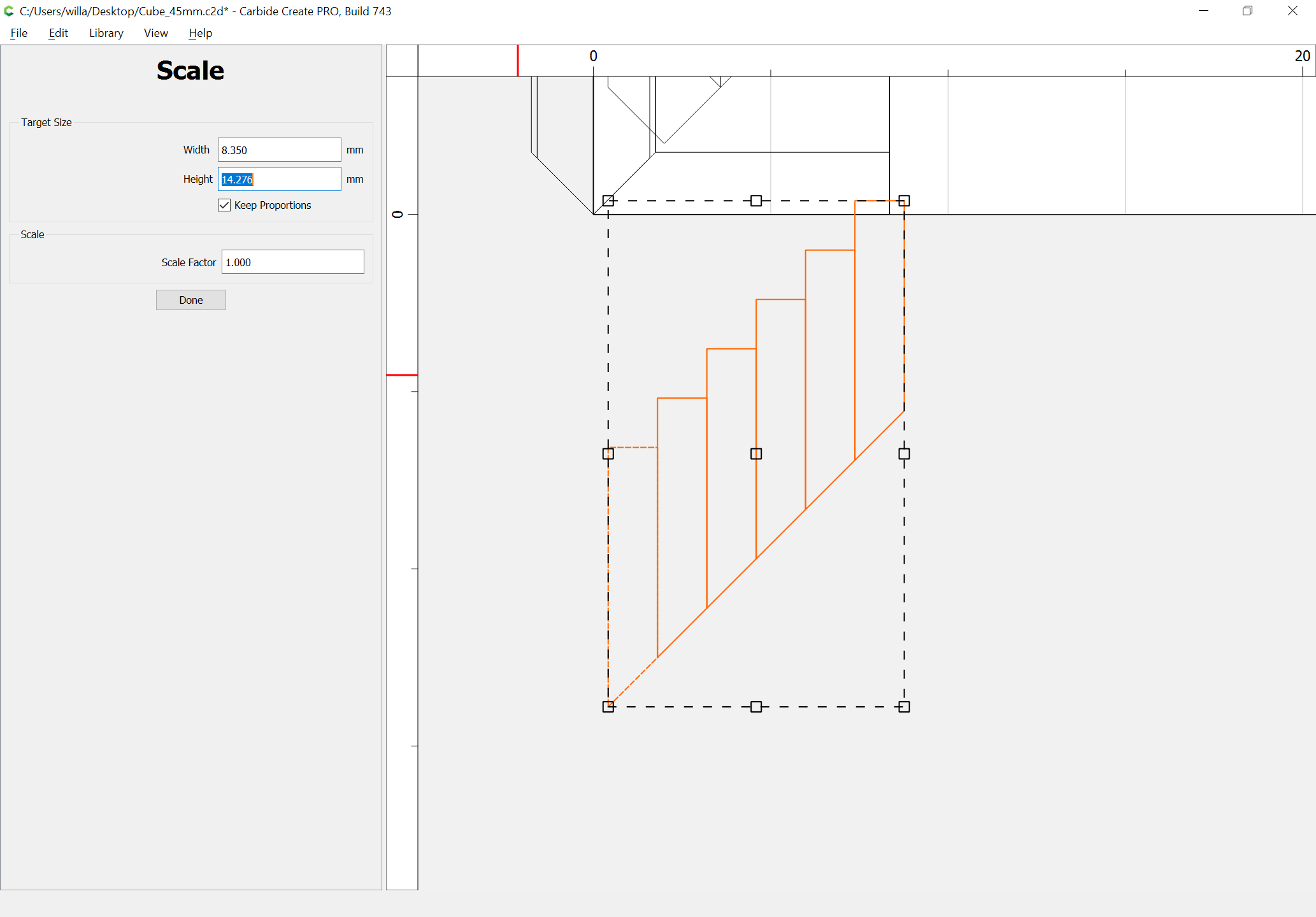
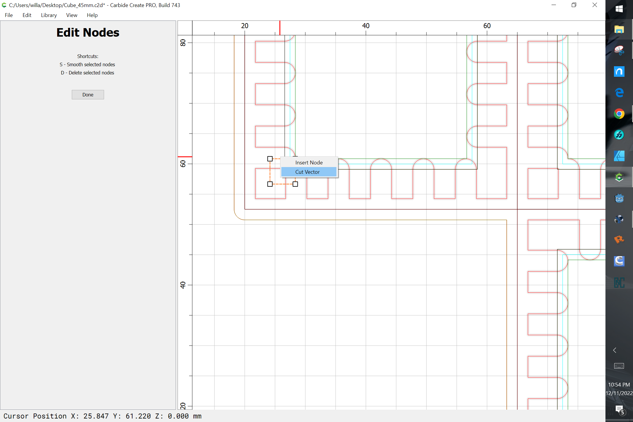
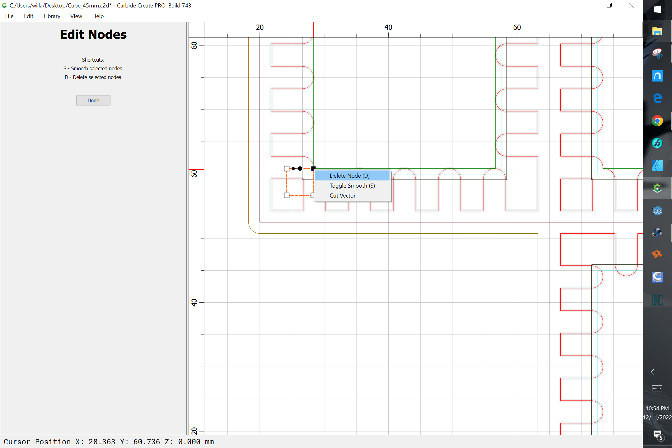
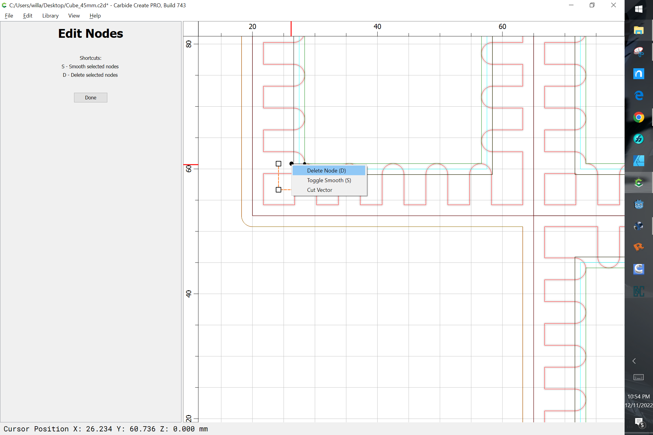
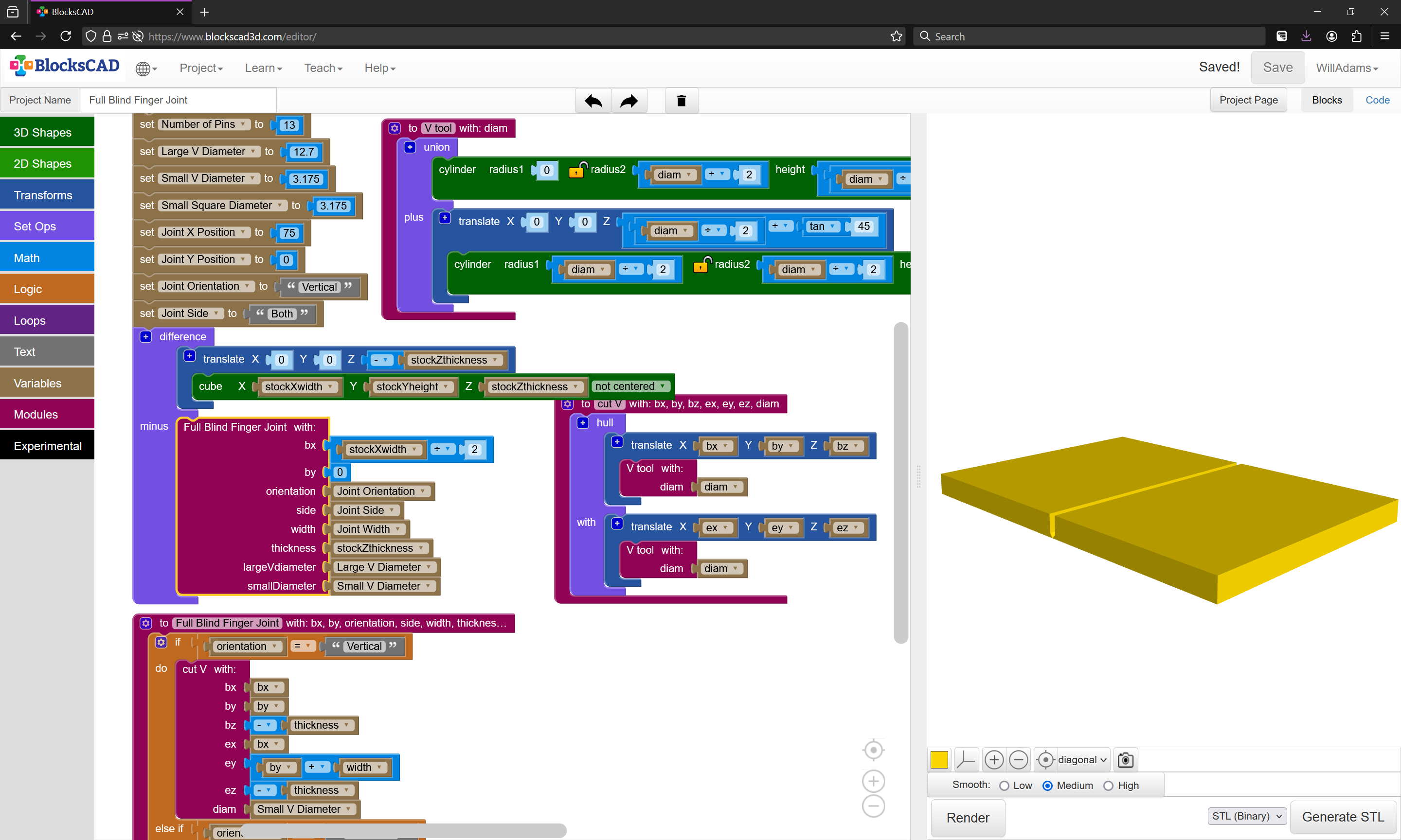
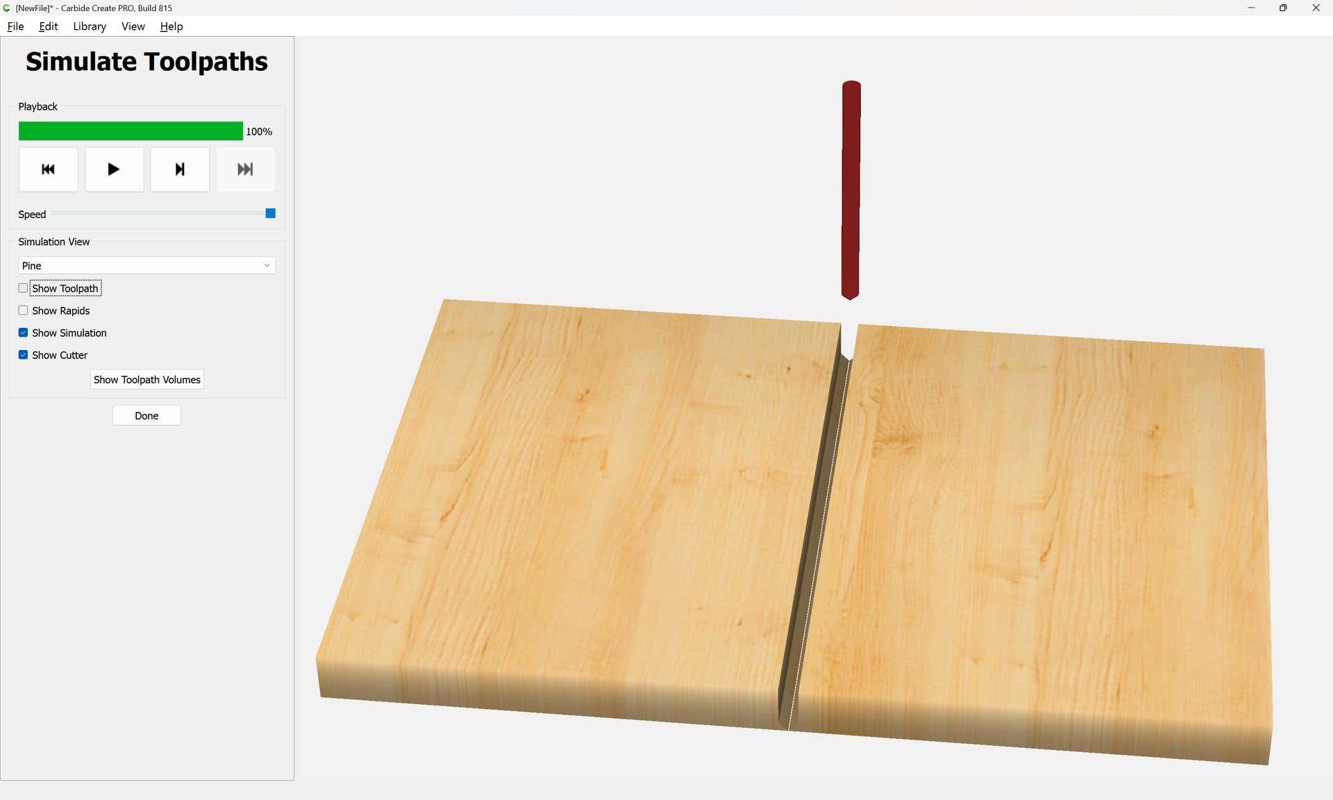
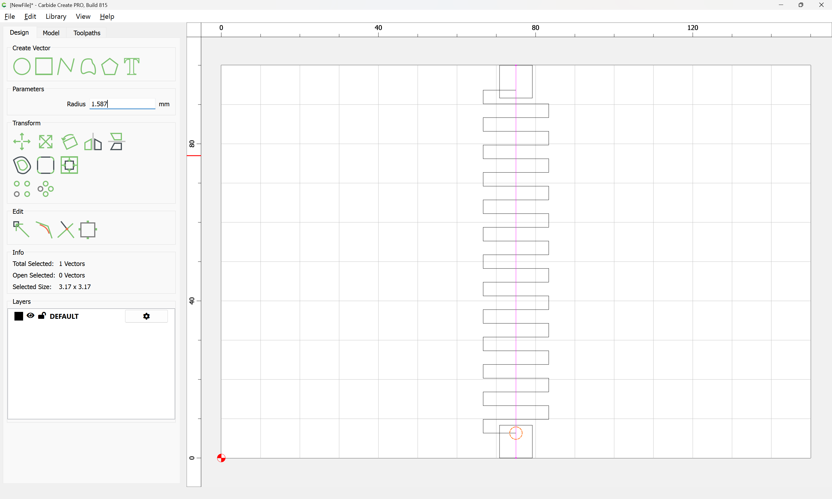
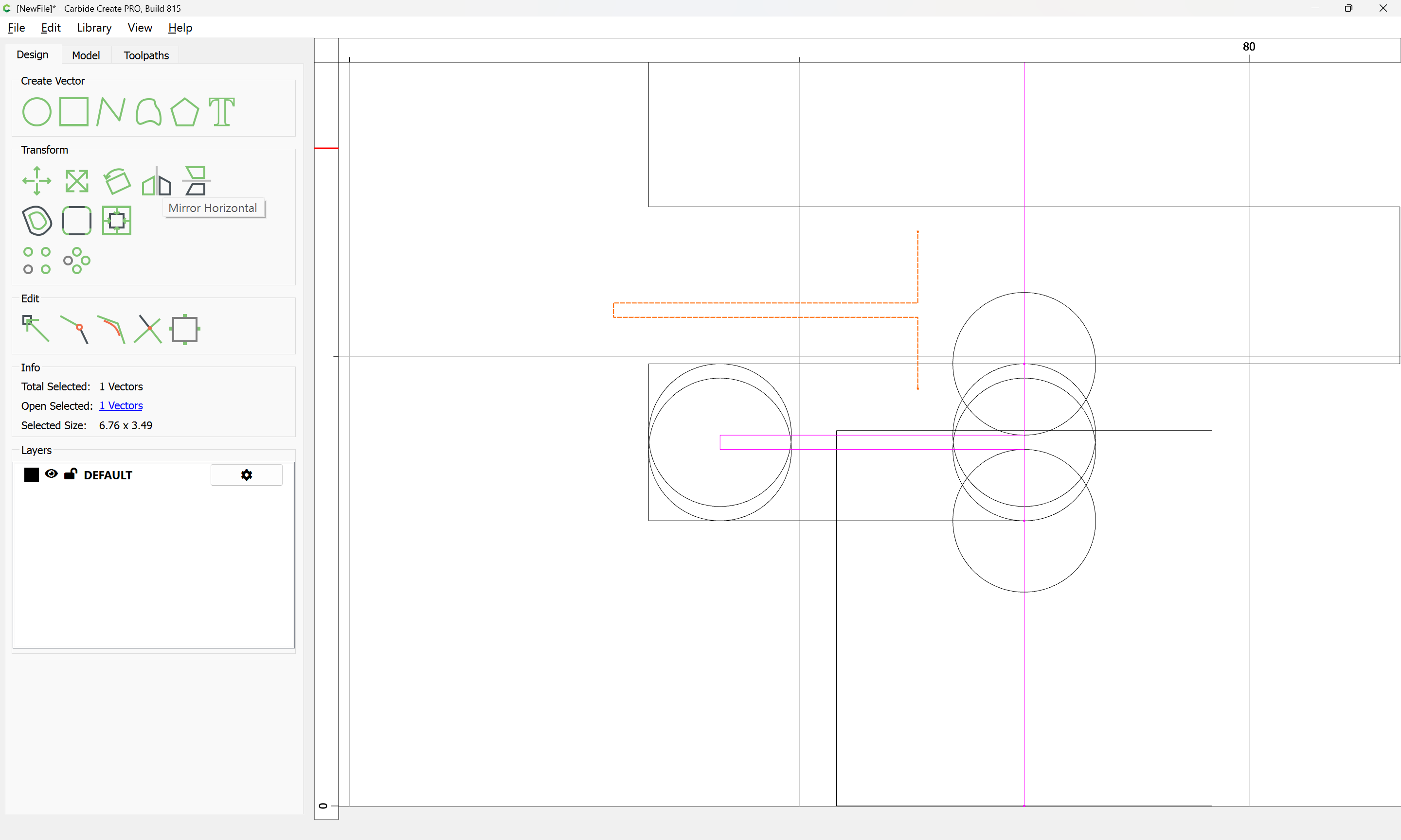
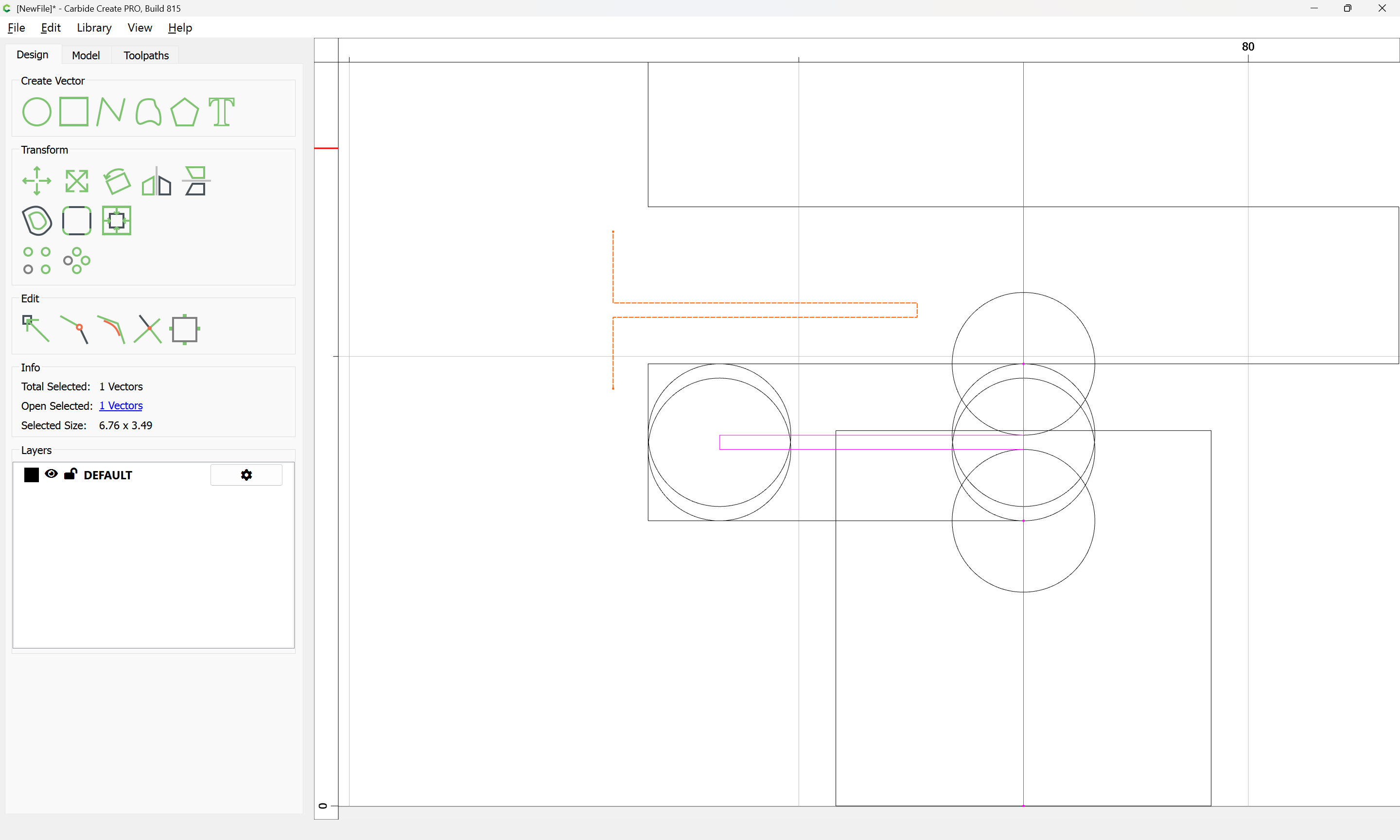
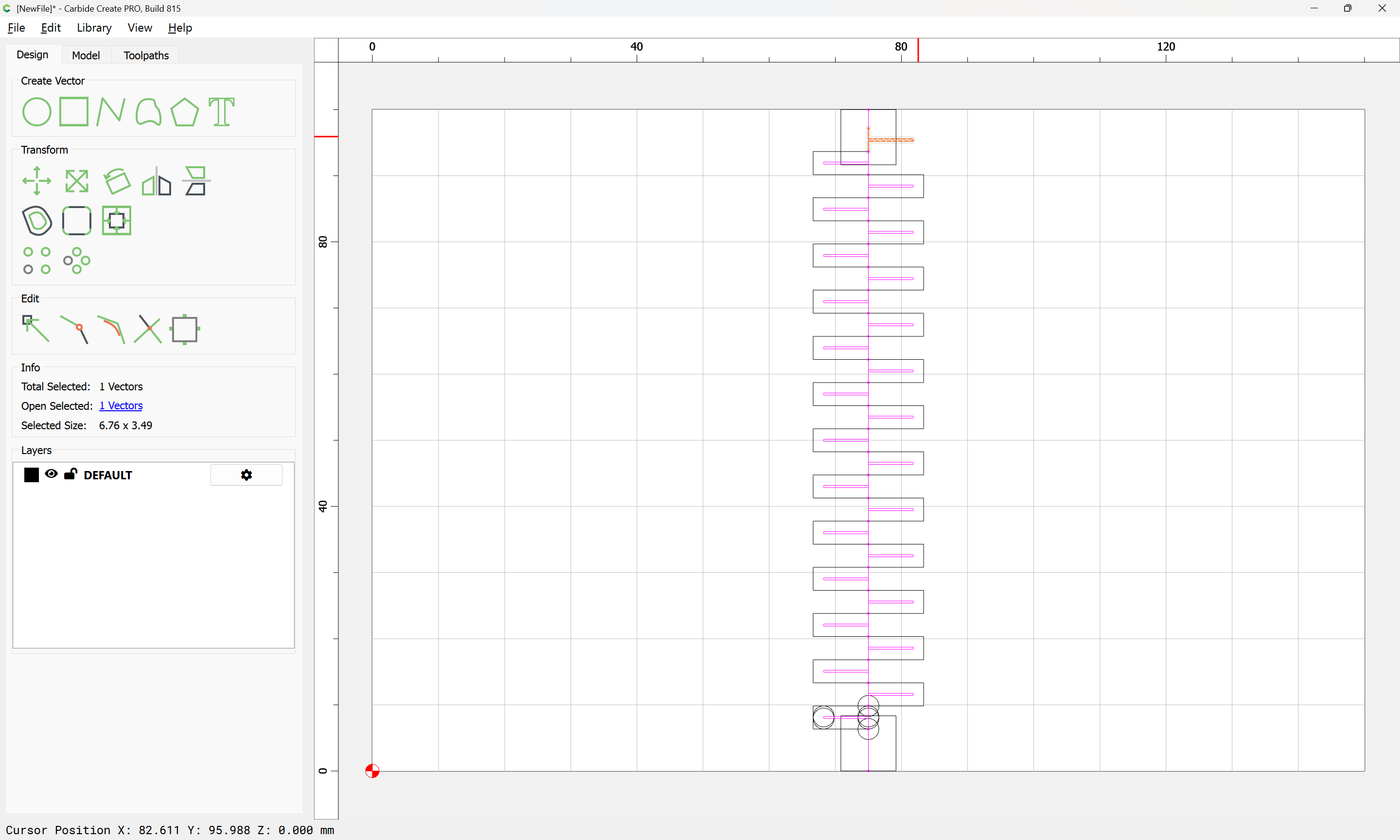
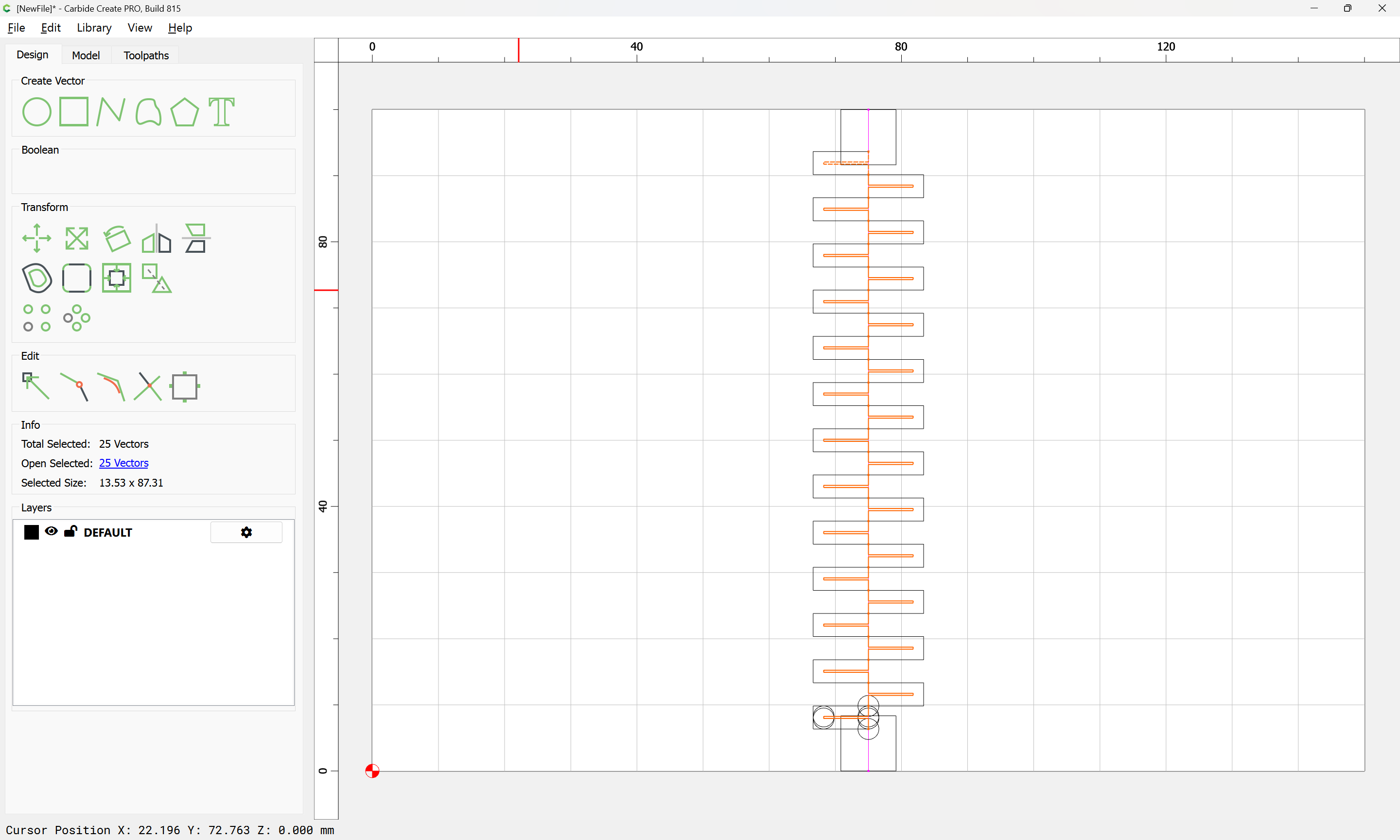
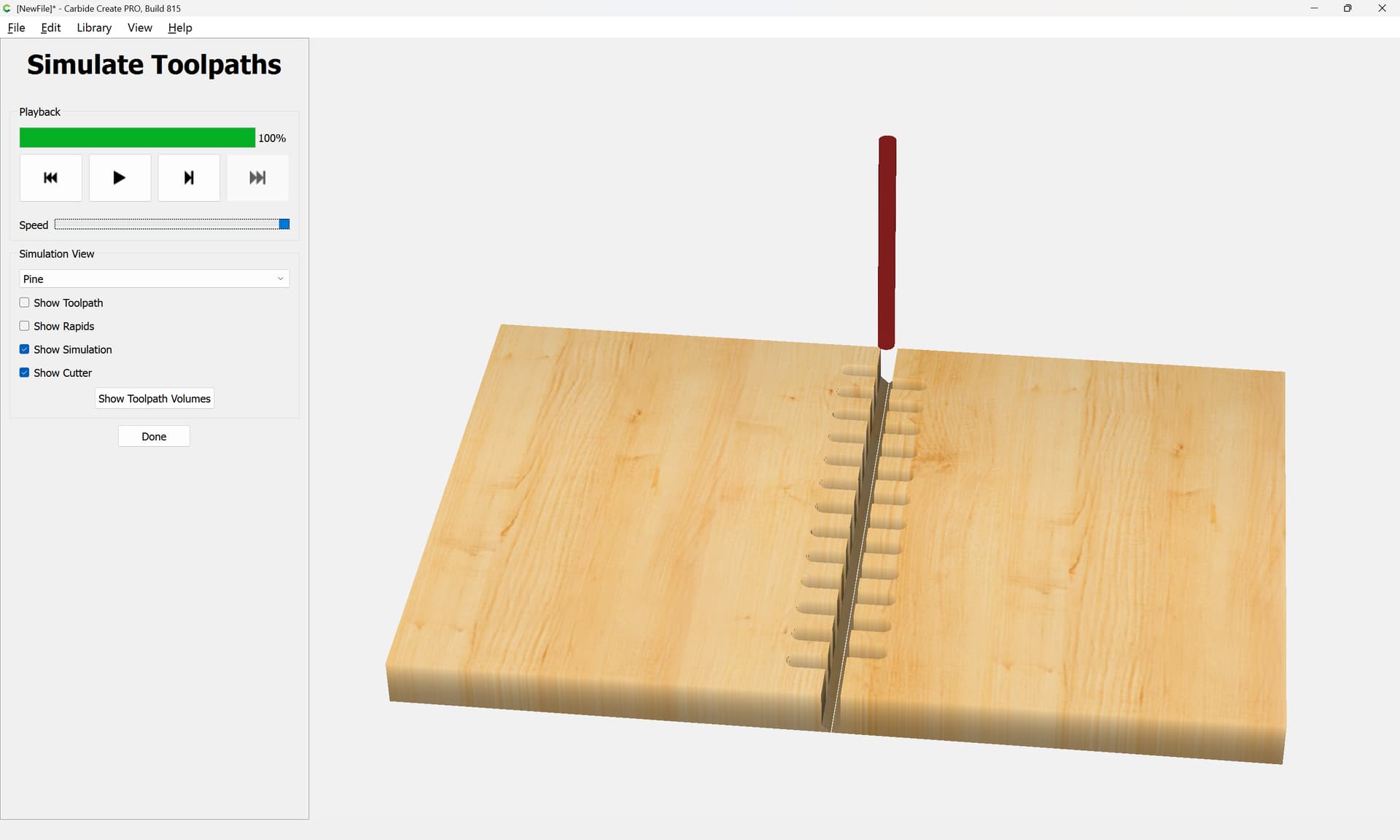
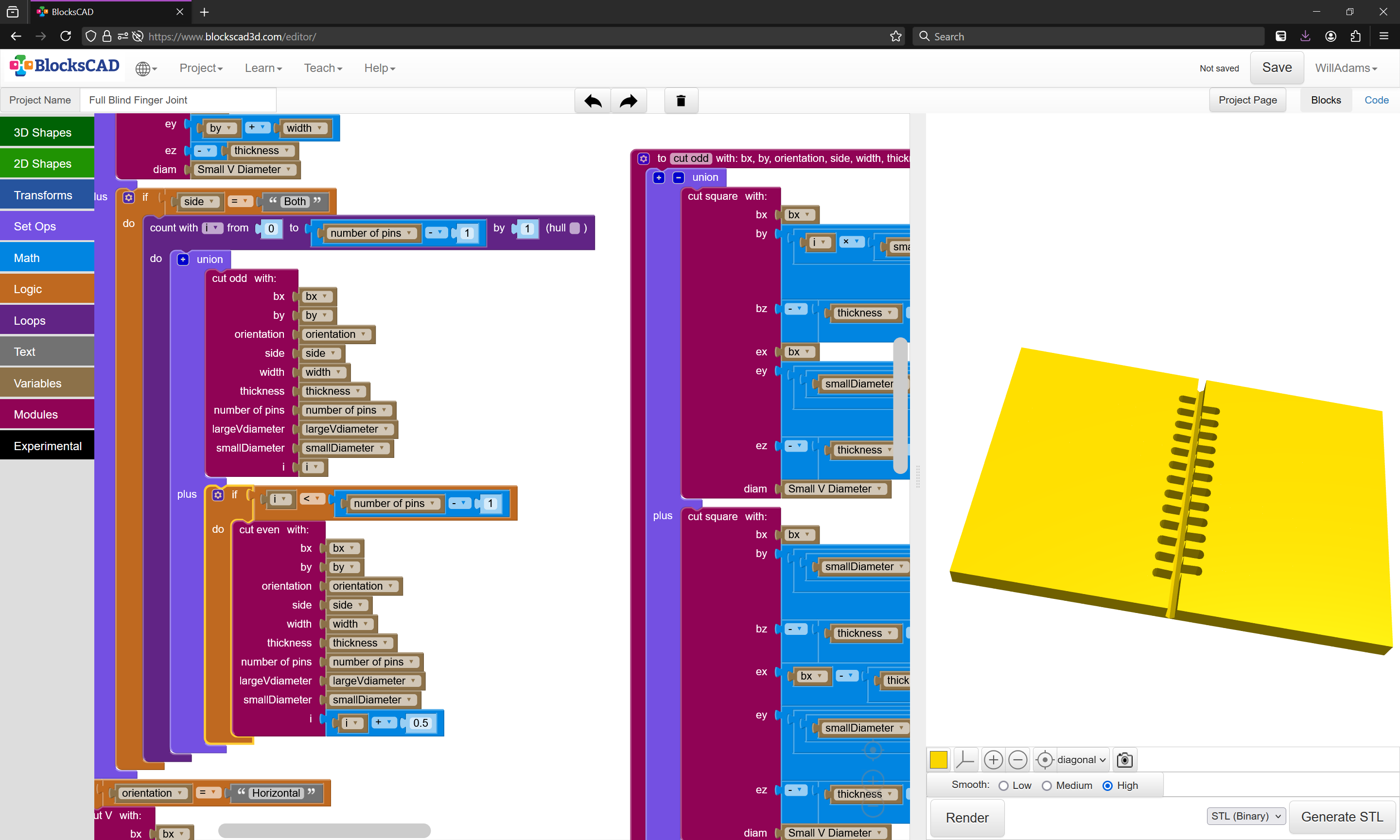
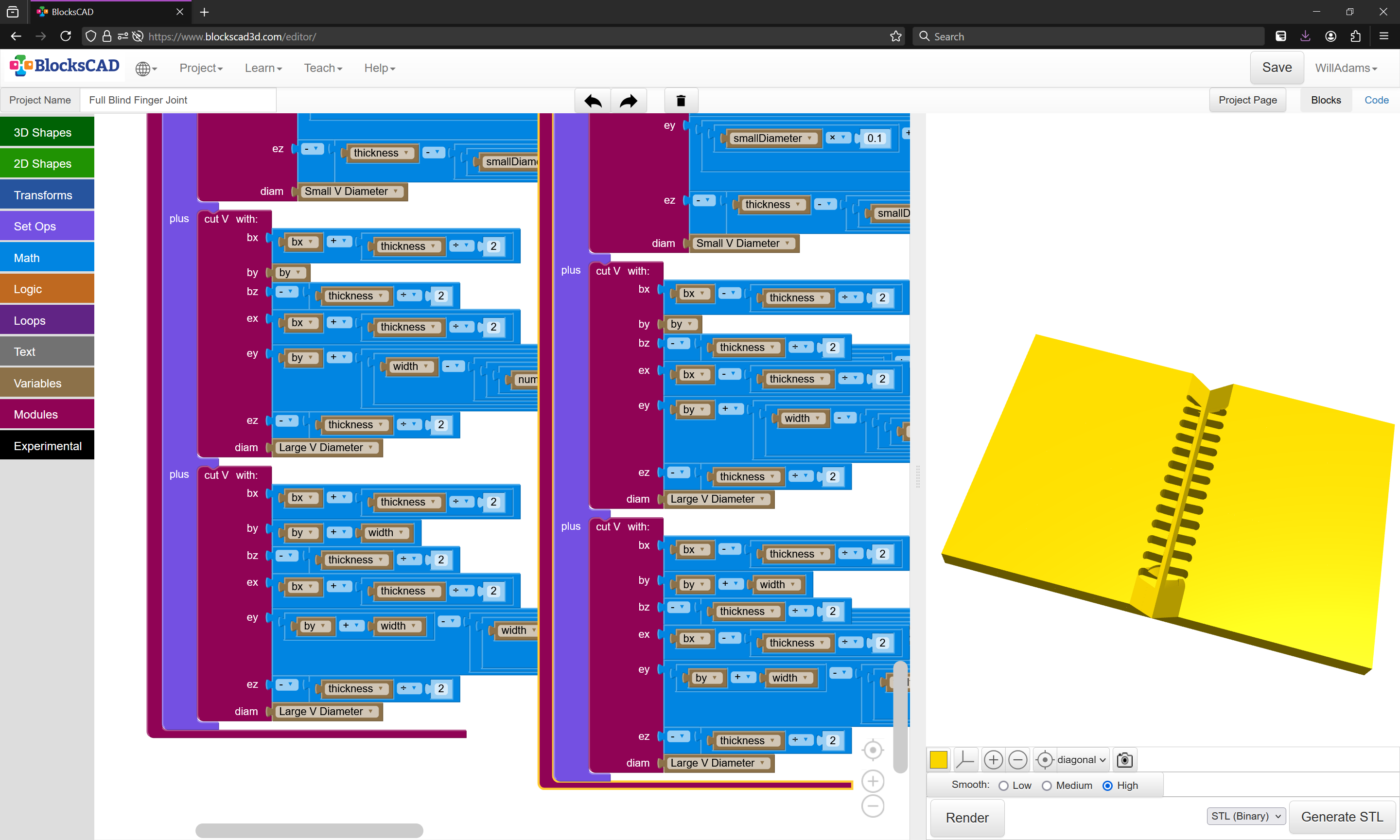
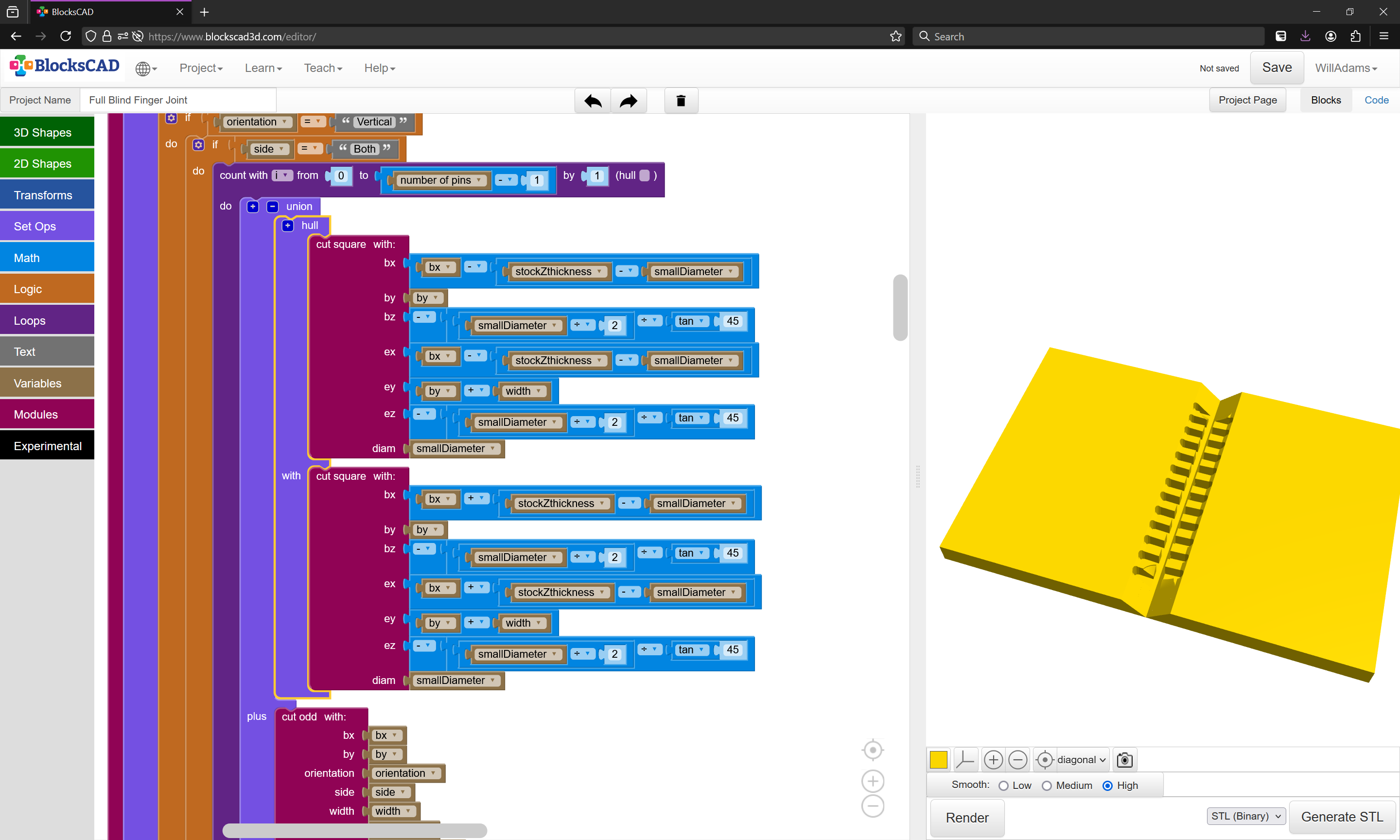
which just leaves the matter of working out how to get the pins to fit into the cut recesses which are necessarily rounded — one option would be to use a roundover tool working up the geometry of rounding each pin, but it is more expedient to make a V cut to the depth of the small tool and cut with a square tool in-between:
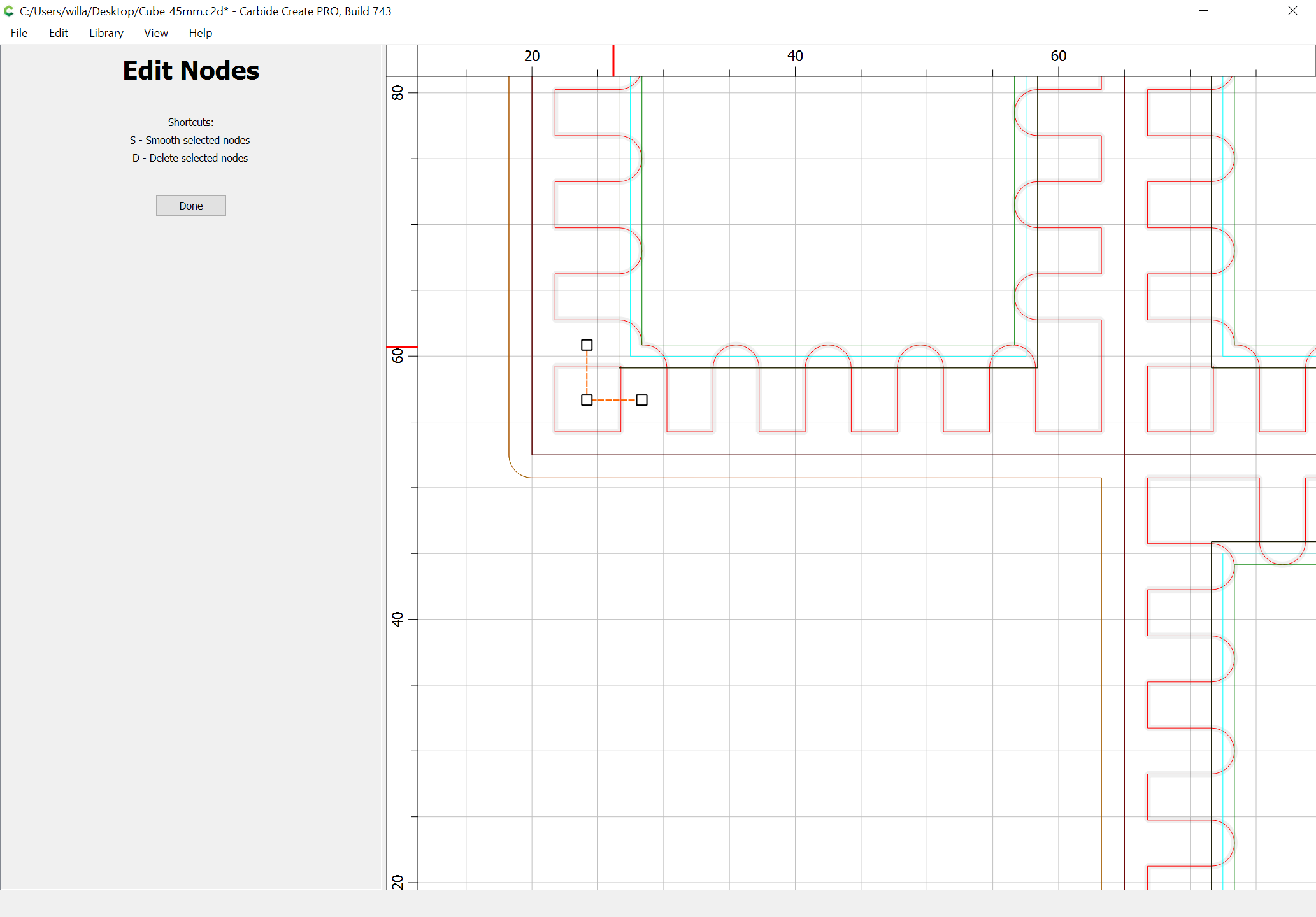
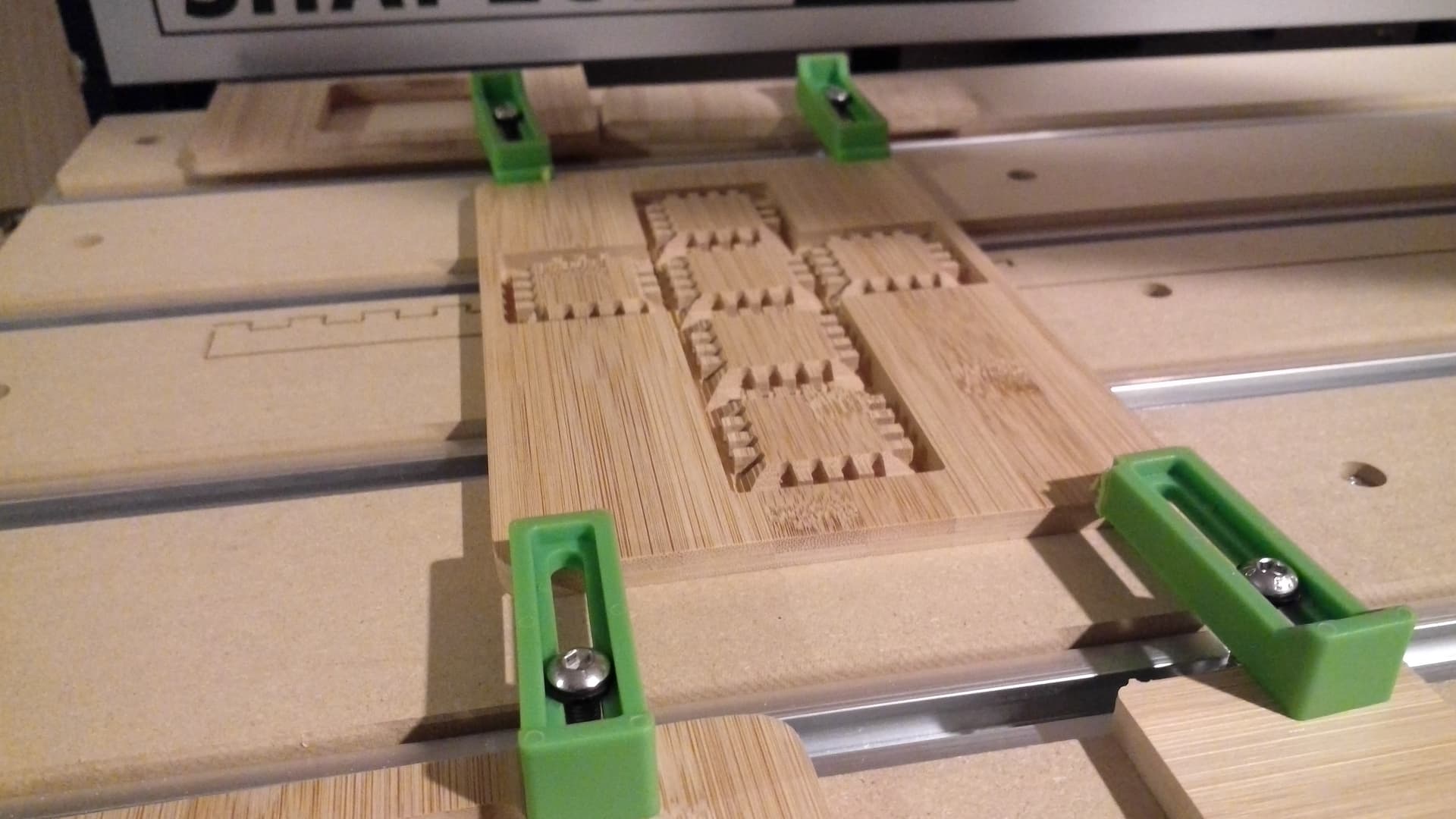
Using this technique, the cutouts are not square at the ends.
After assembly, will the half-circles at the end be visible on the inside of the corner?
Great article!
It’s a bit of a balancing act — usually the rounding won’t show — probably it would be best to pull them back and allow a bit more mechanical engagement with ends of the pins