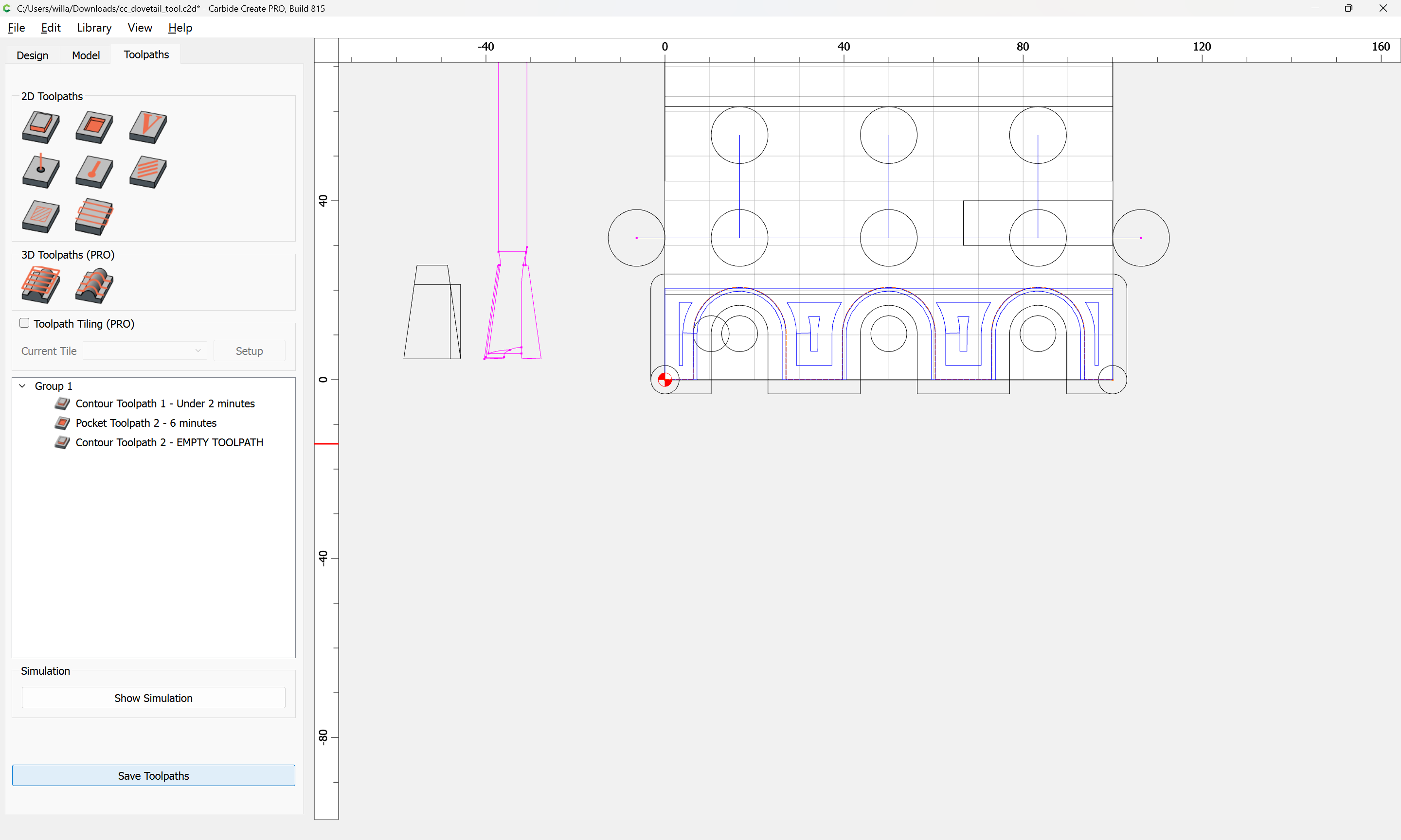
I tried this with first with a pocket cut using 1/4 end mill leaving a 1/2 inch wide pocket,. Then with the dovetail bit mounted set to finished depth tried to route a pocket set 1/4 wider, but at the same depth EMPTY TOOL PATH was the result. The dovetail bit is 14 degree x approximately 7/8 wide . There aren’t any in the tool list so I thought that I could tell the machine that I was using an 1/4 in. Endmill bit
Dovetail tools are not supported by Carbide Create.
Rather than using a Pocket Toolpath you will need to manually draw up the path you wish for the tool to follow and set up a cut which matches how you wish to make the cut, see:
That said, why do a dovetail on a machine? They’re easily cut by hand, or, if you wish to do joinery on the machine, there are options which don’t require 3 setups (minimum) such as:
I’m sorry, but what do you mean manually draw a tool path? I thought I was doing that using a pocket tool path.
Did you draw this with poly line, I don’t understand
Yes, you have to draw the desired toolpath with the Polyline (or Curve) tool, then assign a No Offset Contour toolpath.
If you’ll note the specifics of the dovetail which you wish to cut, and the tool which you plan to use (provide a purchase link with full specifications) we can walk through this with you.
Have you worked out how you will handle workholding?
Why not use a full blind box joint instead?
Amanda 45828 I understand that with a 1/4 “ shaft it have to be set to slowly make the cut, kind spiraling to full depth. Yes,I ‘ve worked out the work holding, but it can be vastly improved.
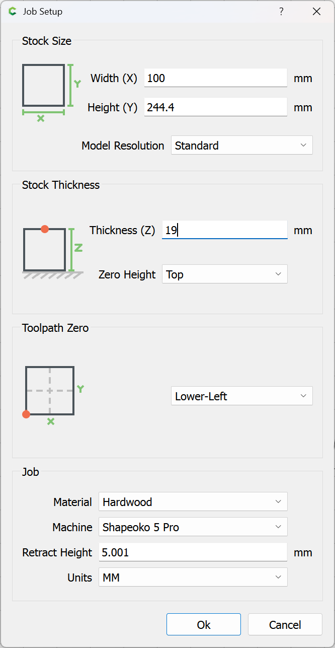
How thick is your stock?
How wide is the joint?
How many dovetails do you want?
With what spacing?
Described as:
45828 Carbide Tipped Dovetail 8 Deg x 1/2 Dia x .825 x 1/4 Inch Shank
There is a DXF profile of the tool available:

and the relevant geometry in terms of cutting is:
which we define as:
8 — dovetail
08 — angle in degrees
07 — indicates 1/2" cutting diameter
9 - calculate based on radius/angle
which in code will be called using a module which begins its definition as:
def dovetail(self, dt_bottomdiameter, dt_topdiameter, dt_height, dt_angle):
so:
dovetail(12.7, 6.816, 20.95, 8)
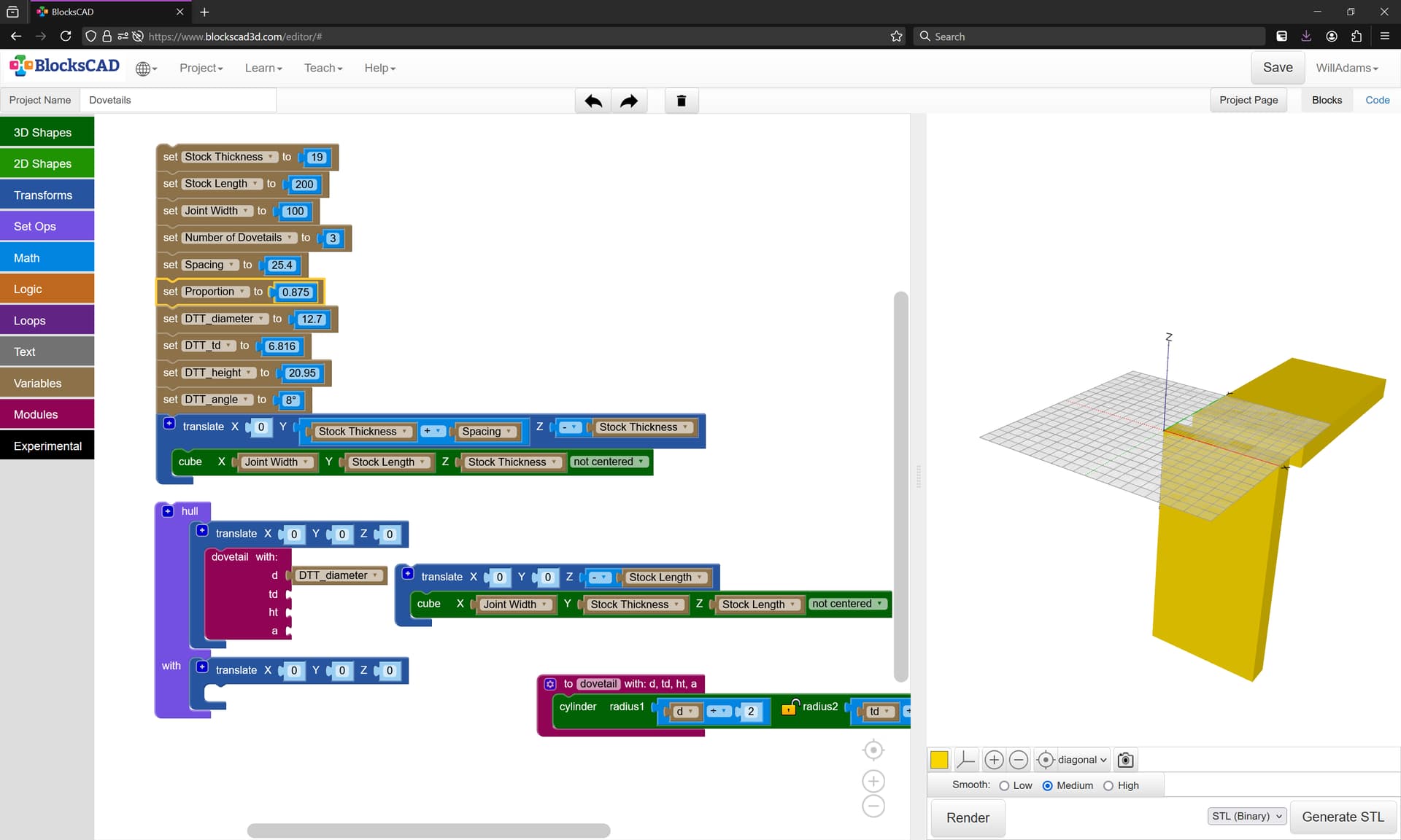
As per usual, we rough out a pair of files in BlockSCAD and Carbide Create. This is especially important for this project since we need to cut two different pieces of stock, int two different orientations, which Carbide Create doesn’t really facilitate.
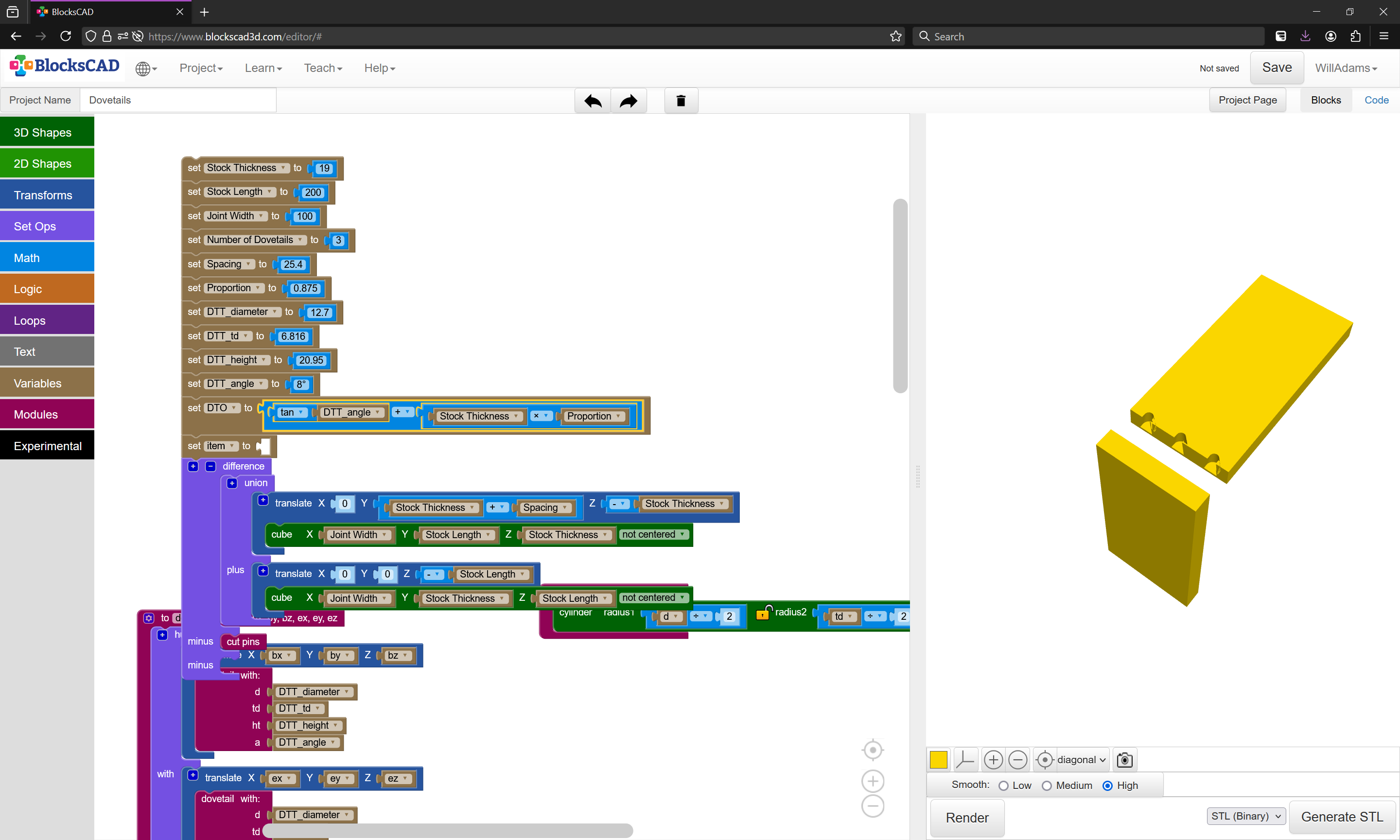
First, BlockSCAD:
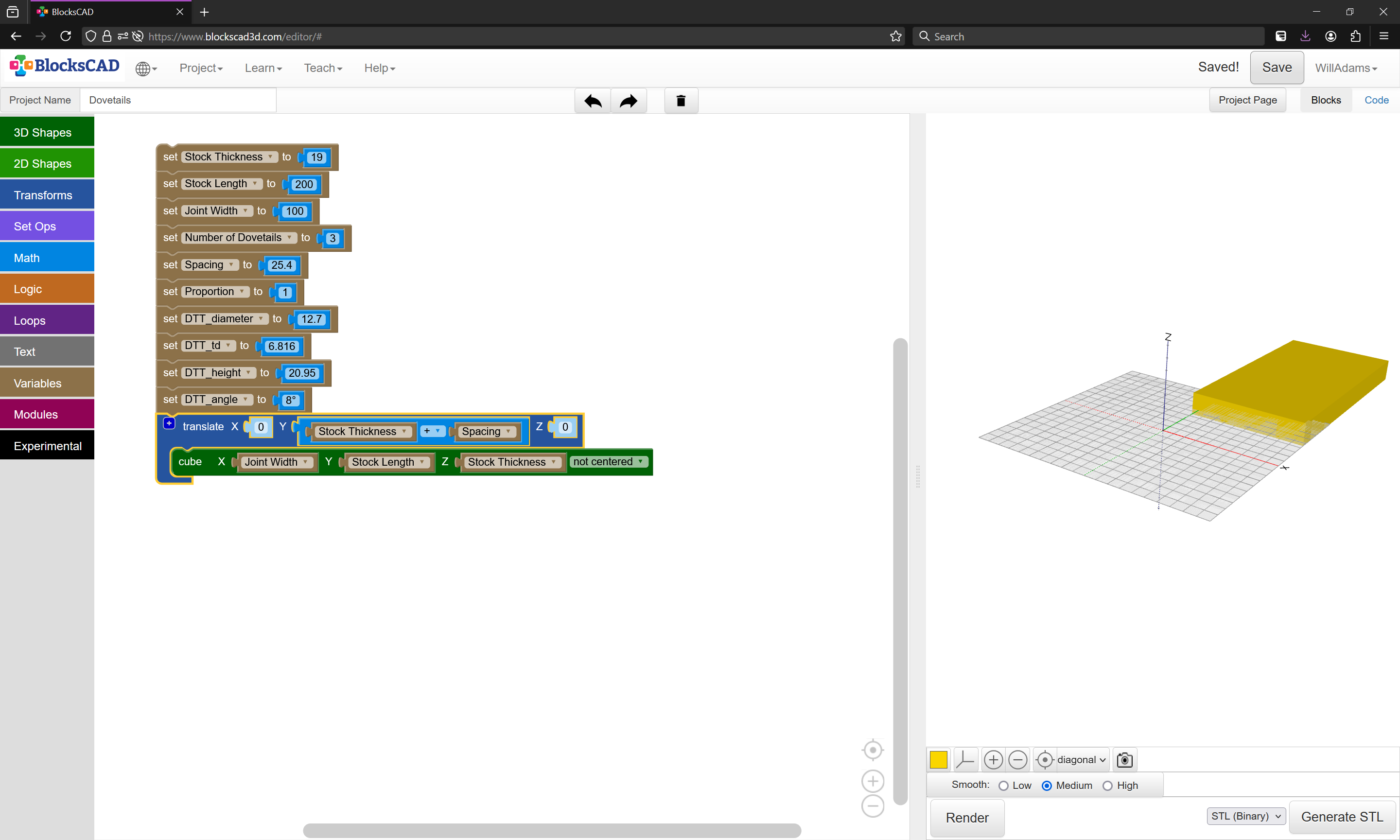
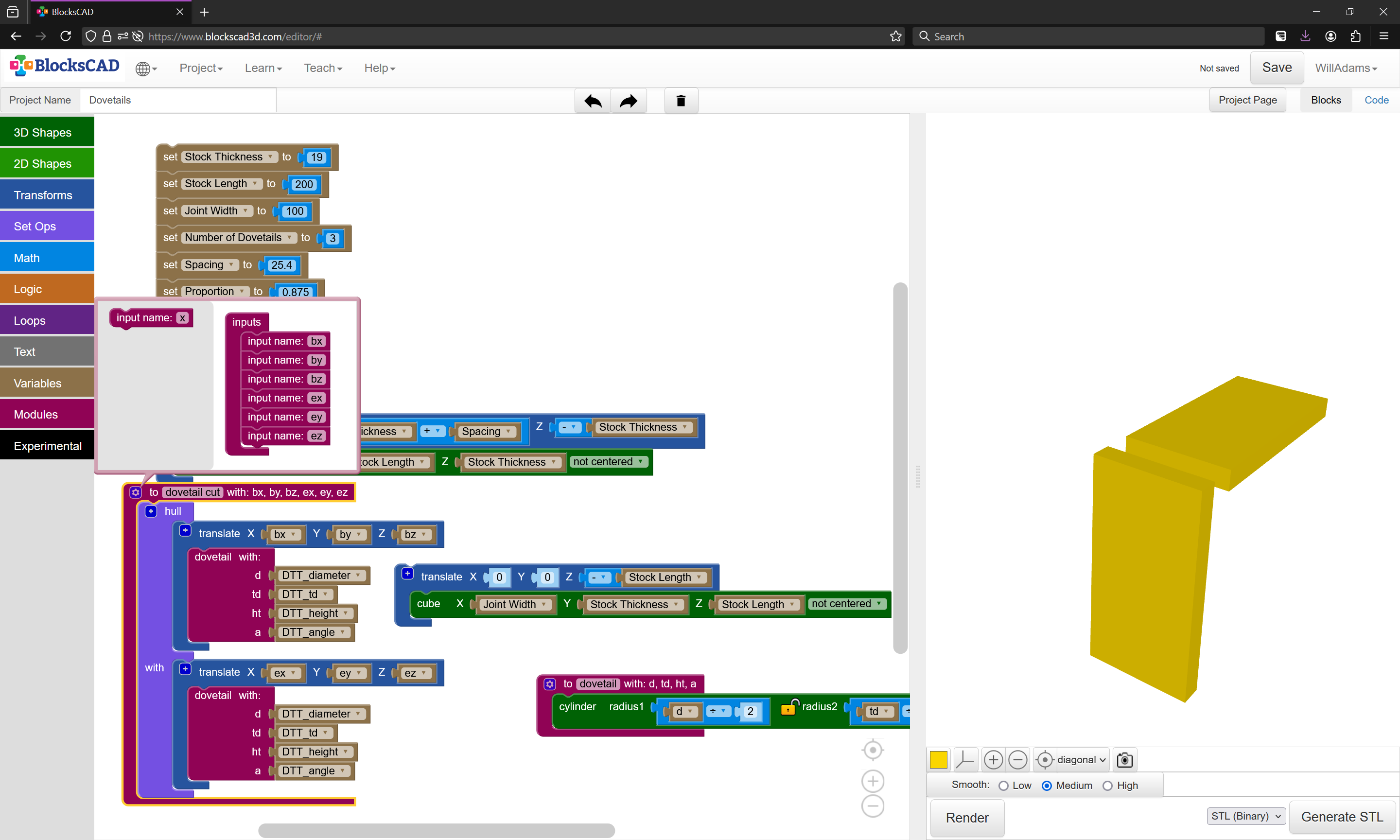
Placing the piece of stock for the horizontal cut is straight-forward — but it’s simpler to position it back by Stock Thickness and Spacing. The vertical piece of stock is placed similarly:

and then positioned so that the origin placed at the top-left corner:
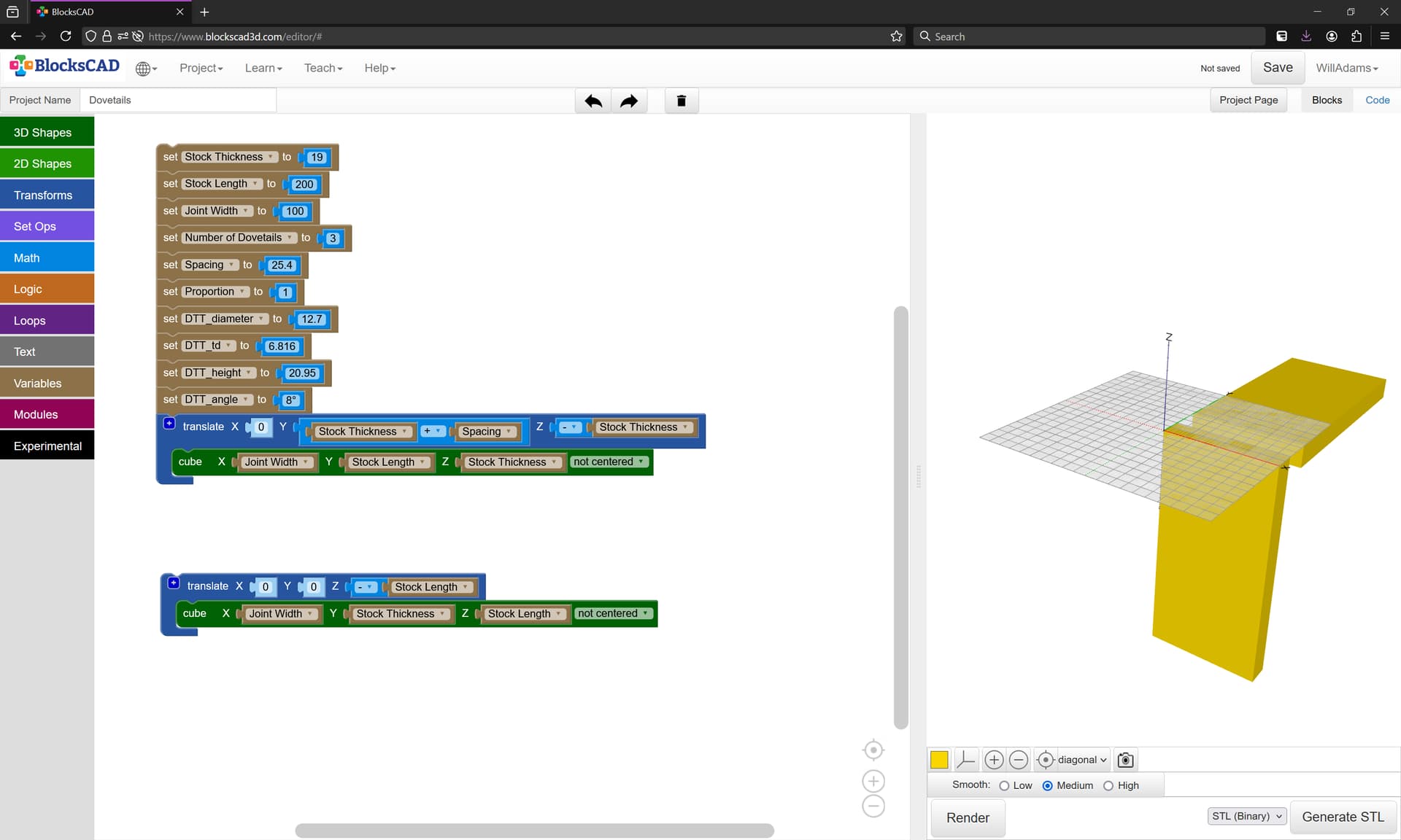
at which point the tool may be modeled, and the toolpath defined.
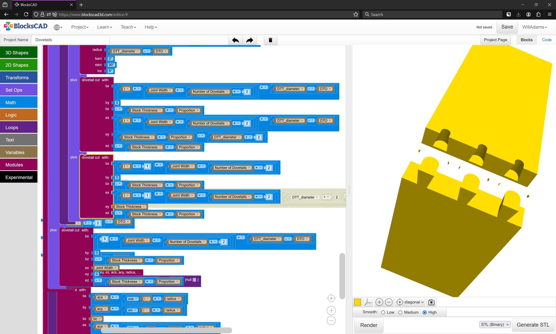
Adding the toolpath in BlockSCAD is a matter of a series of Hull() operations using the Dovetail tool at each end.
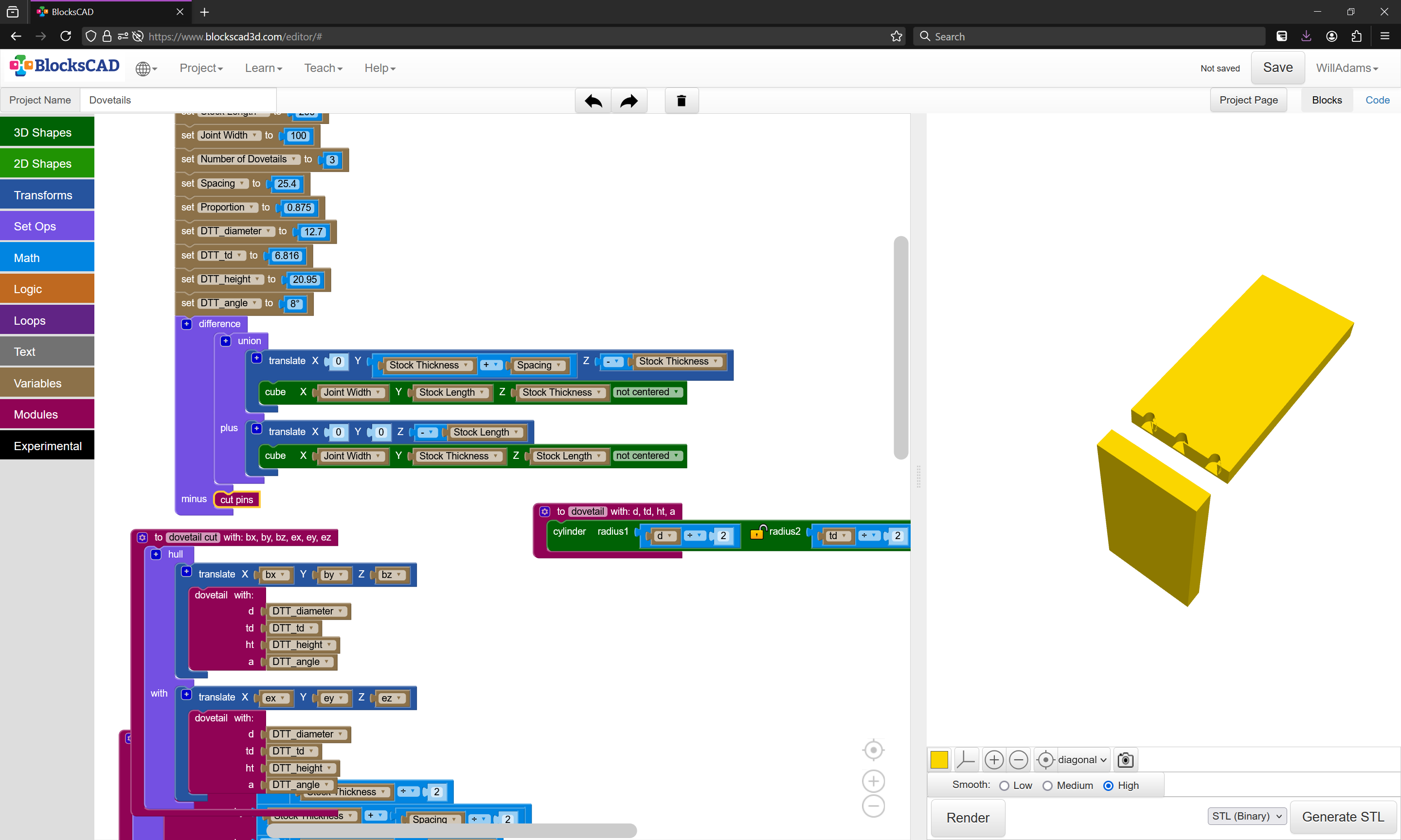
The flat cut is simplest, since it can be done using straight lines, so we set the Proportion variable:
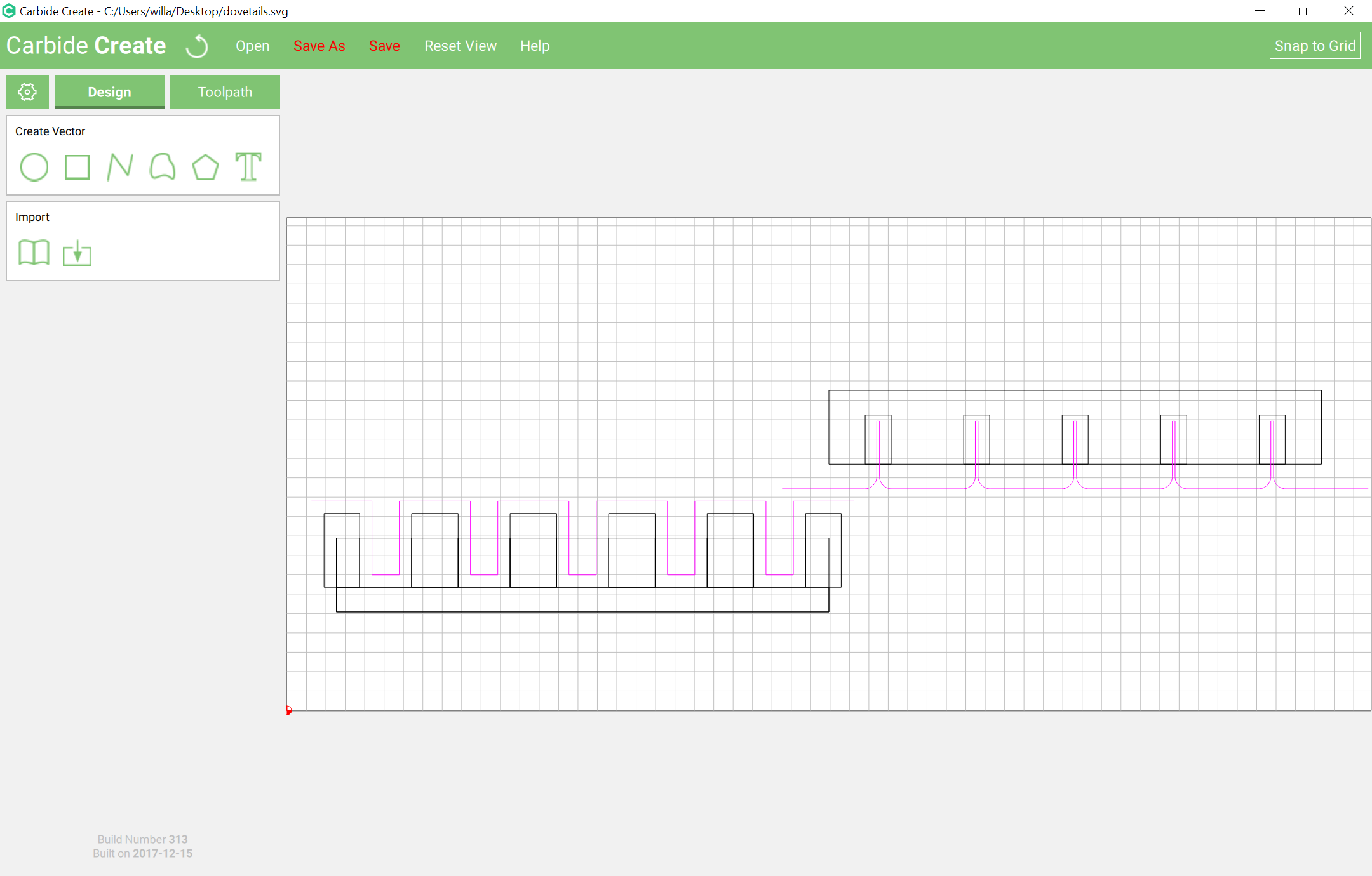
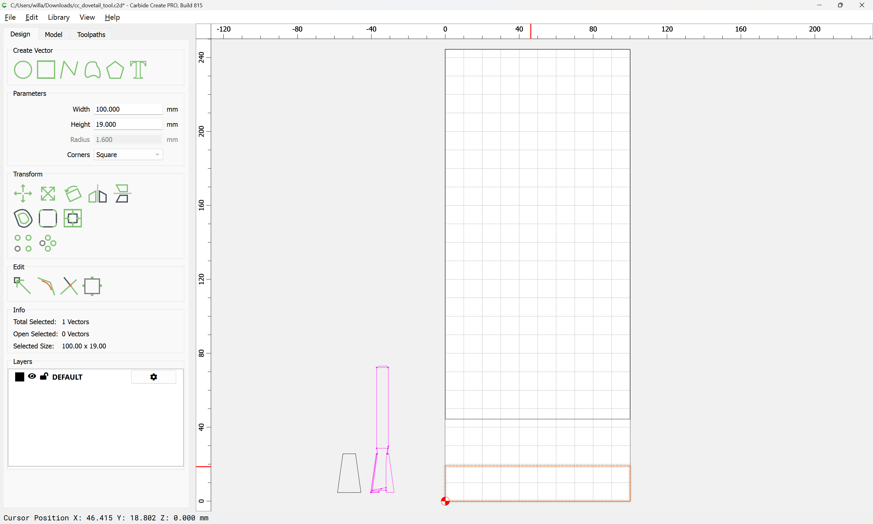
and then switch to Carbide Create draw up the same.
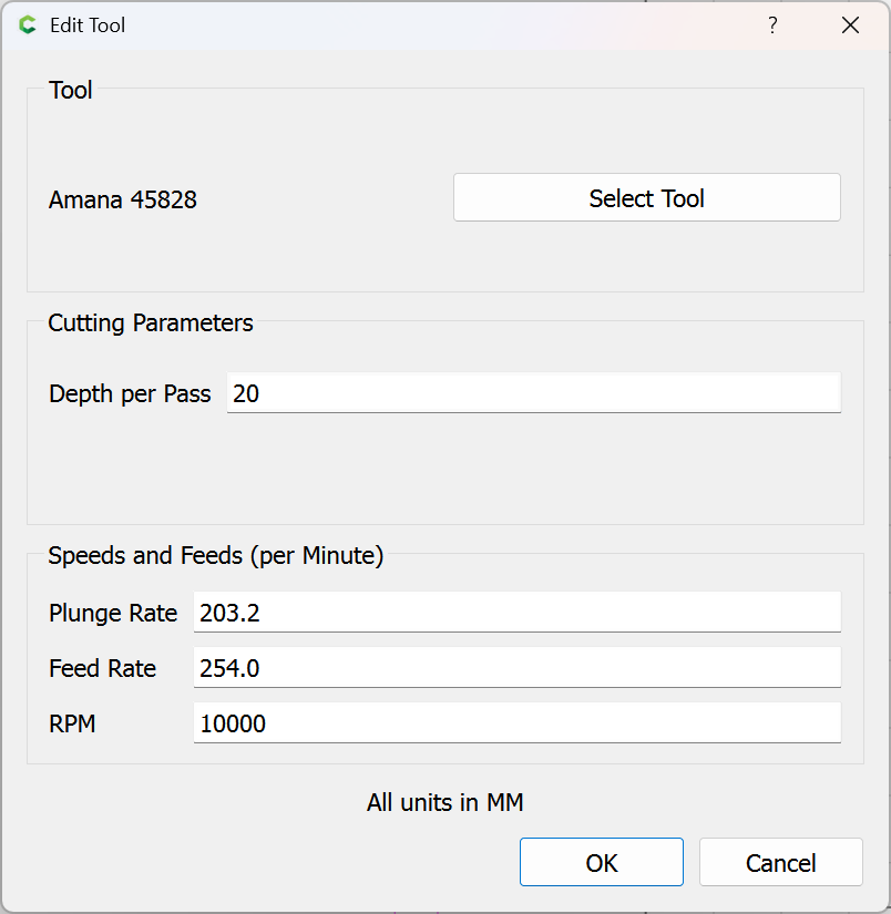
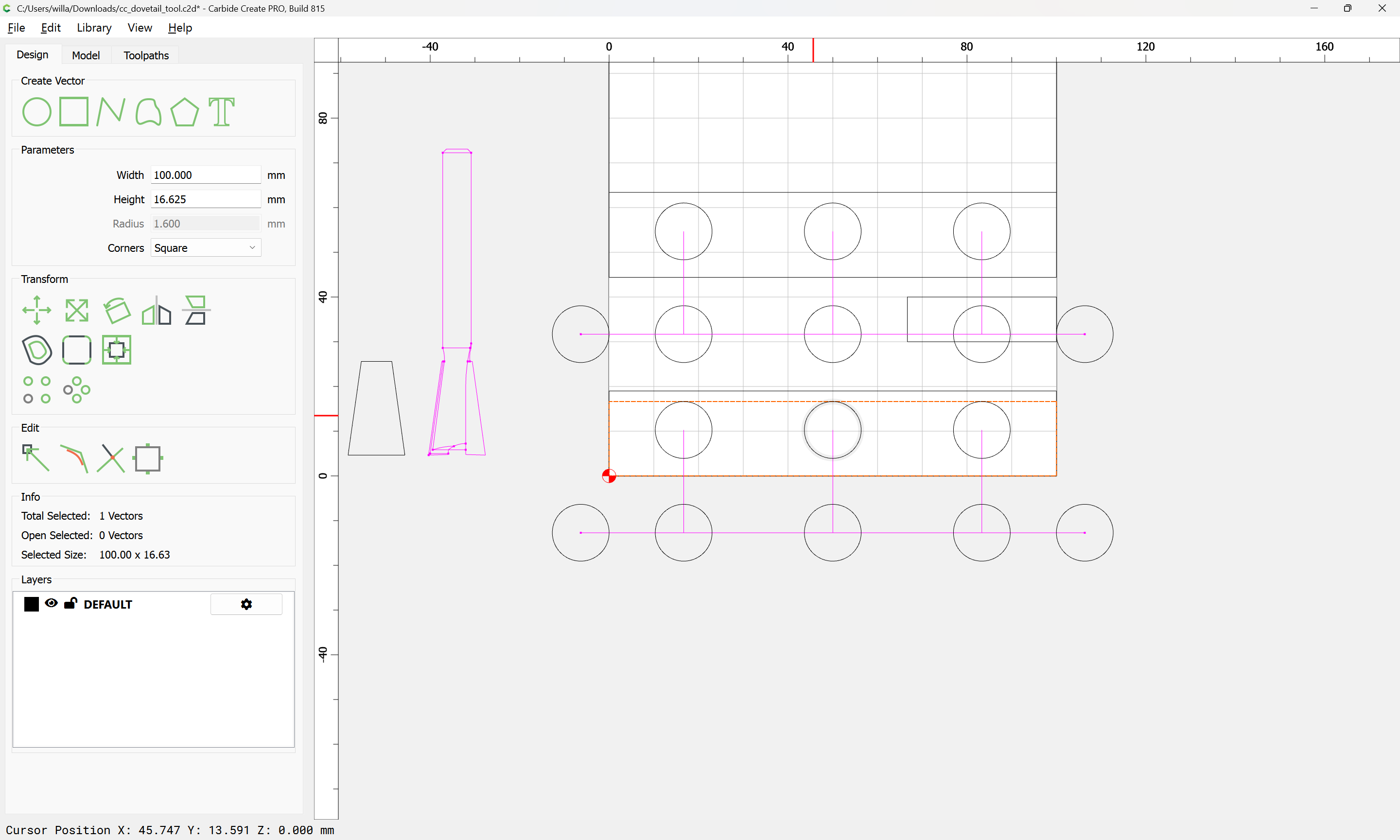
and define the tool:
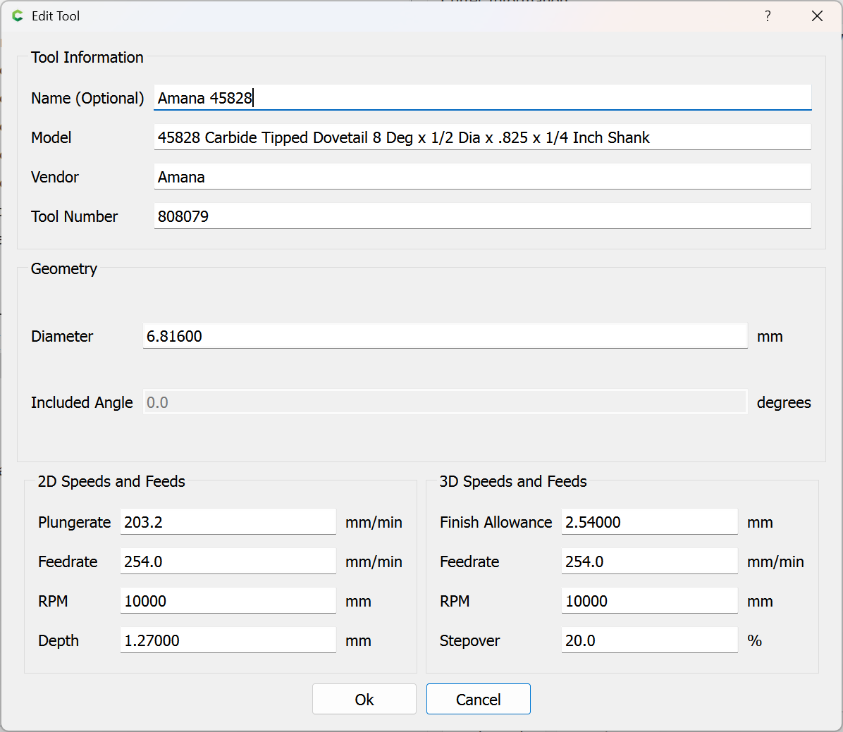
Note that the top diameter is used (the widening cut will need to be taken on faith, but this way we can get an accurate preview of the cut at the surface).
Then draw in geometry for each of the parts:
Then draw in the toolpath — there are supposed to be 3 Dovetails:
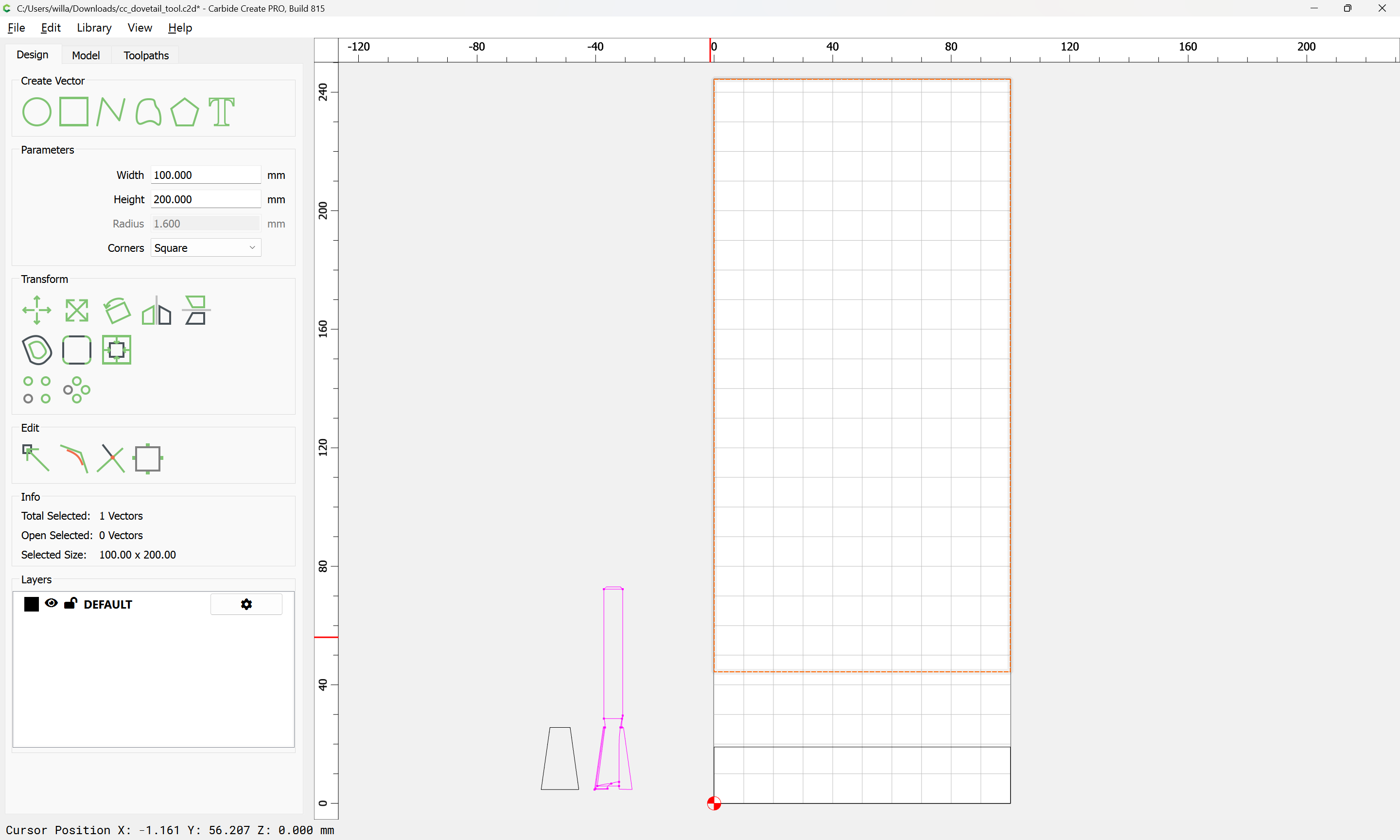
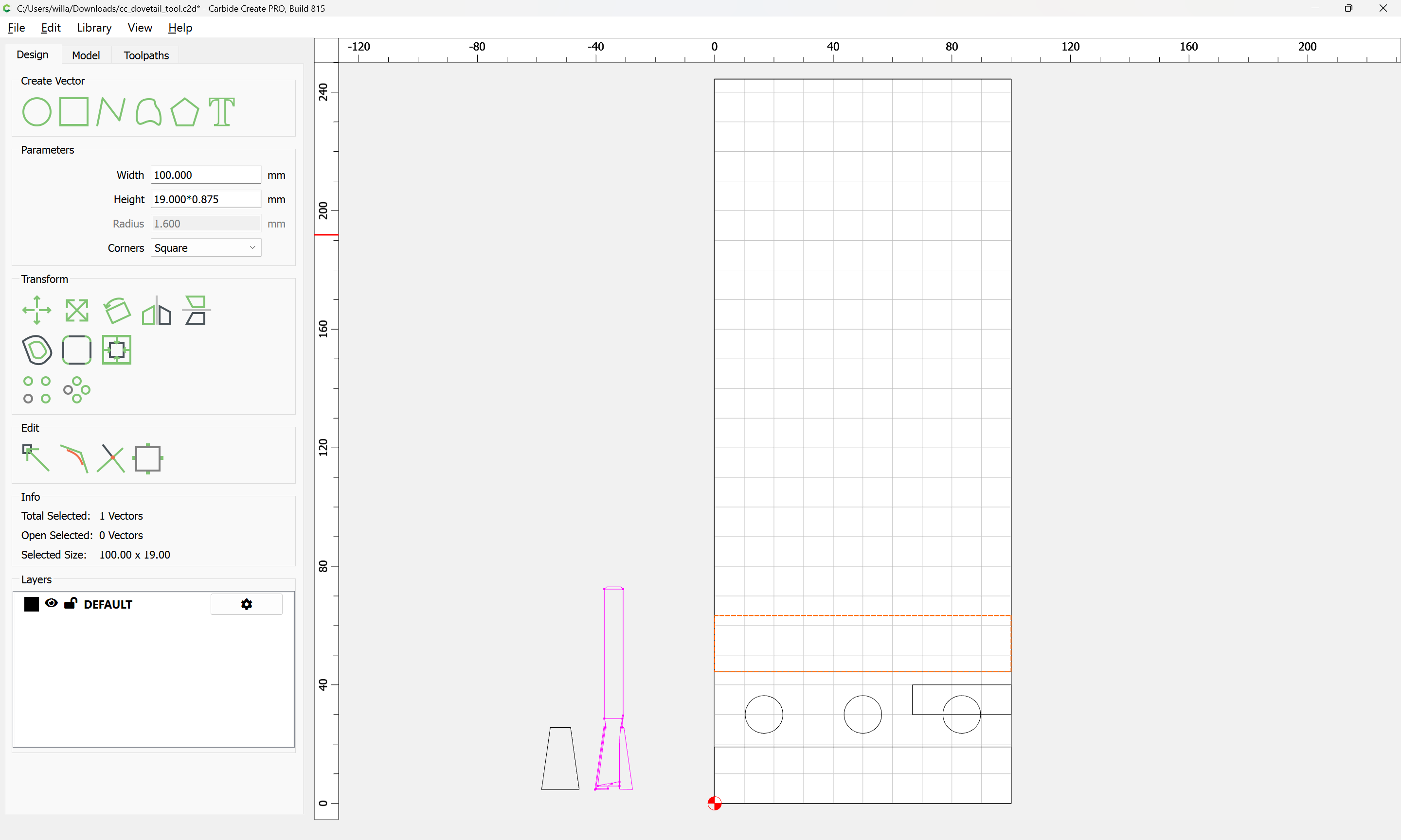
Draw in a rectangle:
Then divide it by the number of dovetails:
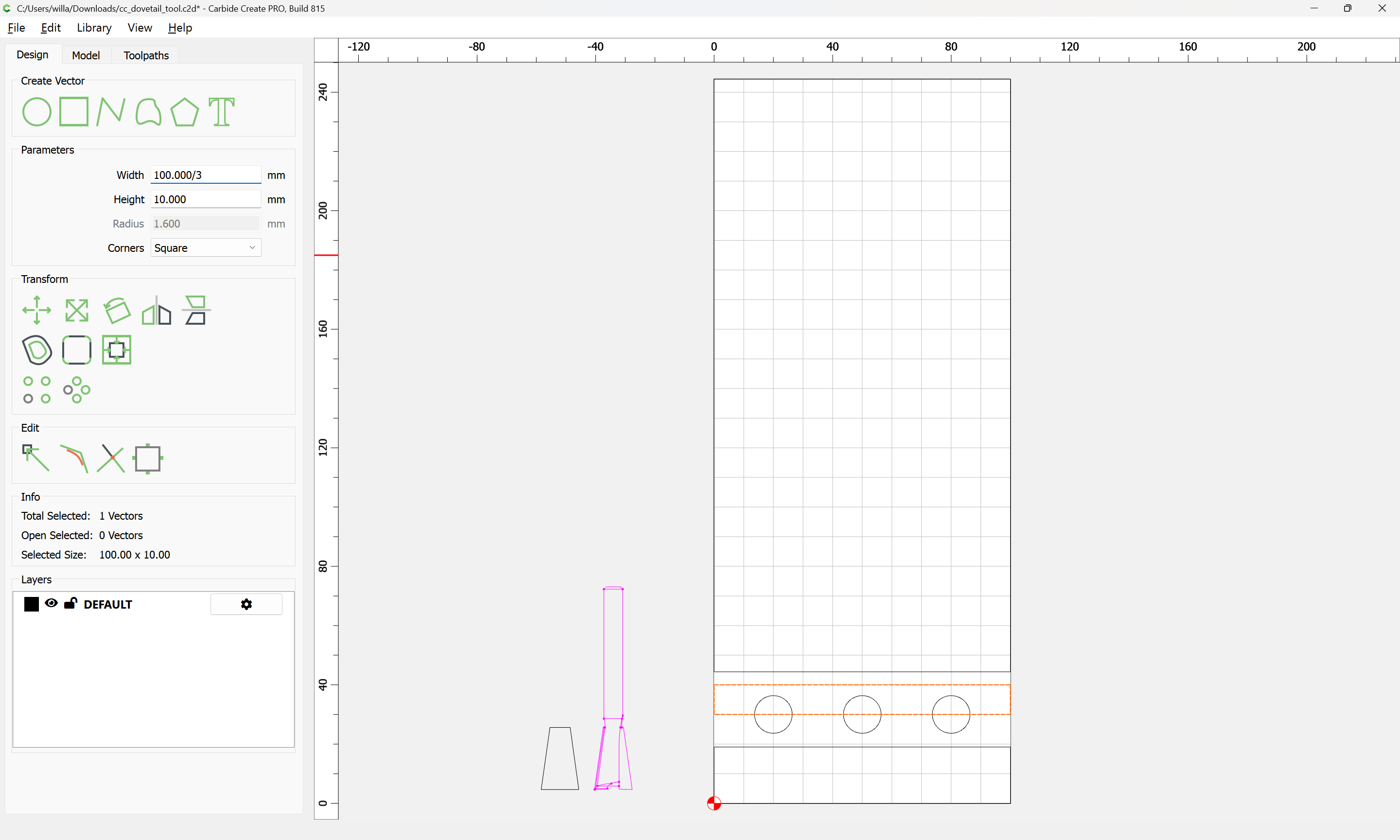
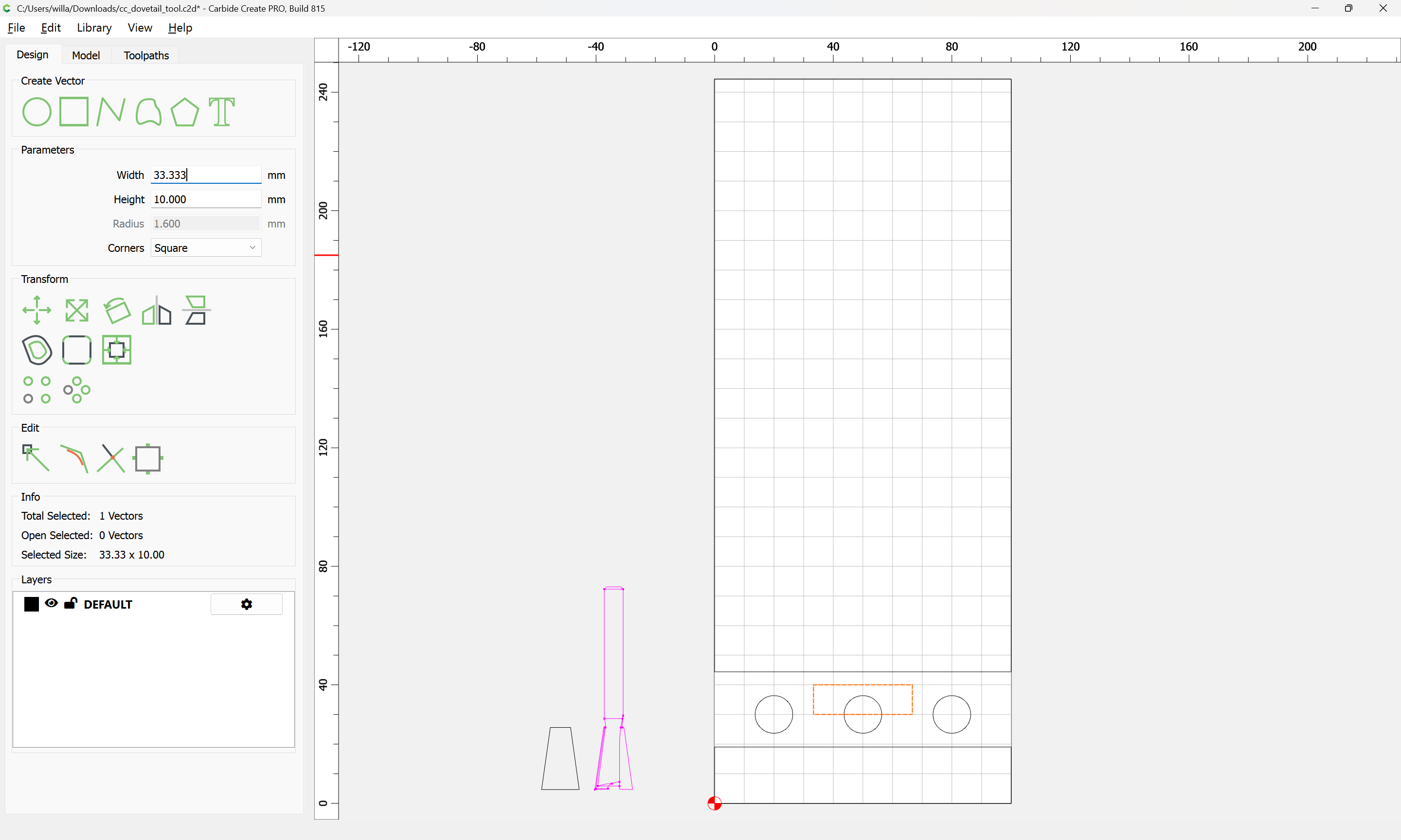
and use it to set the spacing:
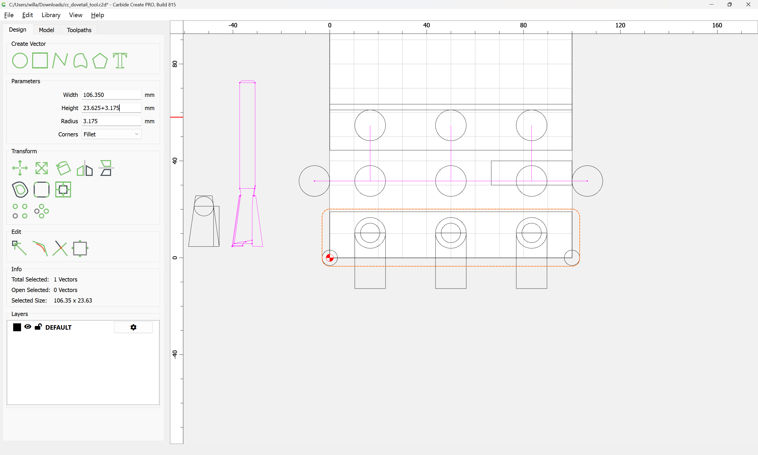
Then we draw in a rectangle to show the Stock Thickness:
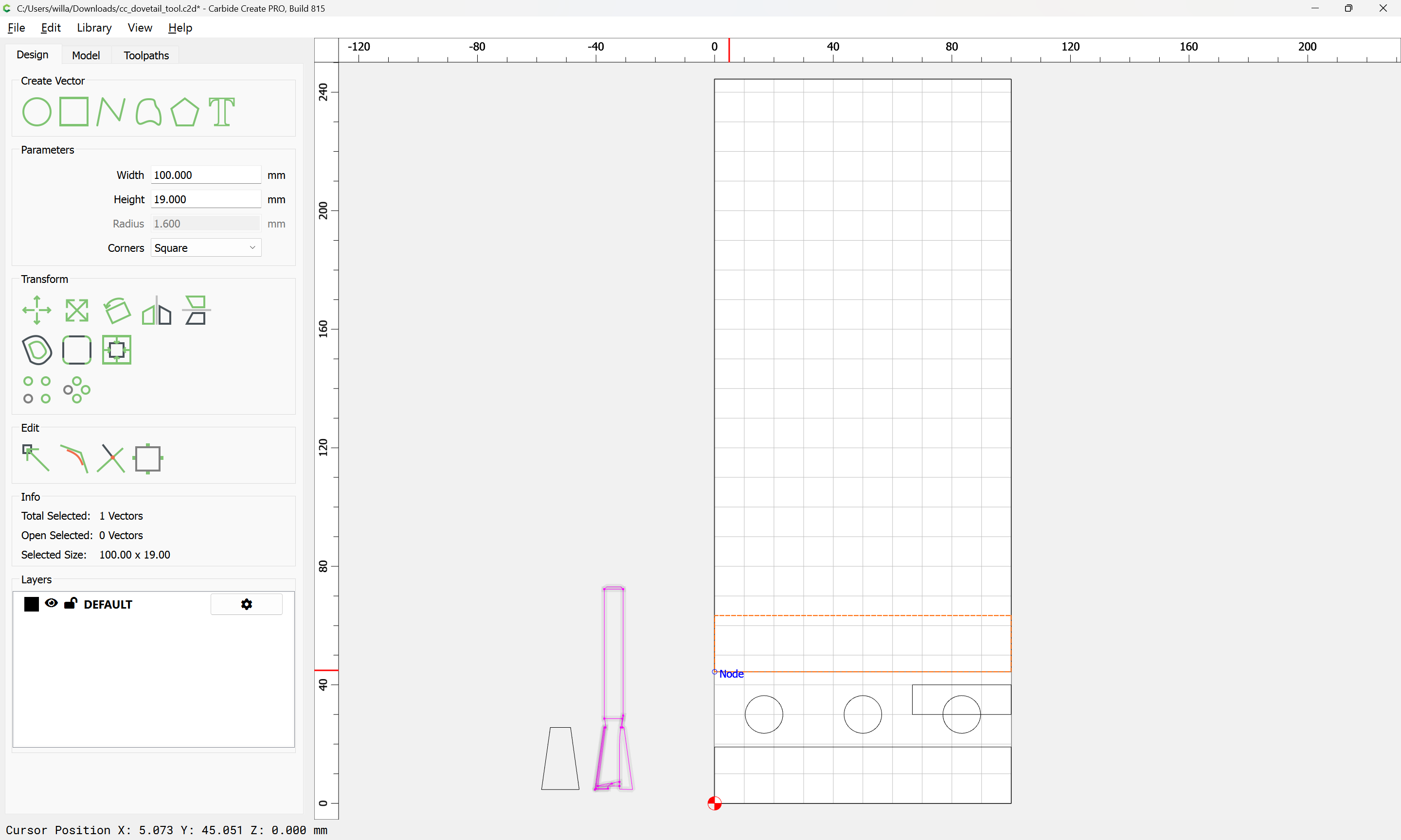
and scale it vertically by the Proportion:
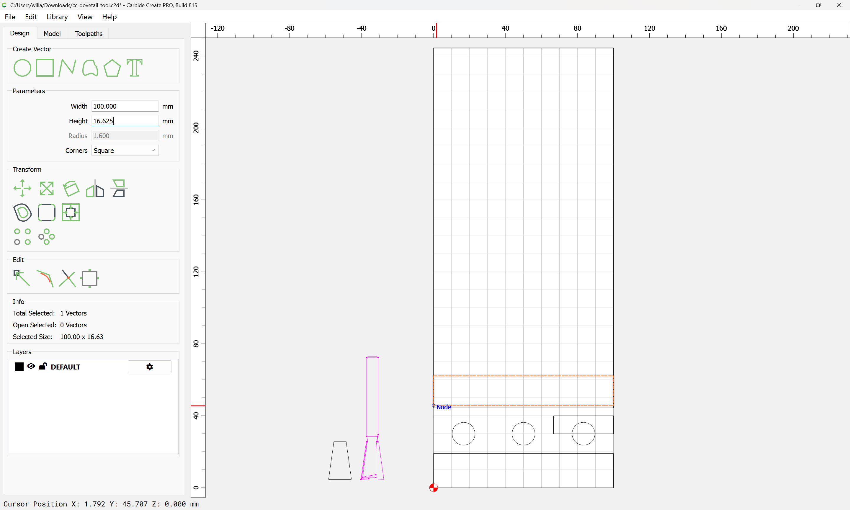
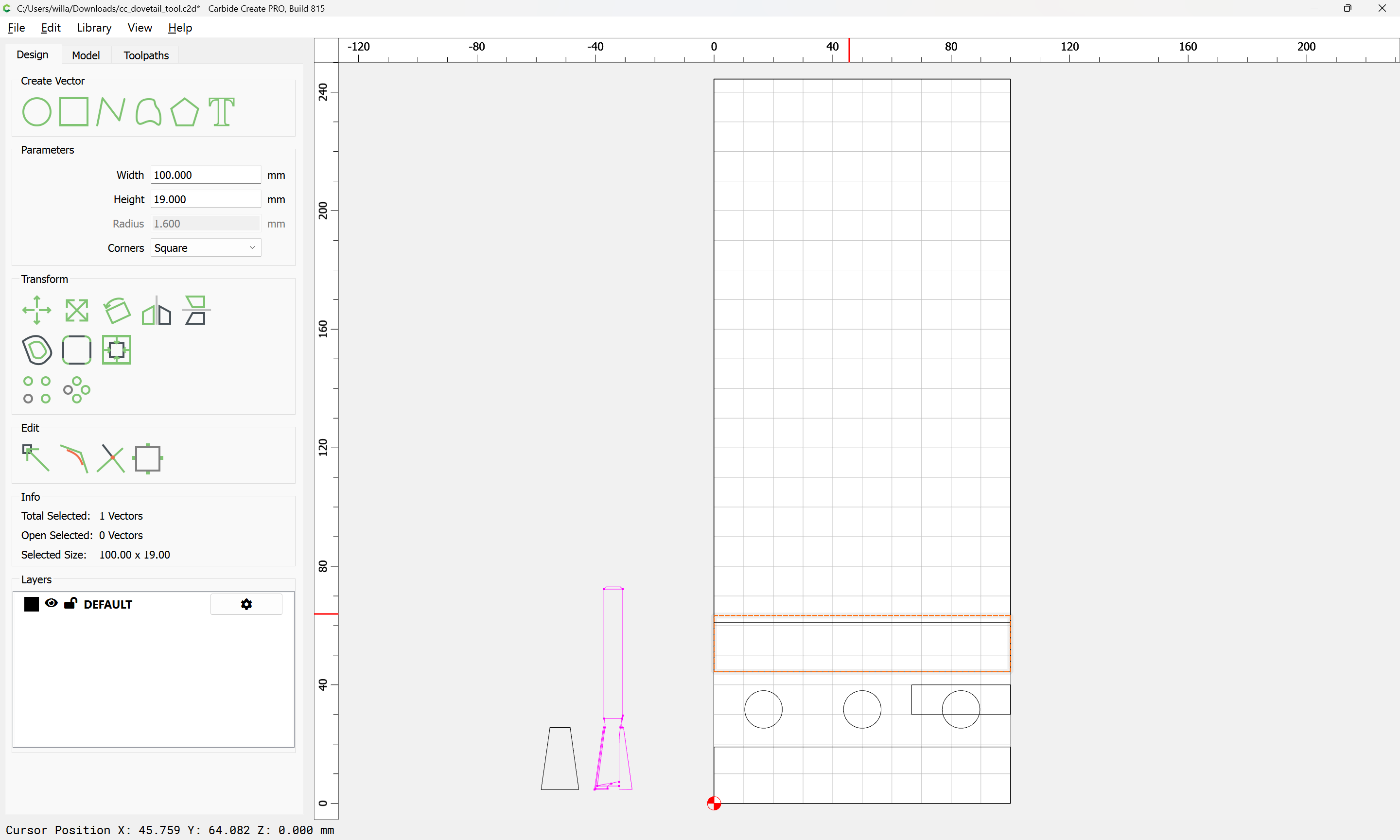
and reposition:

and restore:
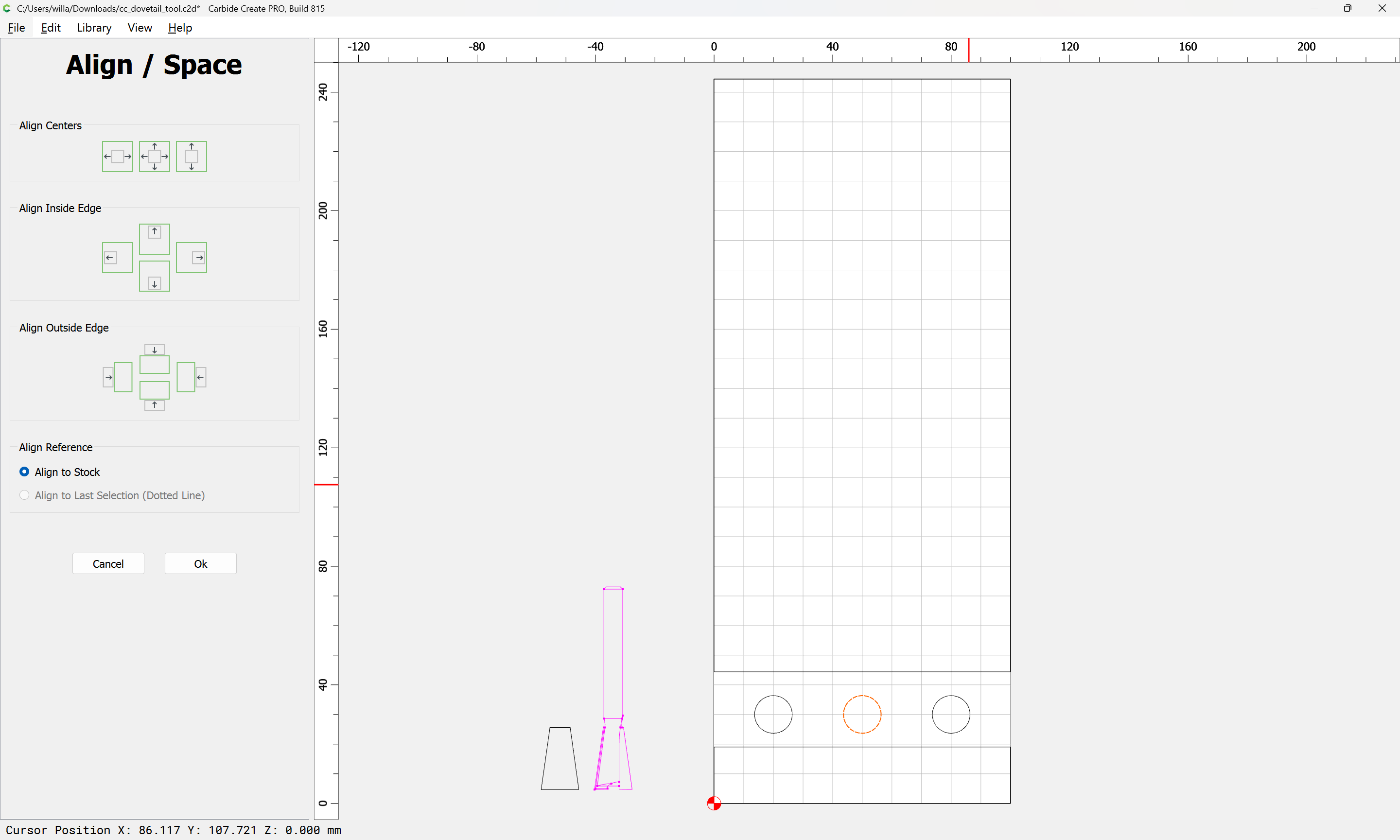
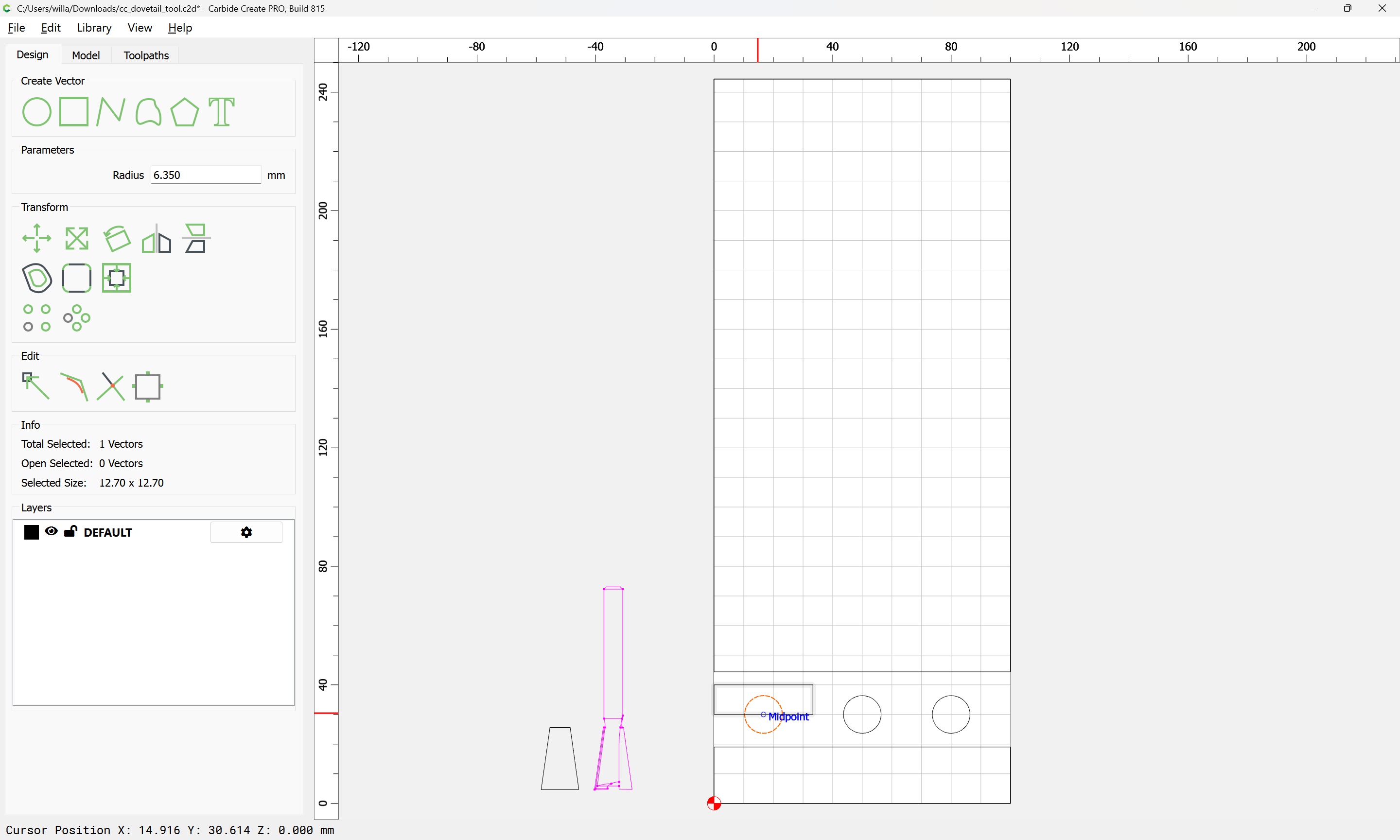
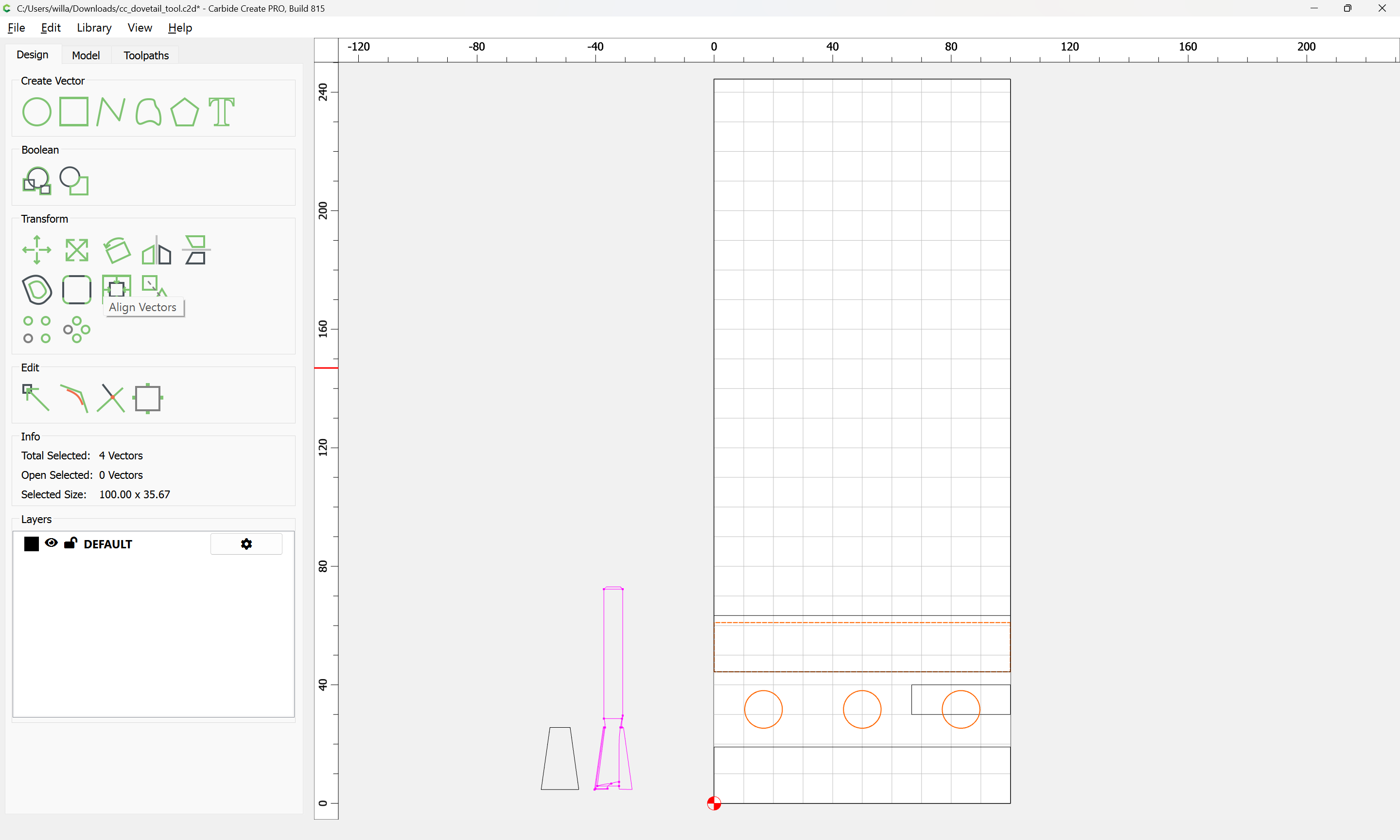
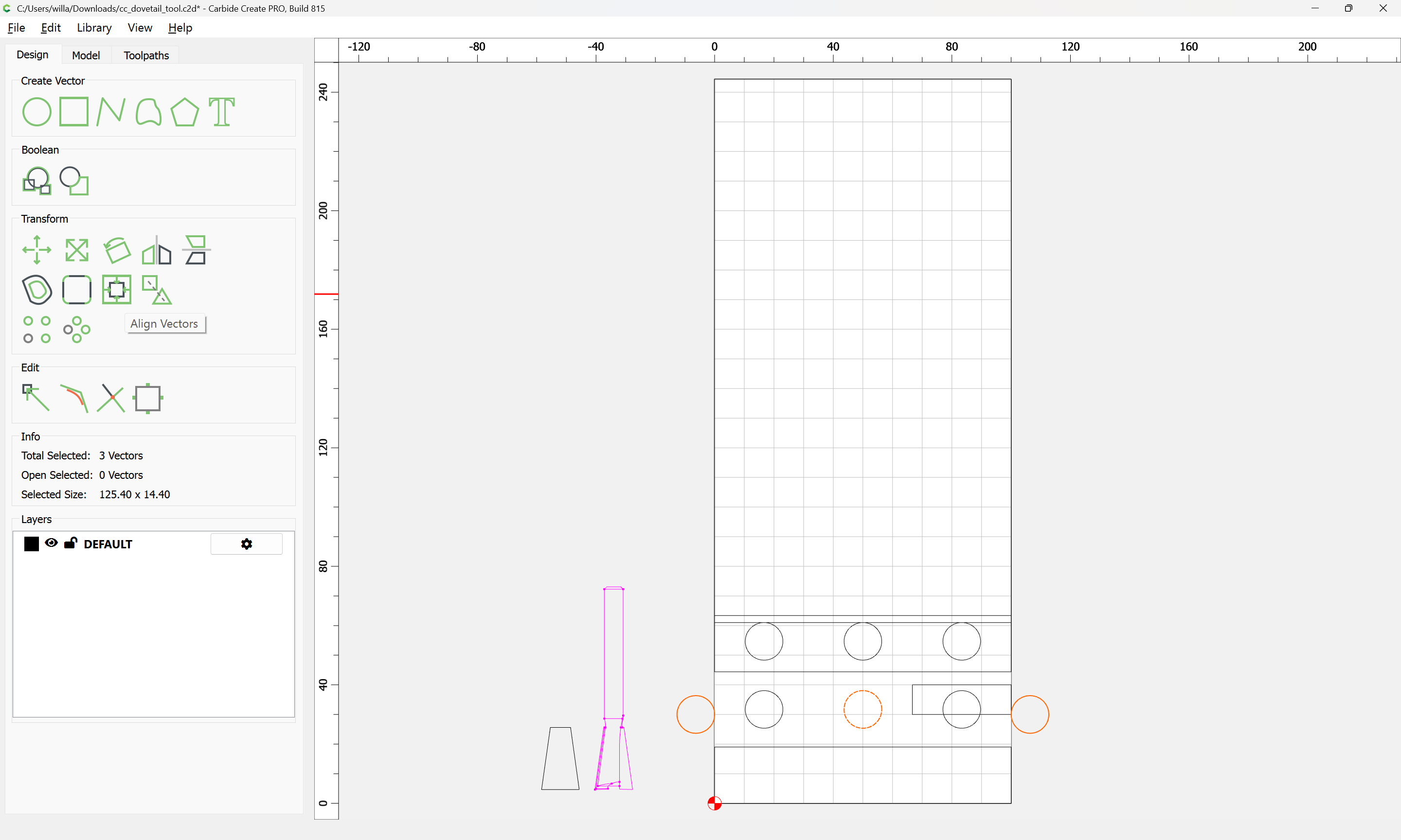
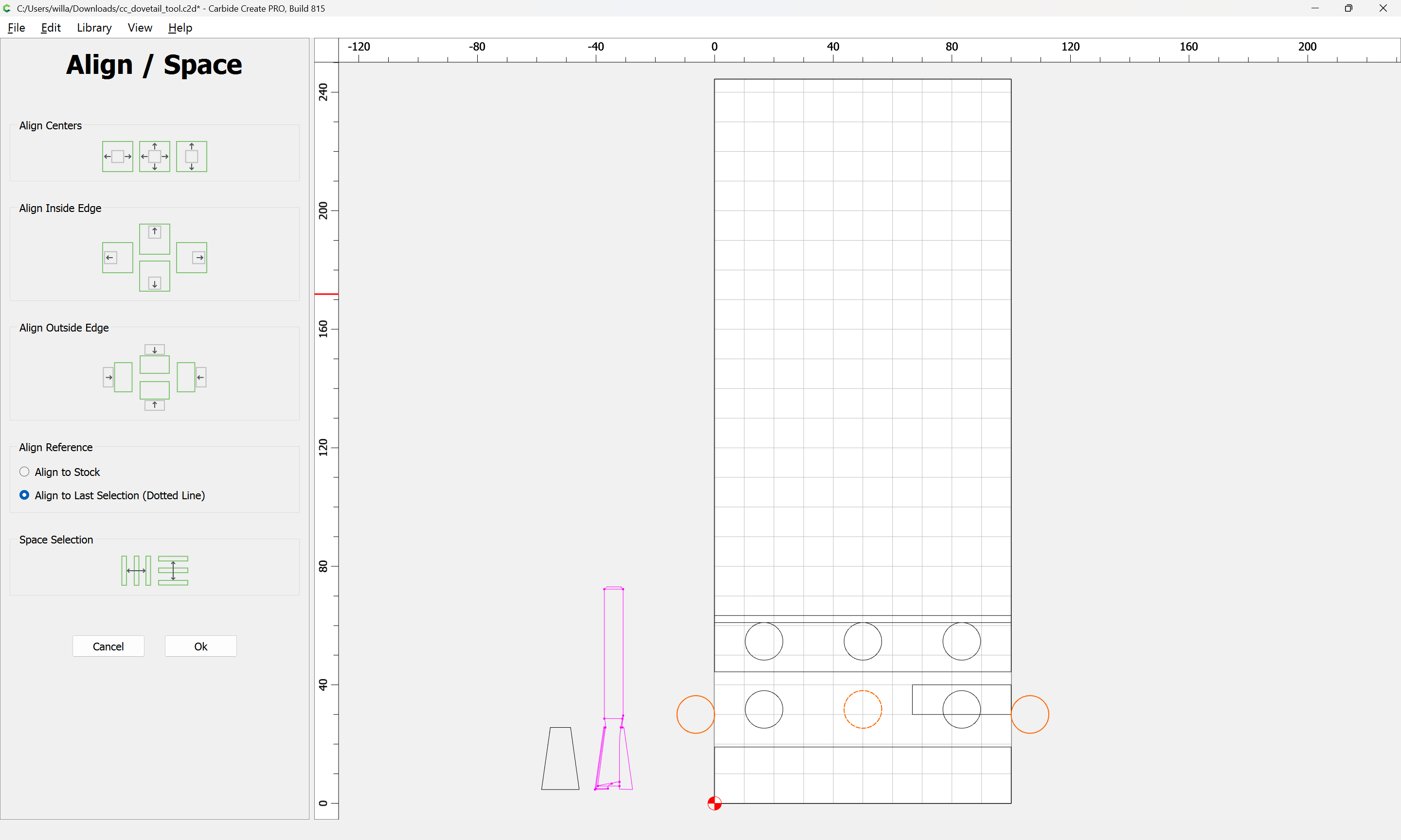
Select and duplicate the circles:
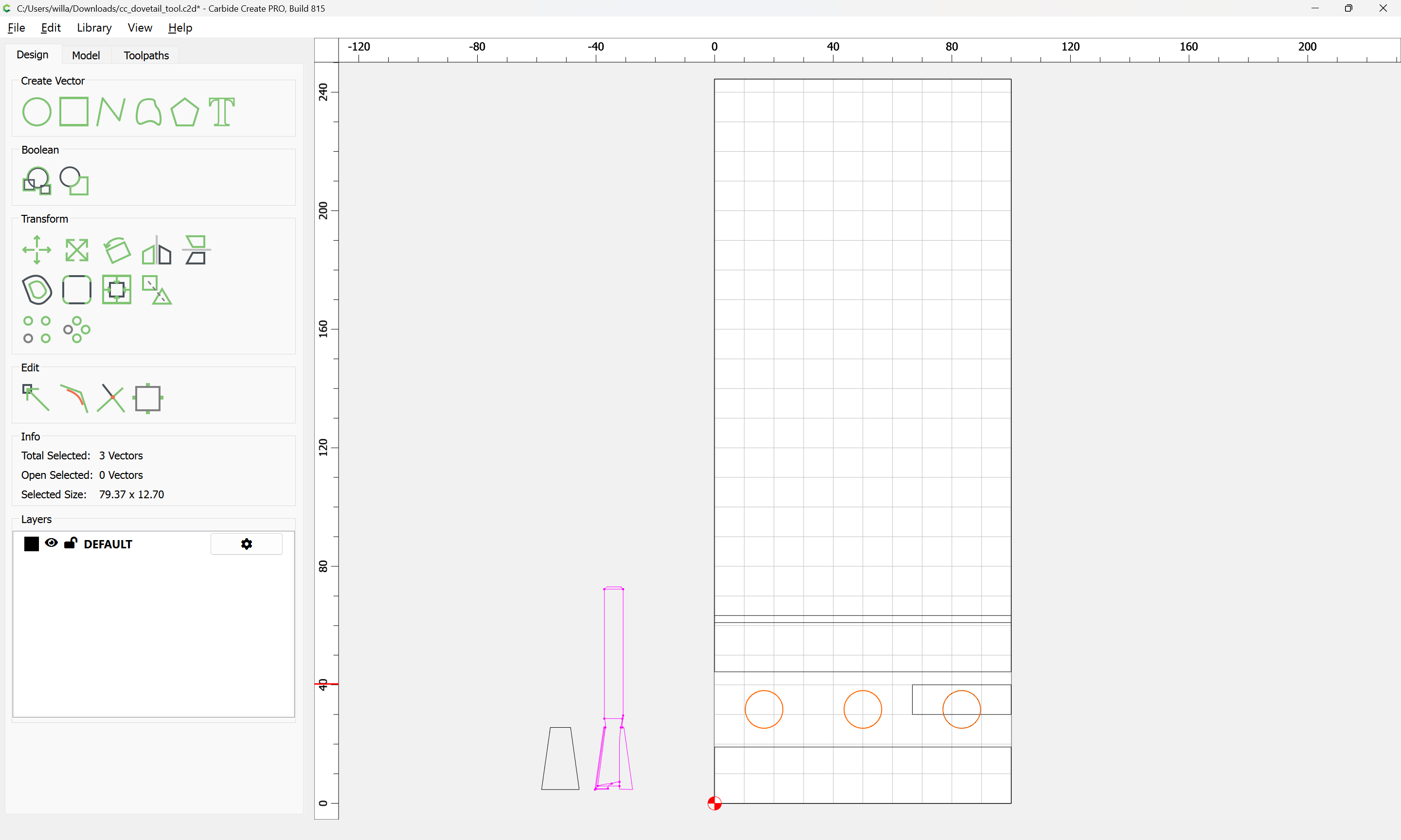
and align them against the scaled rectangle:

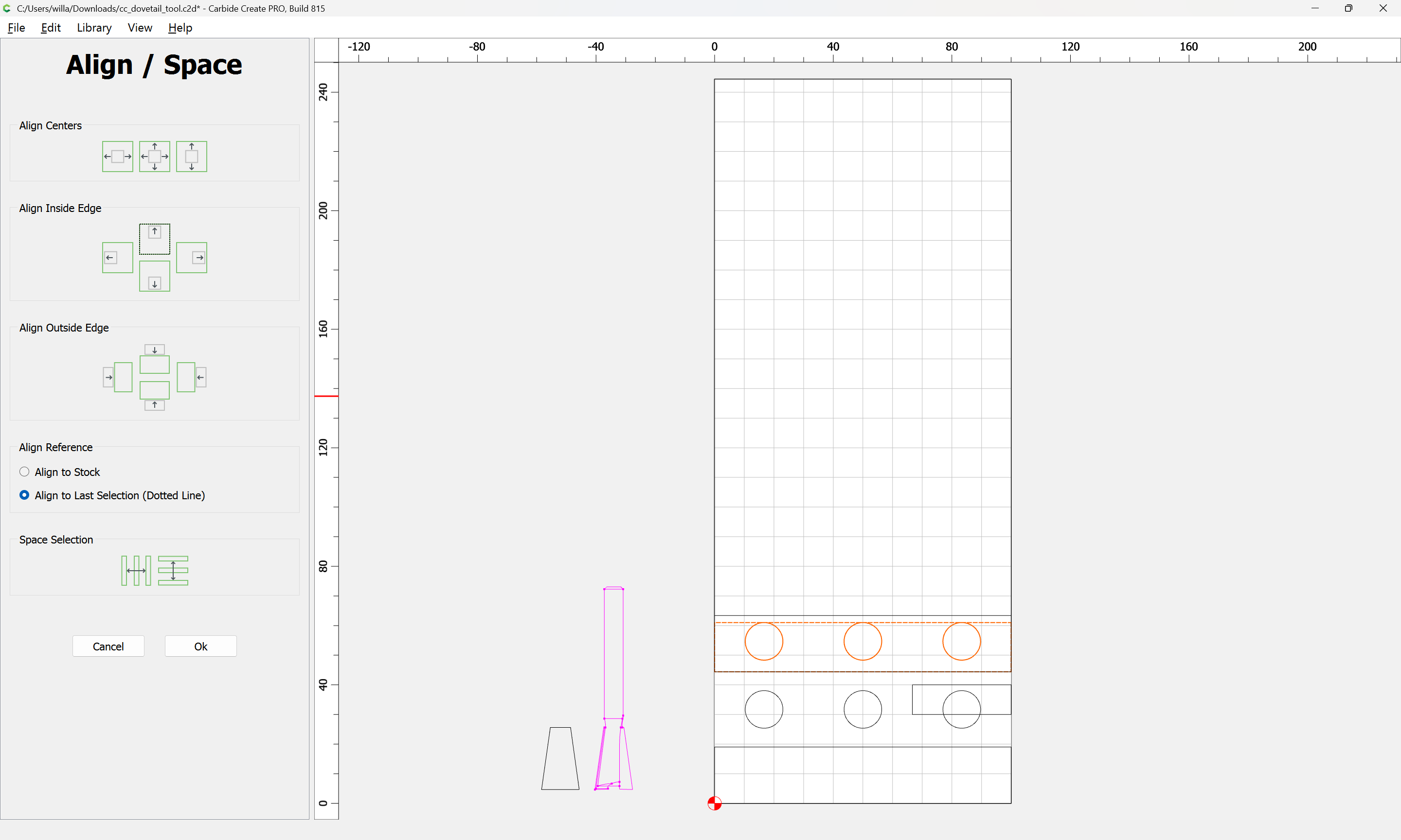
Ok

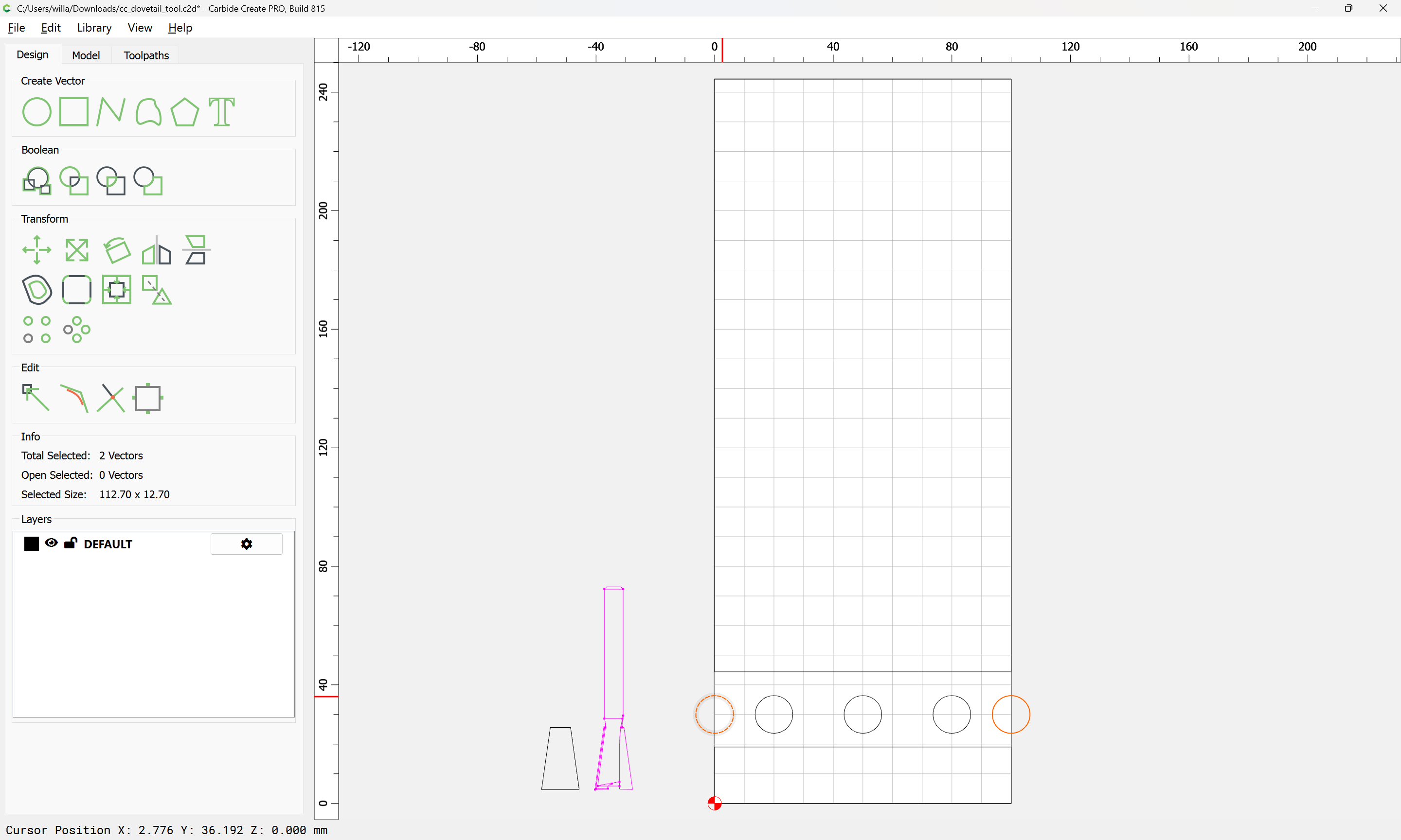
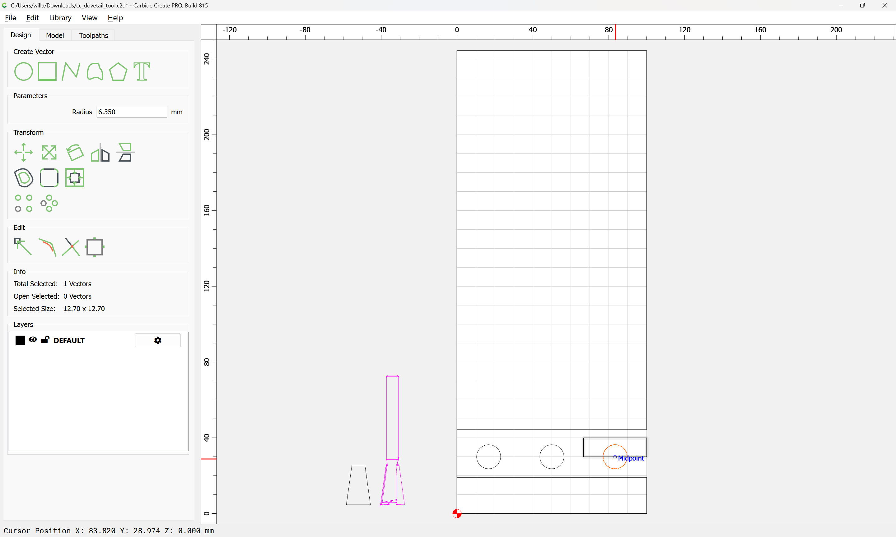
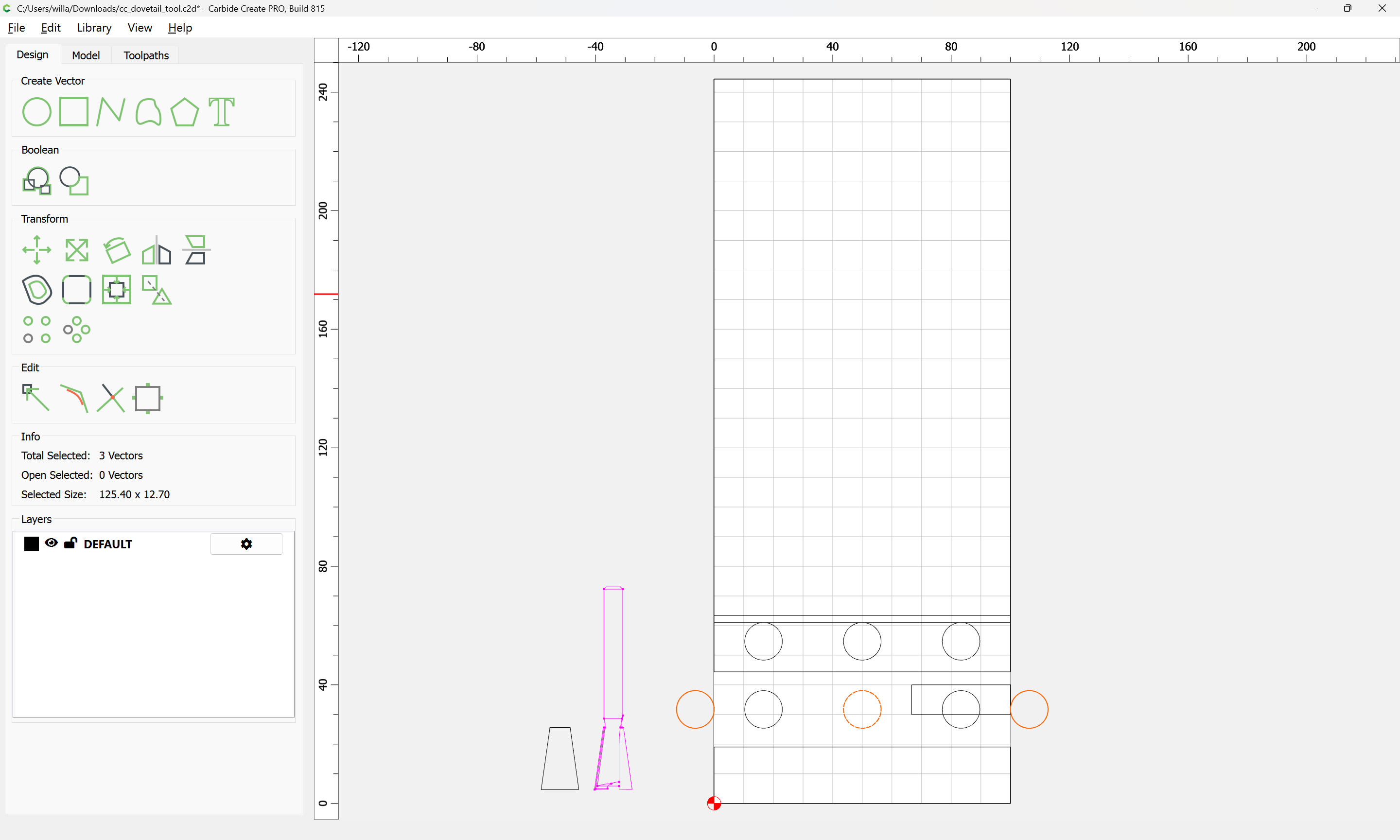
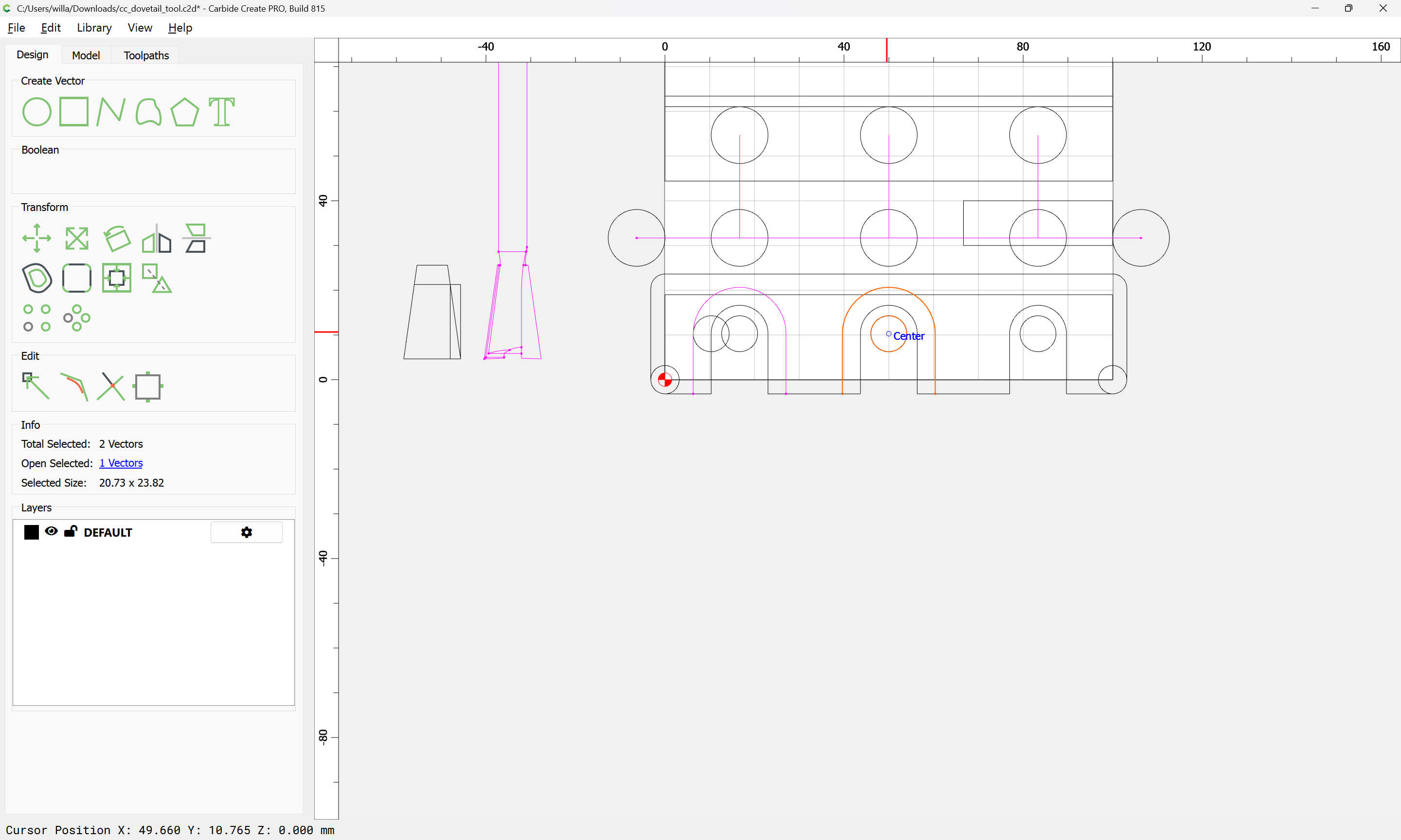
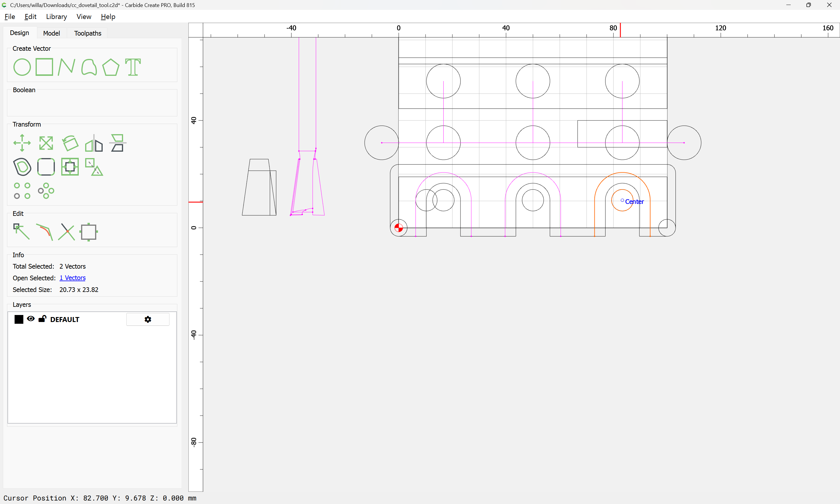
and then draw/position circles for begin/end:

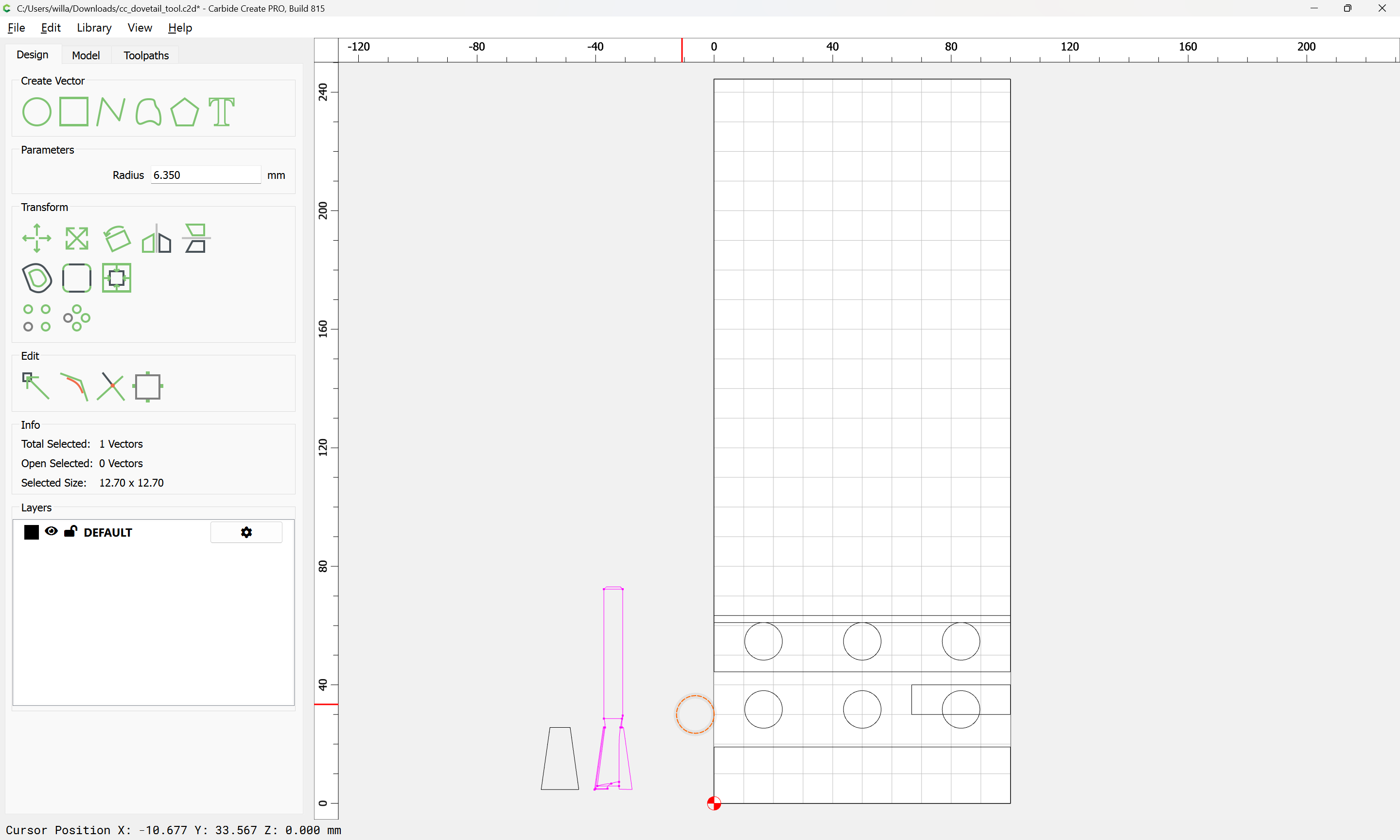
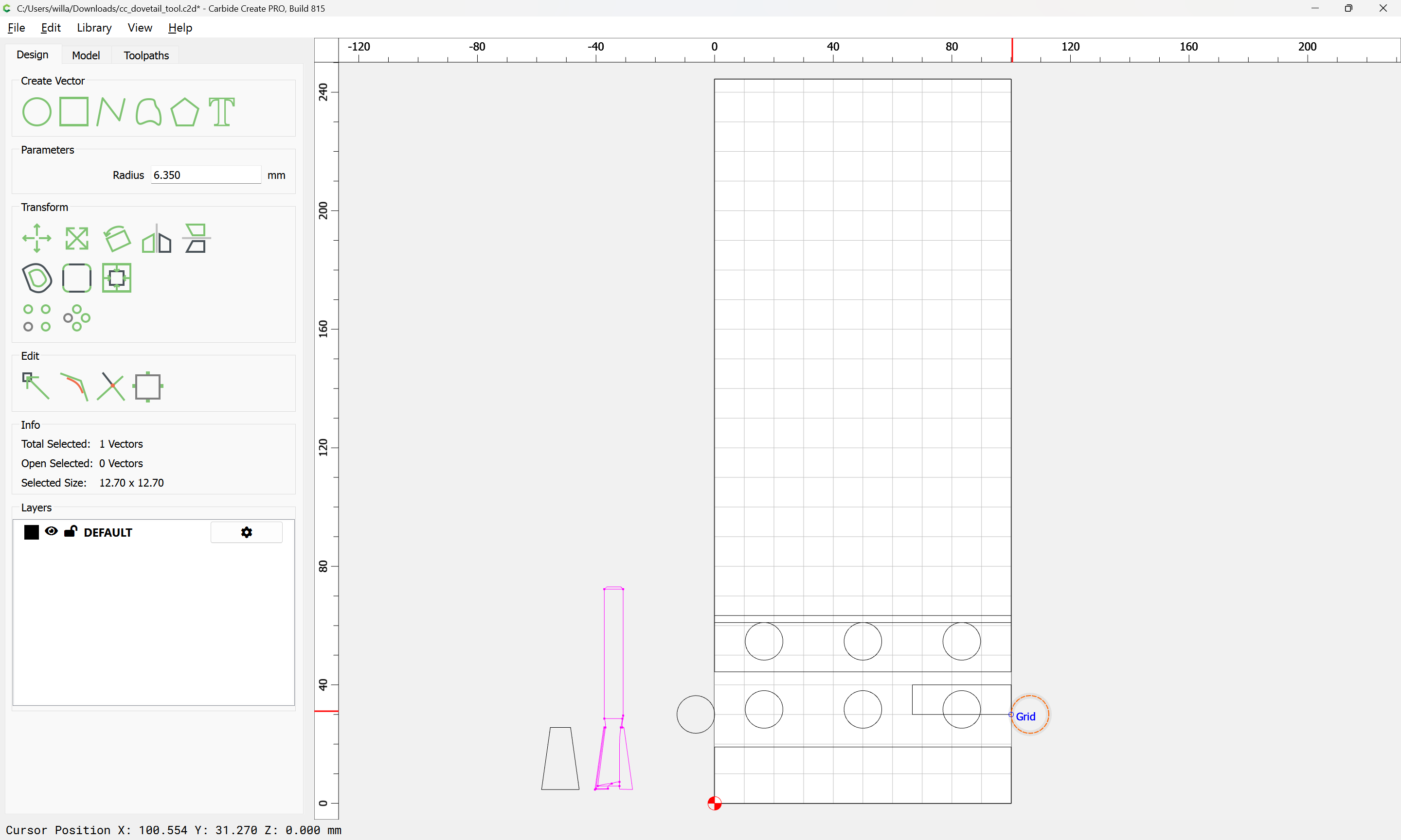
Ensuring that they are lined up:

Ok
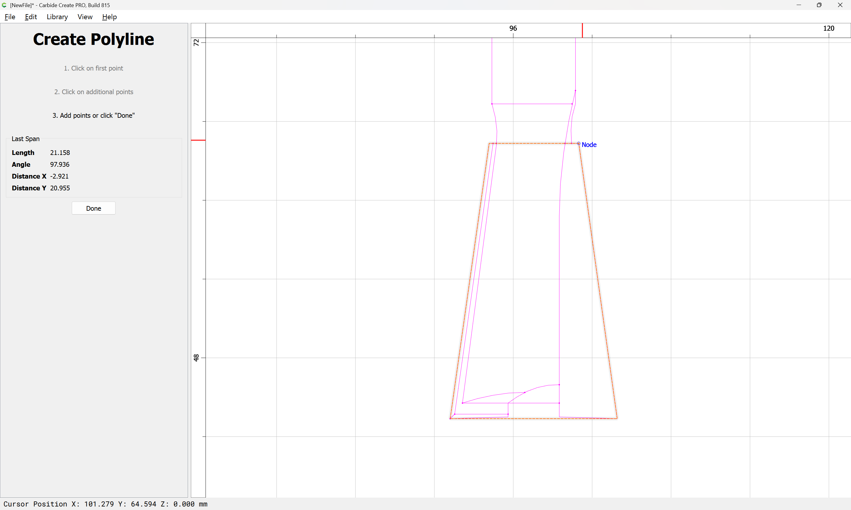
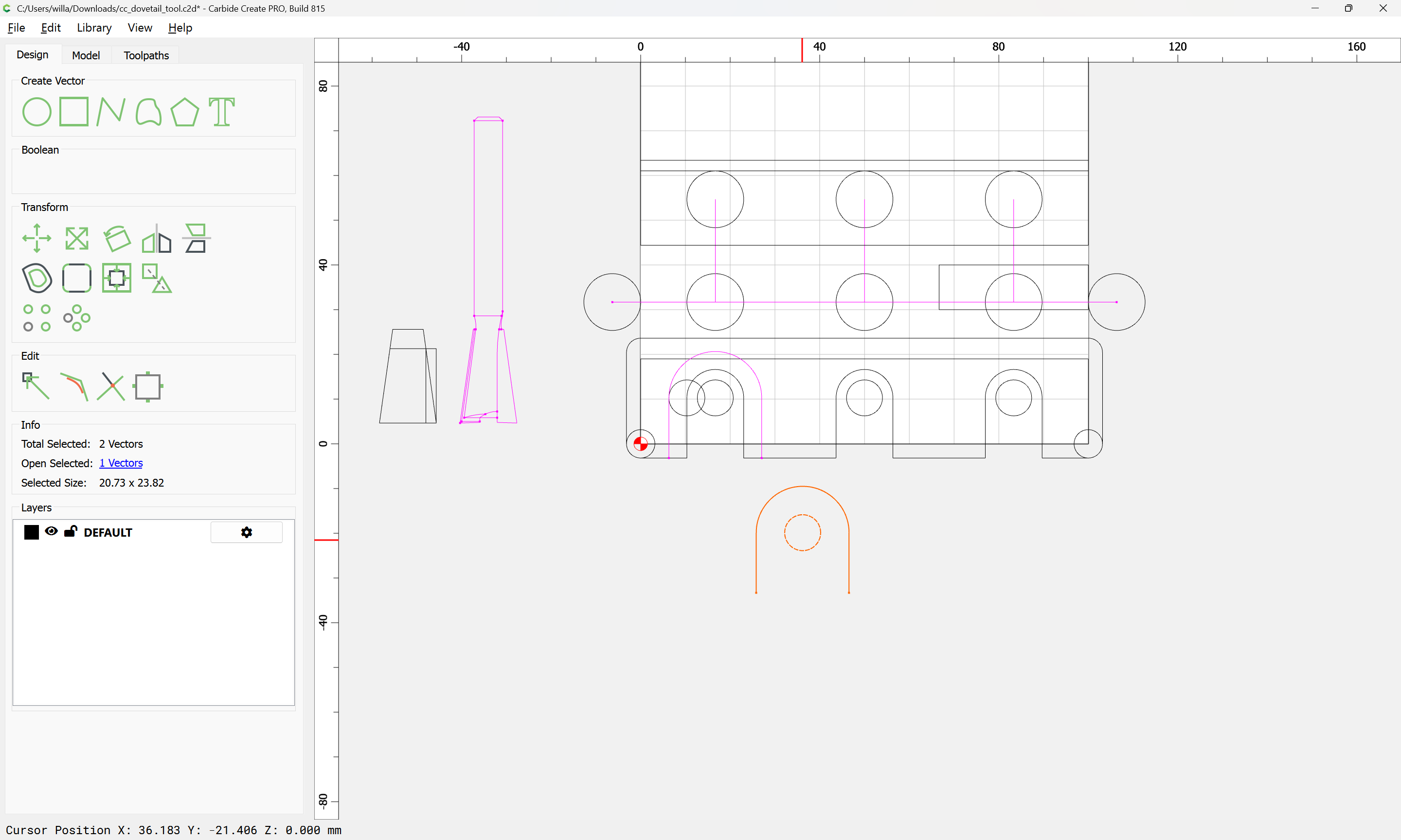
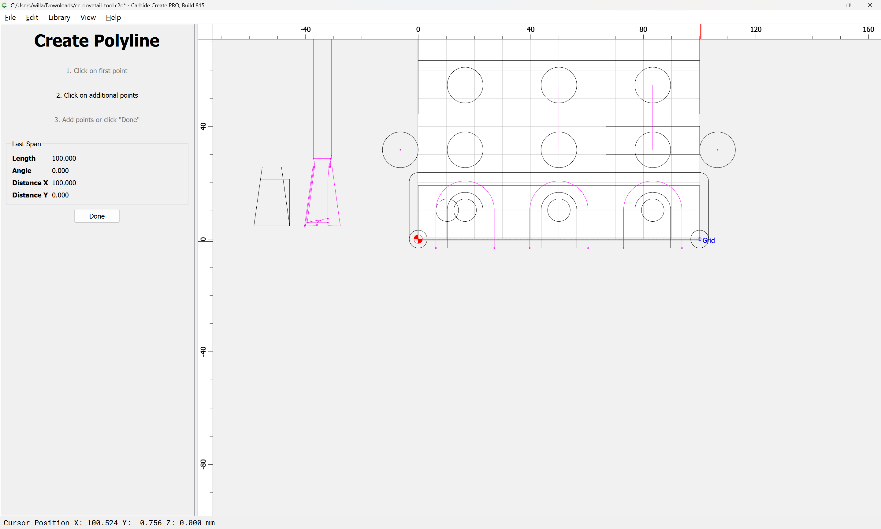
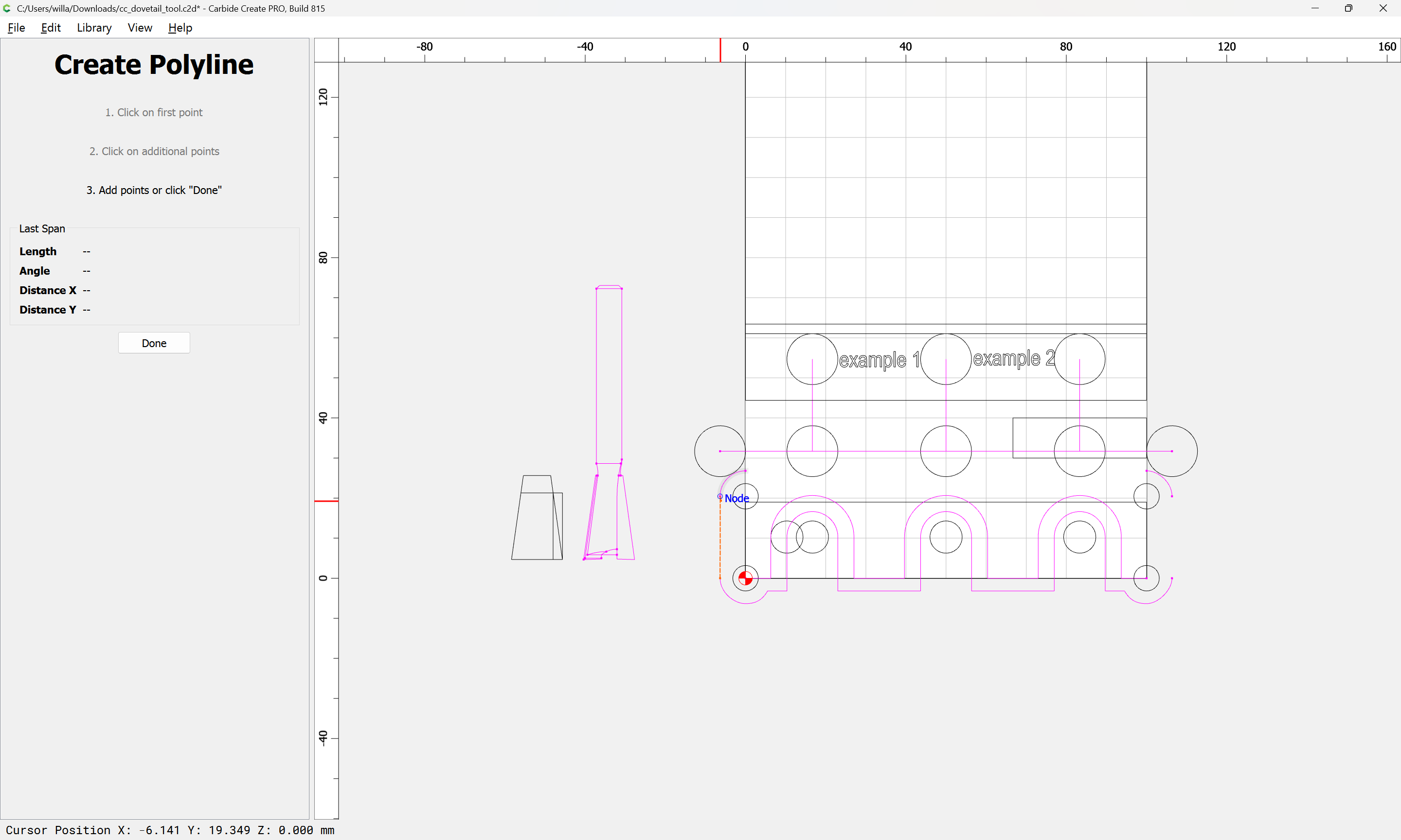
Then it is simply a matter of connecting the centers with a Polyline:
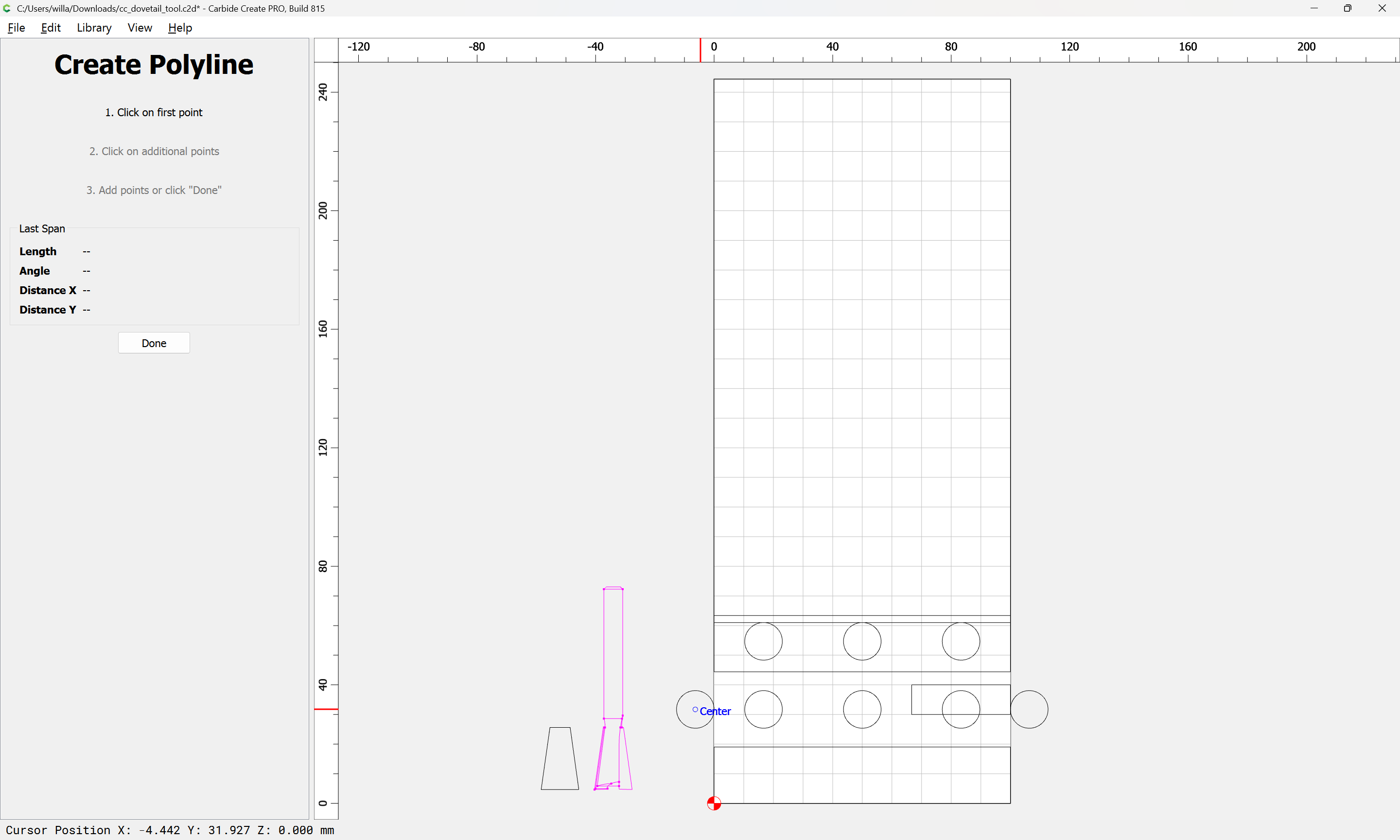

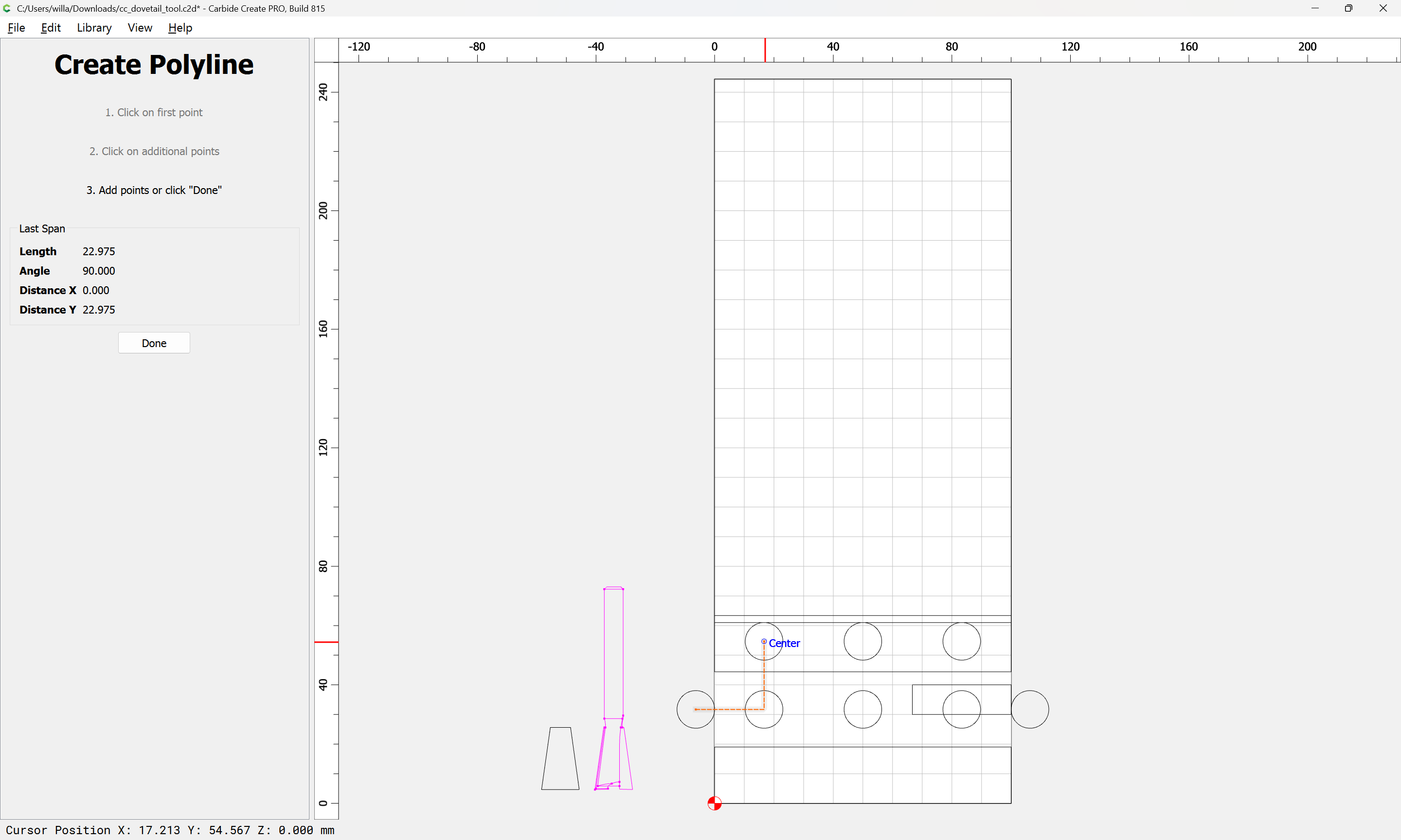
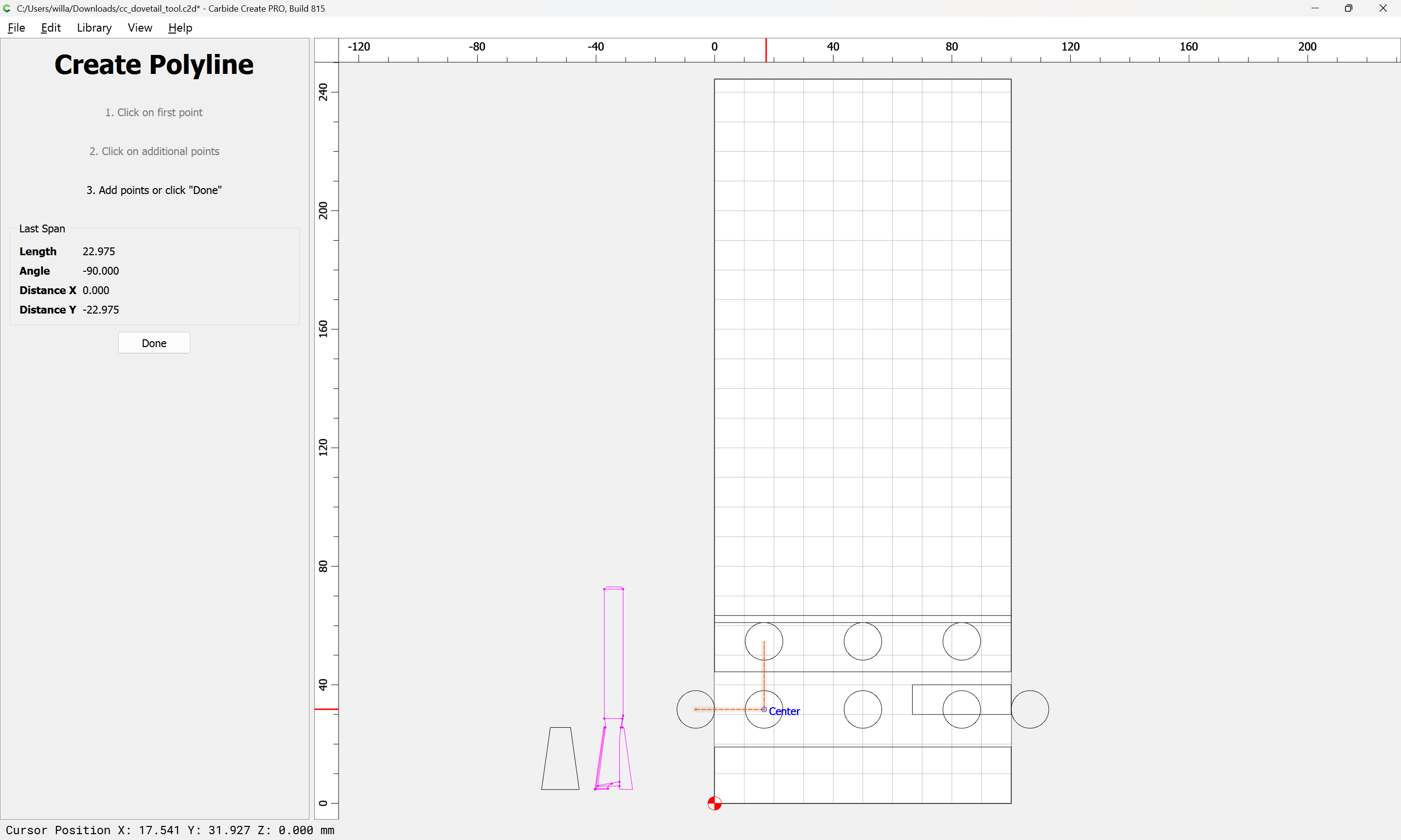
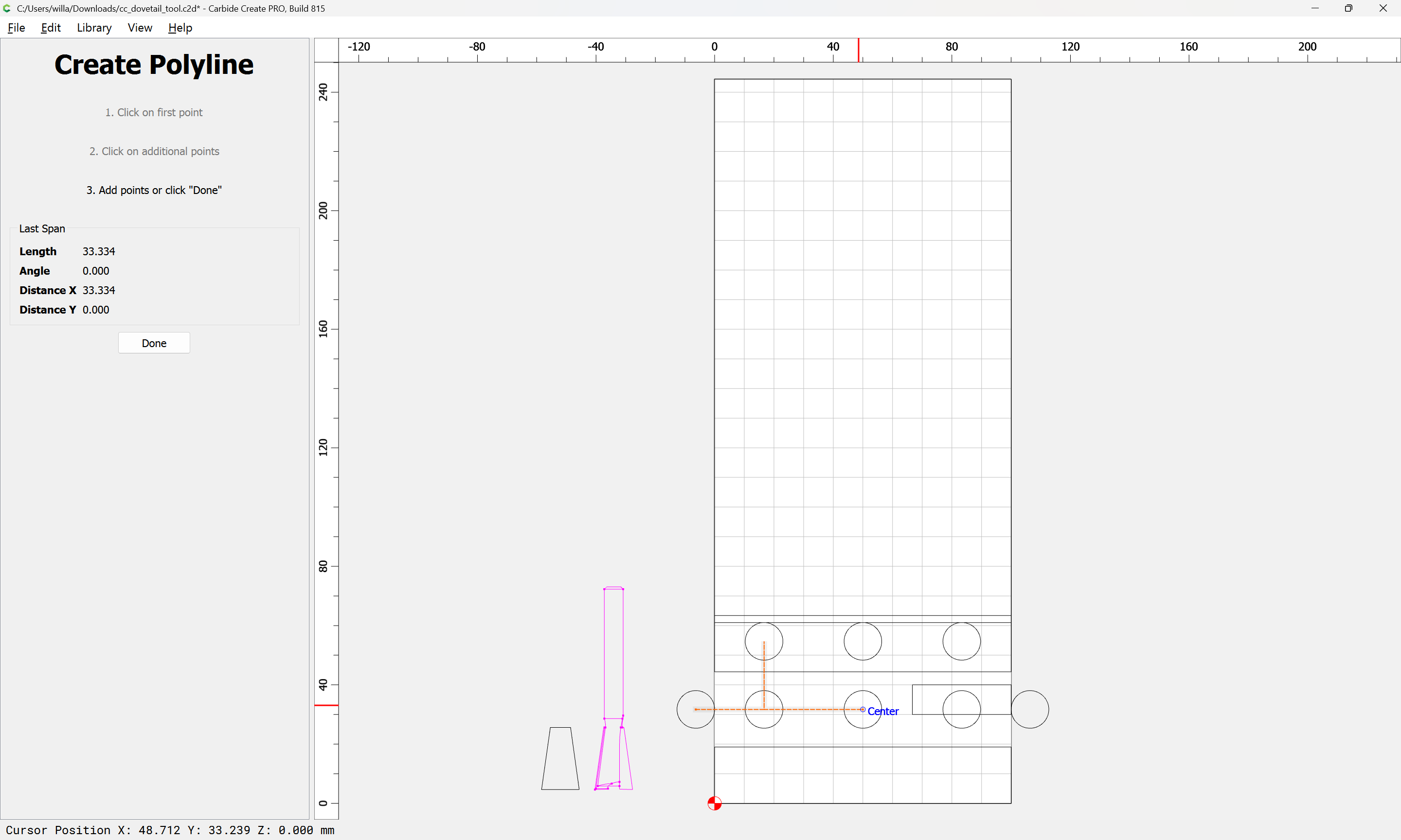
arriving at:
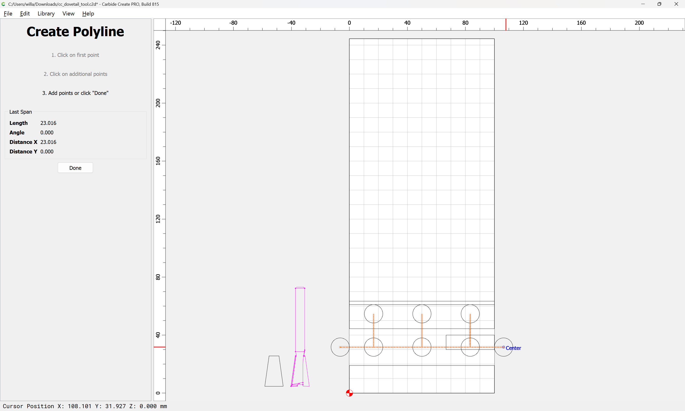
Ok
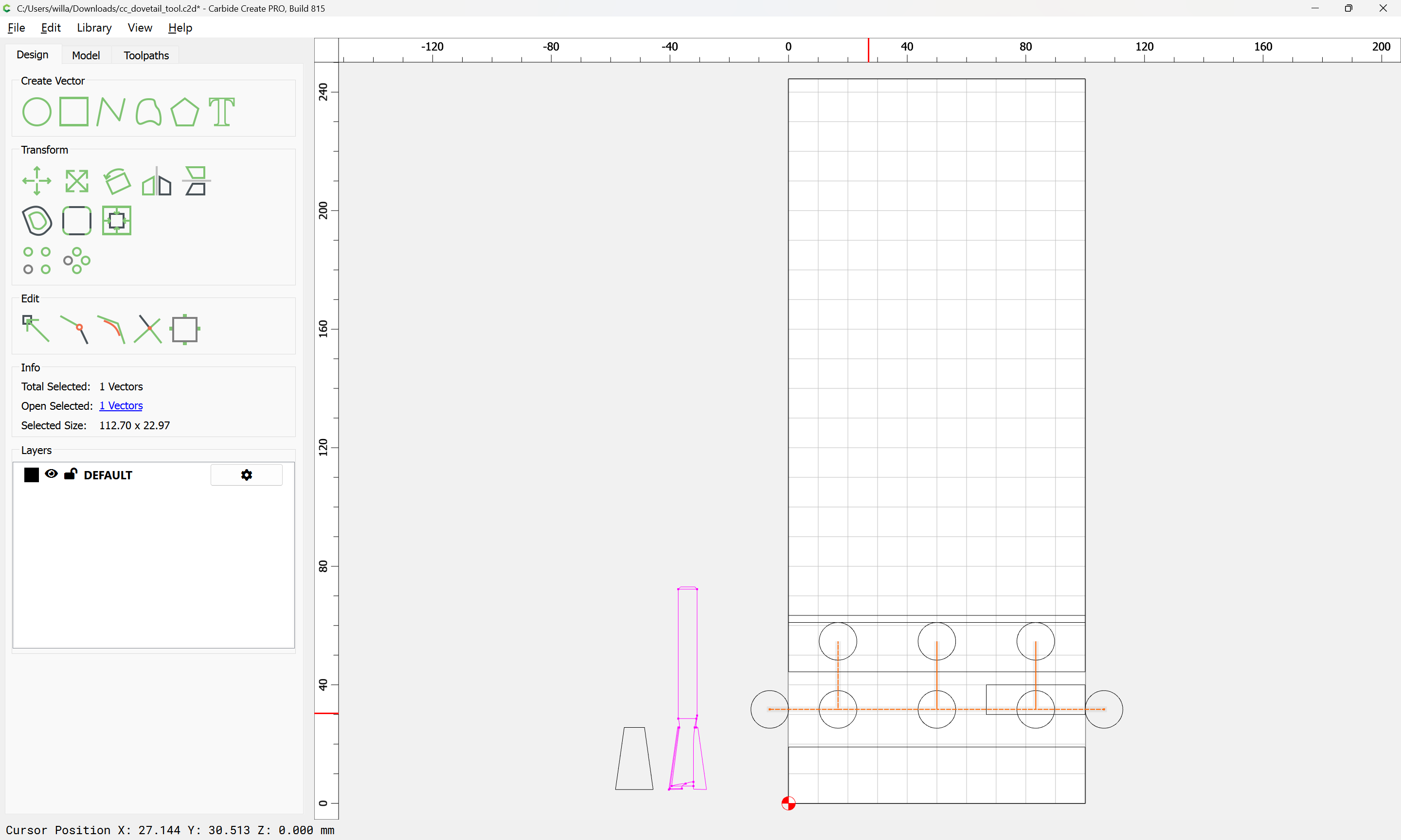
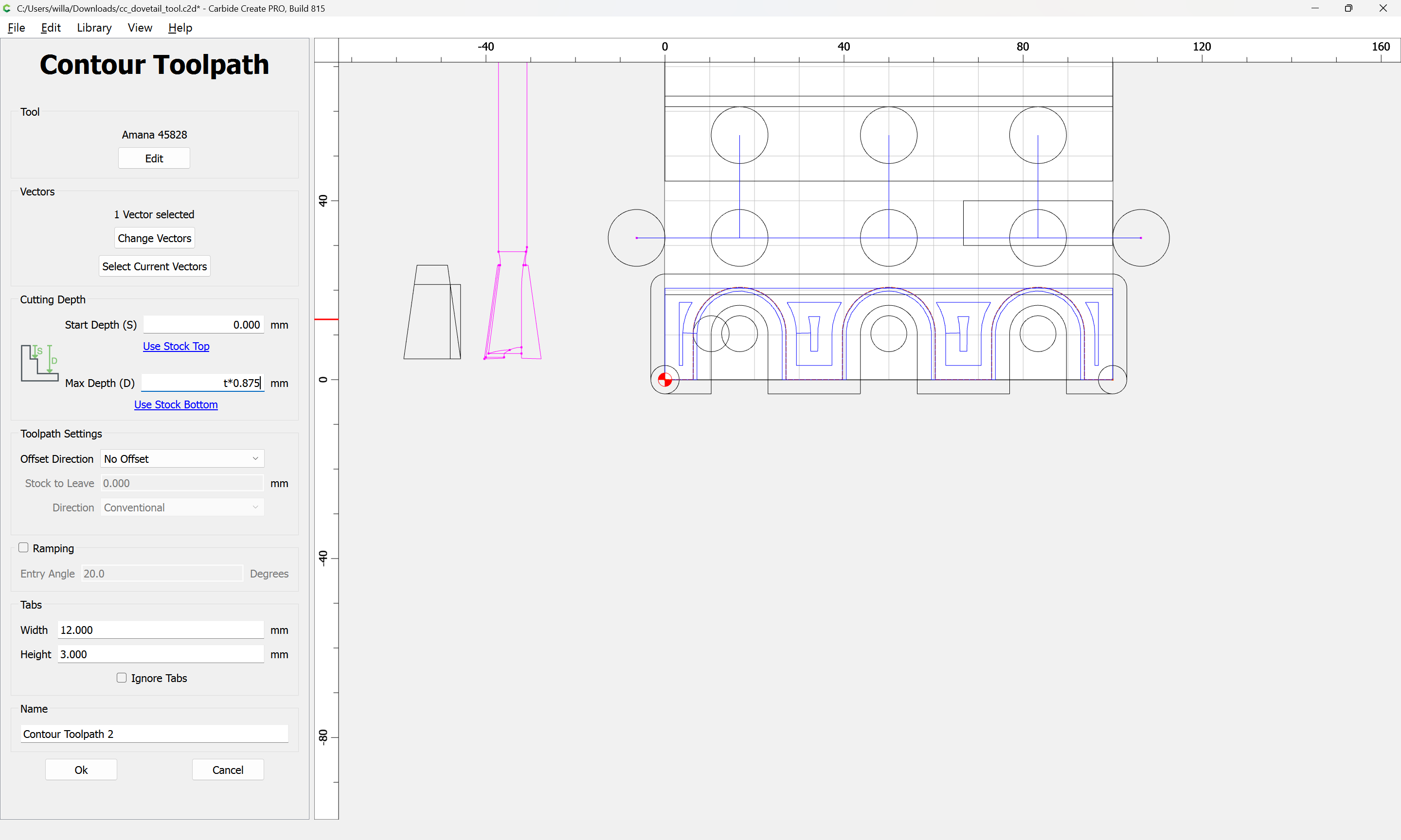
Then assign a No Offset Contour toolpath to the appropriate depth:
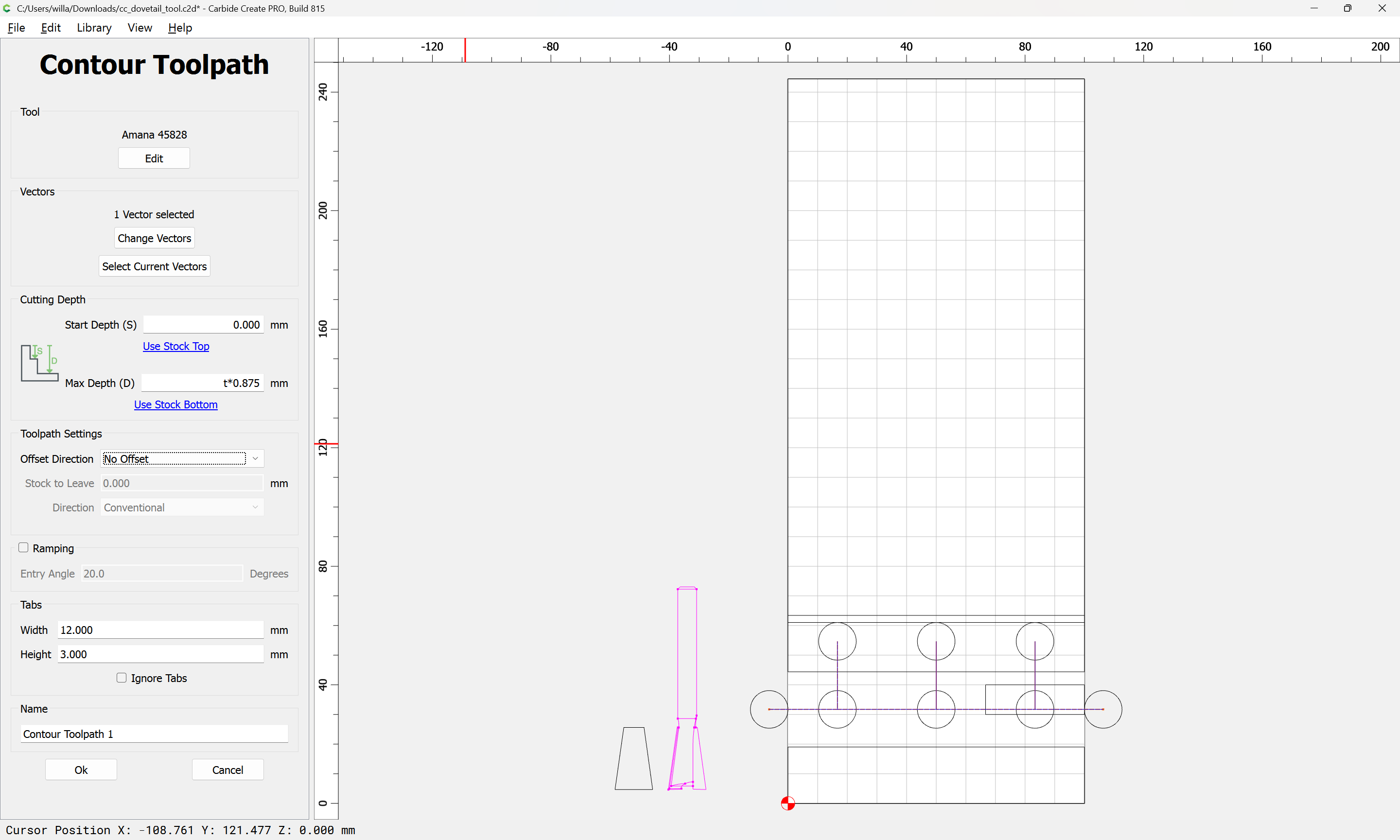
Ensuring that Depth per Pass is greater than Max Depth:
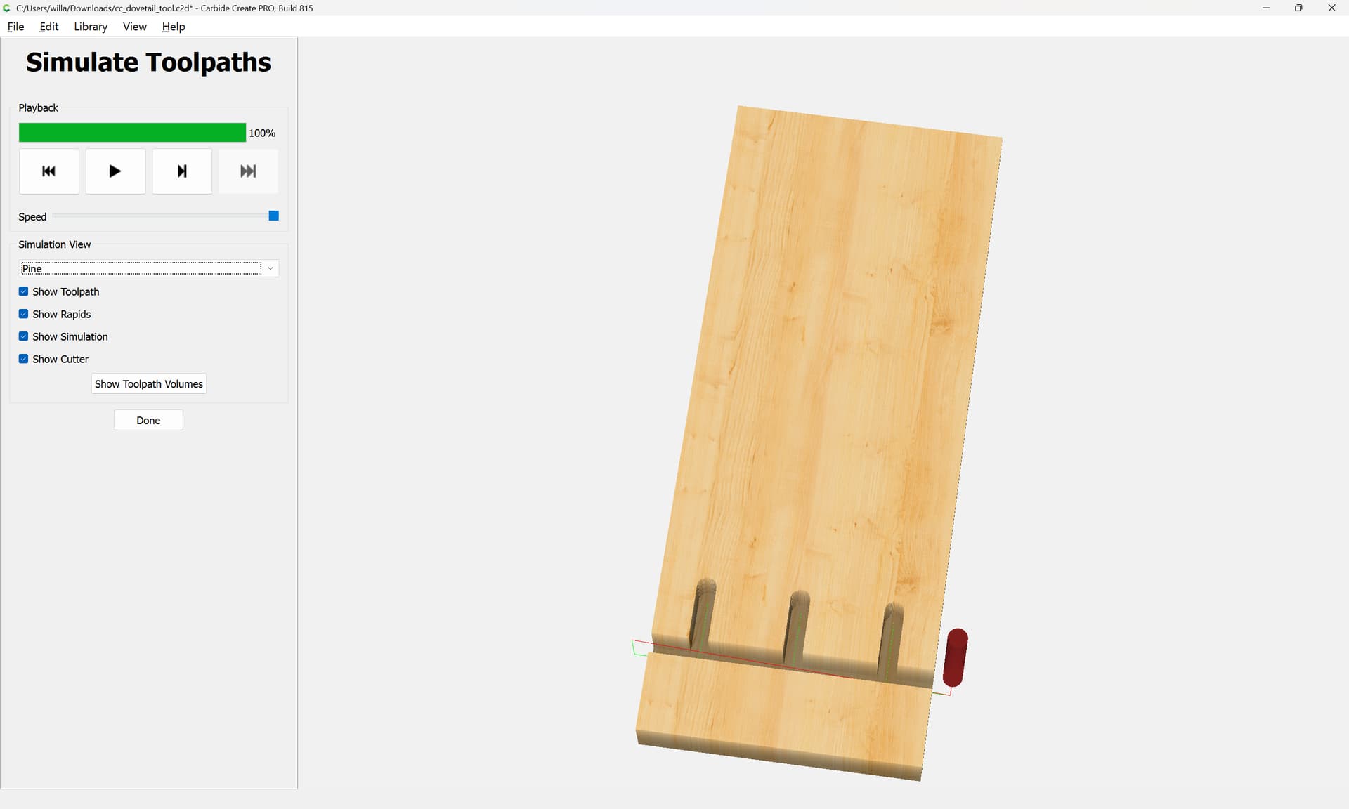
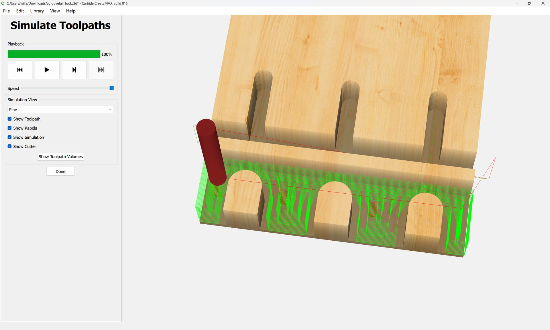
To see how that cut would actually appear, we switch back to BlockSCAD, and do the math to make an equivalent cut.
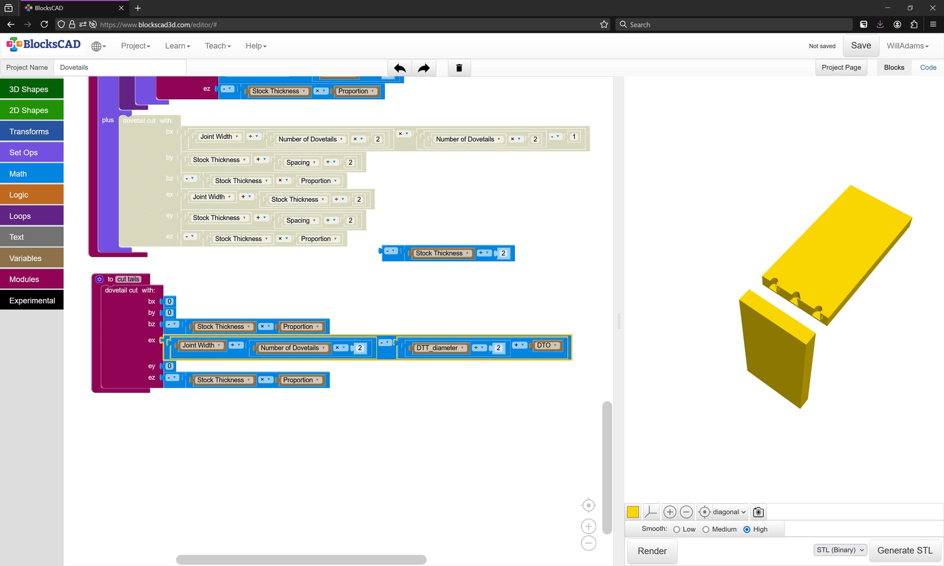
We then define a module to make a cut with the Dovetail tool:
and use it in defining a module to cut the pins — the beginning and end are quite obvious:
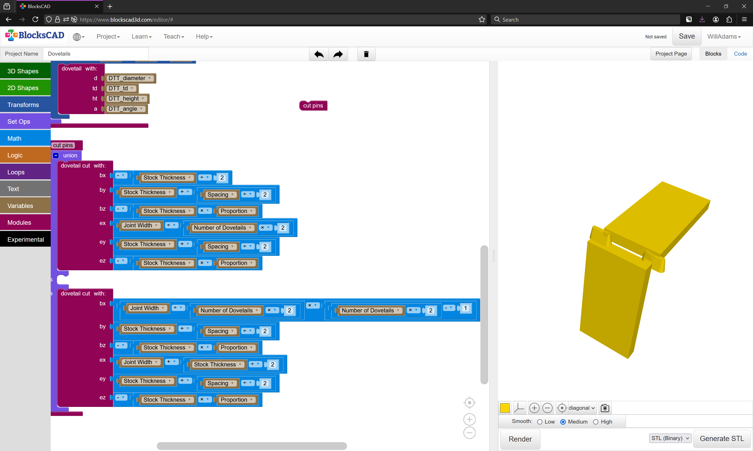
The middle requires a loop…
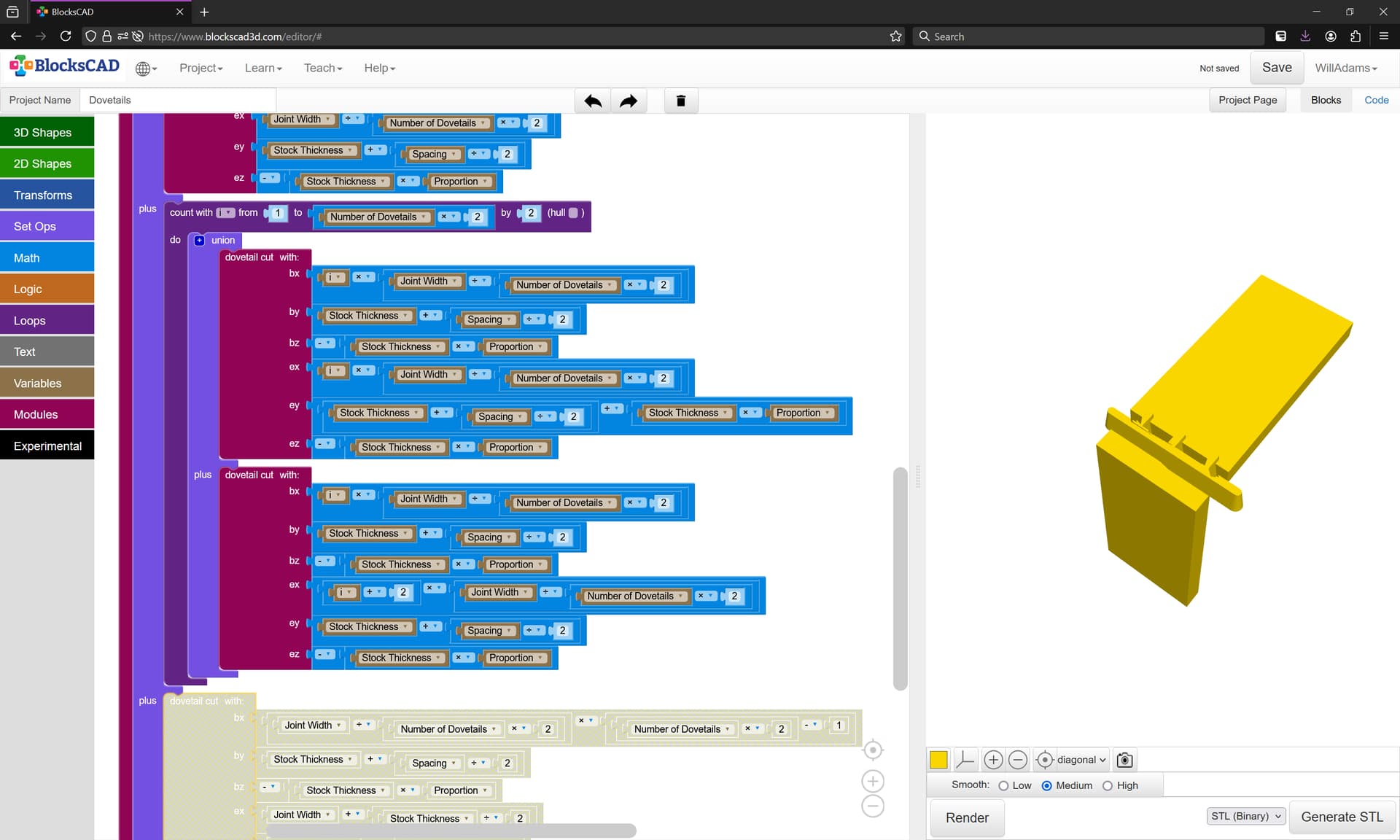
(and if we allow a bit of over-cutting, the previous last bit can be disabled)
Subtracting that from the stock we get:
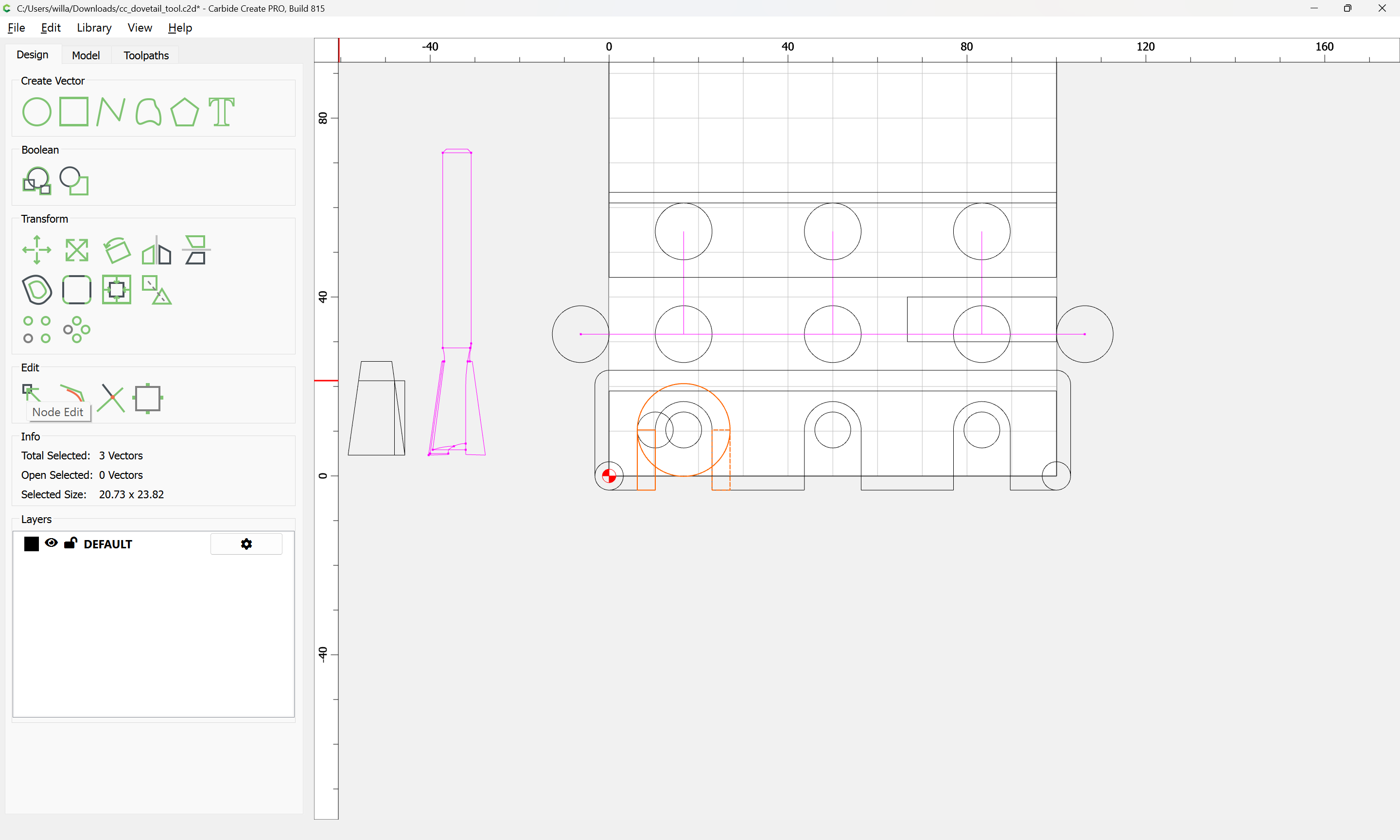
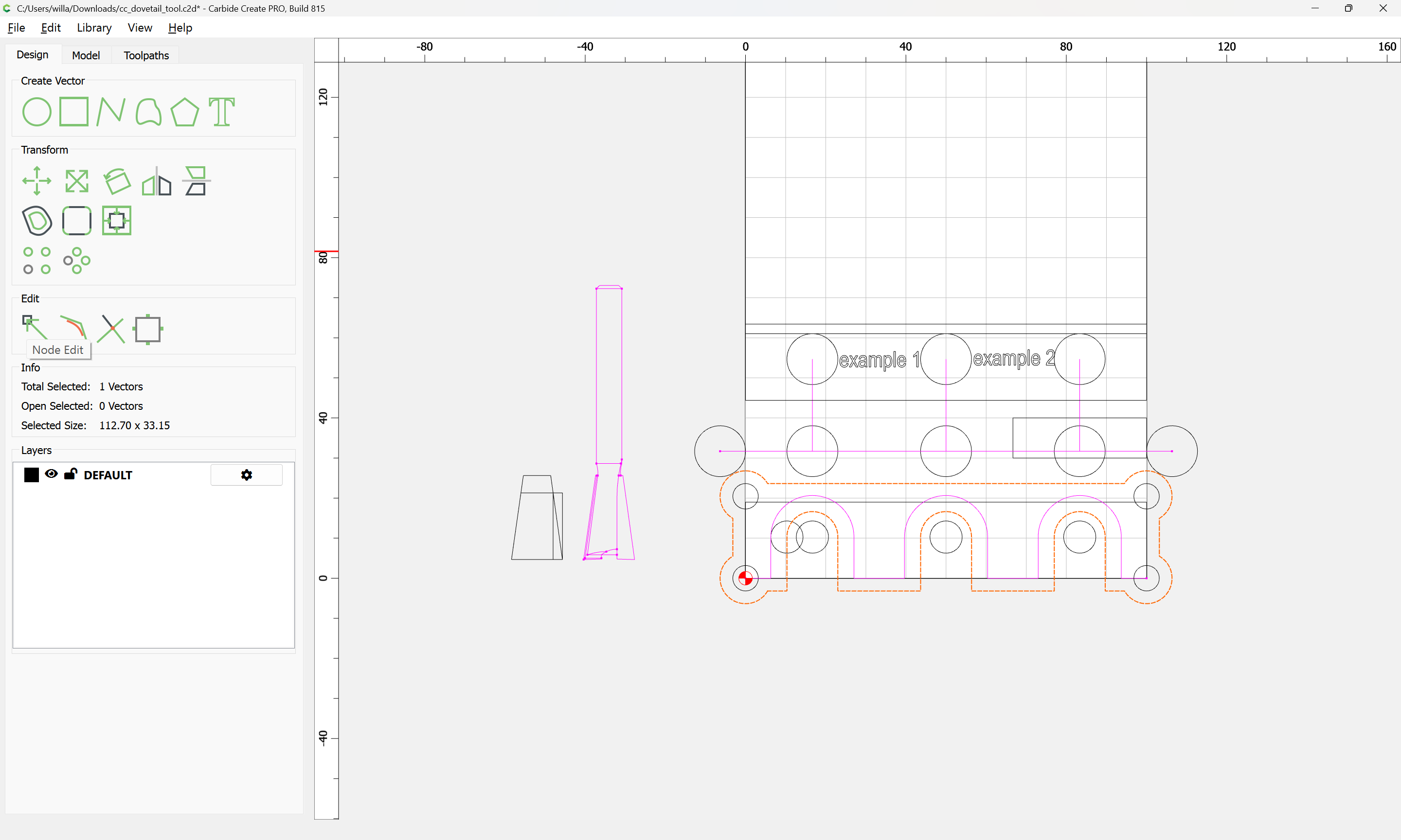
which leaves cutting the tails, which requires some arcs — first, we draw this up in Carbide Create…
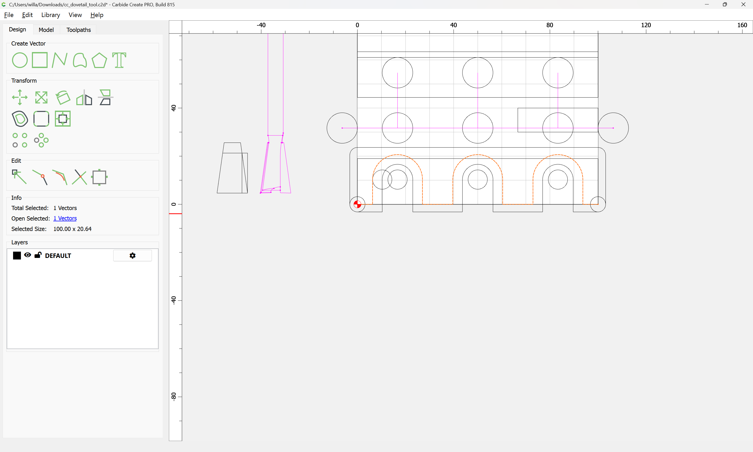
Cutting the tails is a matter of removing the material around the material cut away for the pins, so we duplicate that geometry:
and draw in geometry to make clear what needs to be kept and what cut away. Note that it will be necessary to ensure that a tool can pass fully around the geometry:

arriving at:
OK
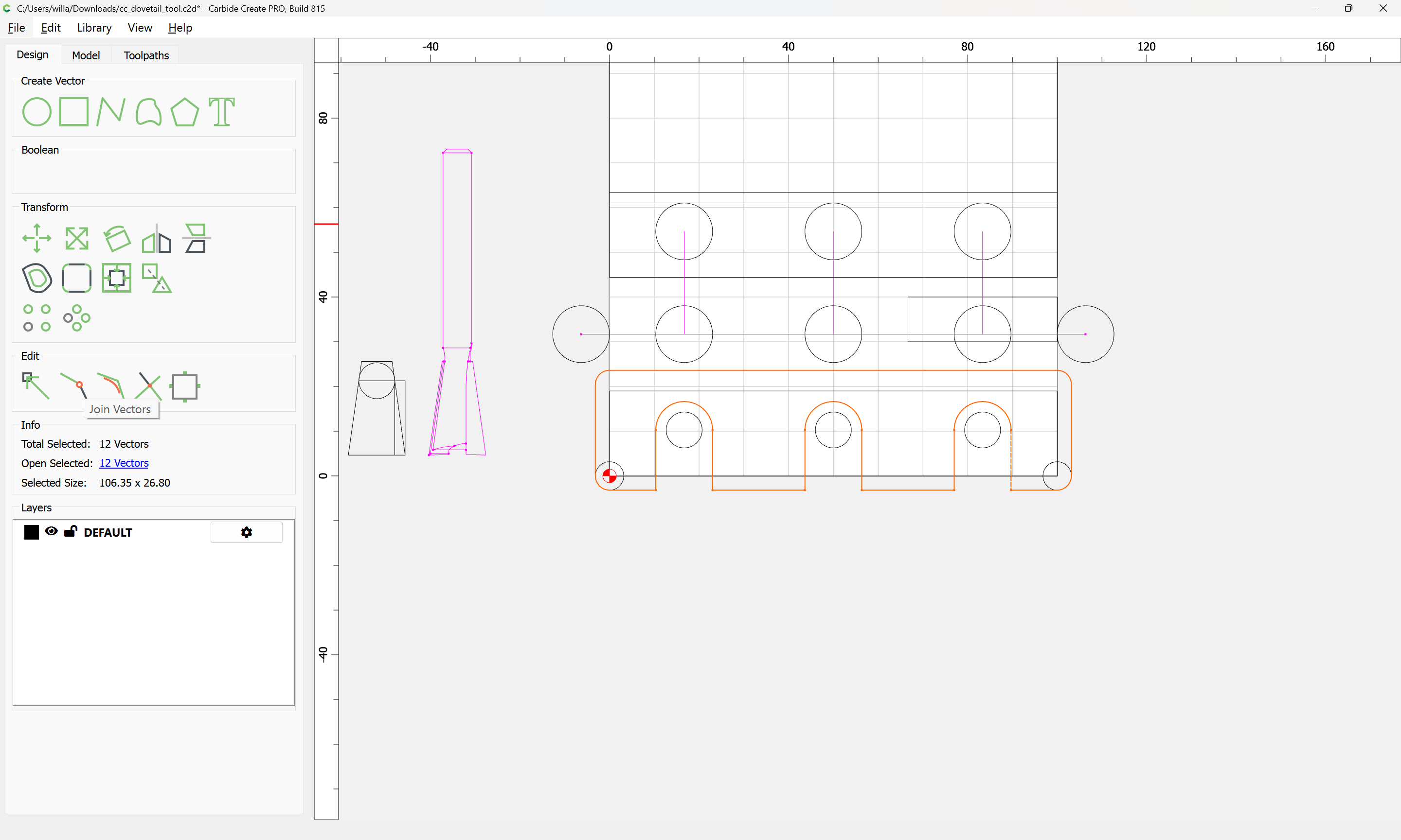
Join Vectors
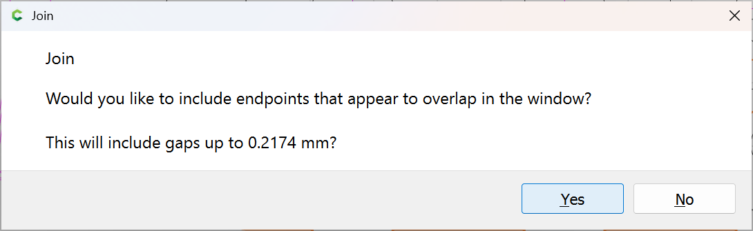
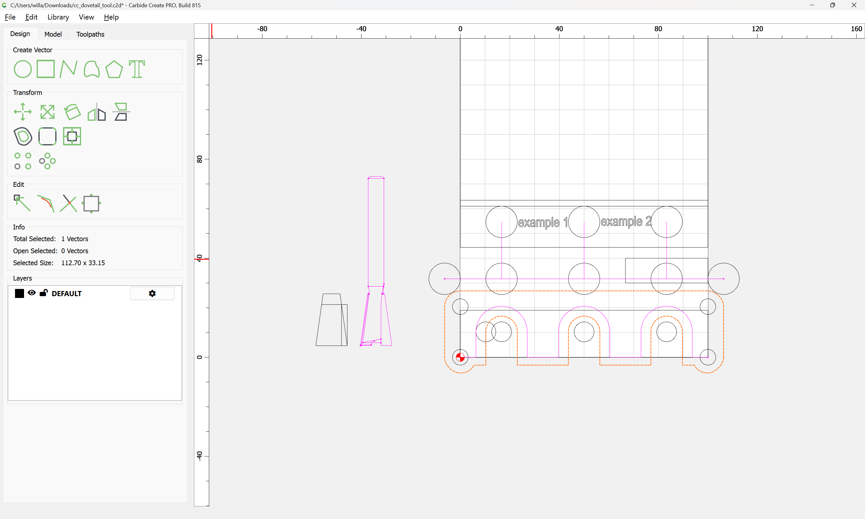
Yes
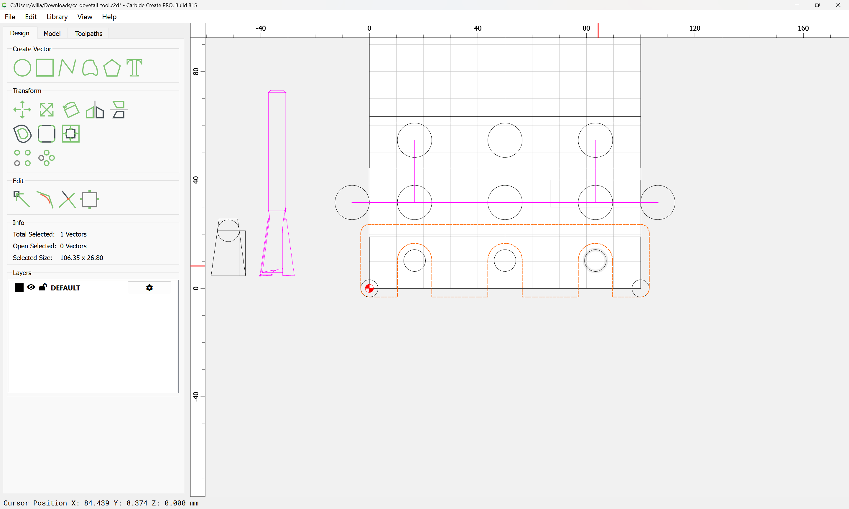
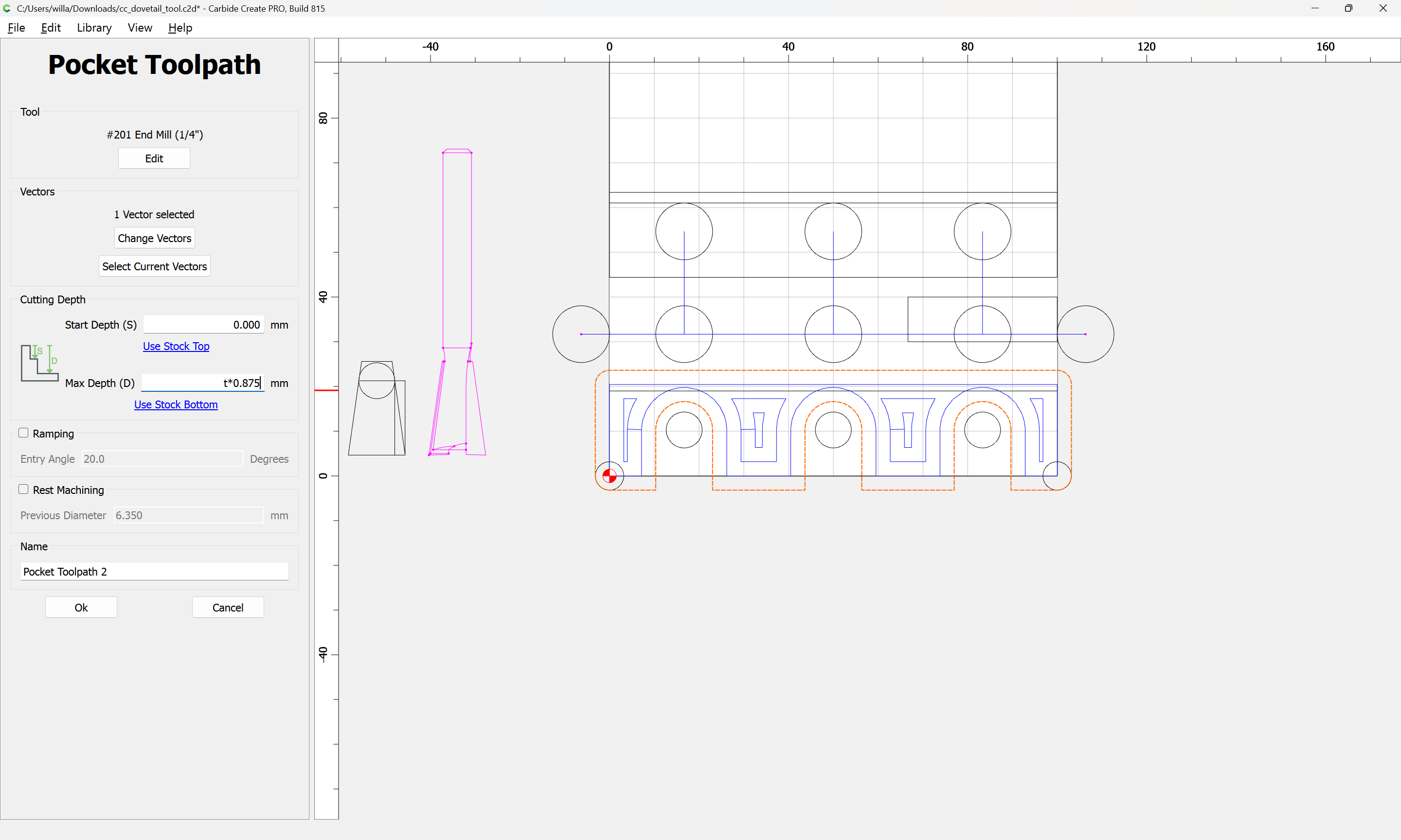
which may then be assigned a Pocket Toolpath:
Then we need to draw in the geometry for the Dovetail tool to finish cutting the tails.
Using the circle which describes the diameter of the top of the cut:
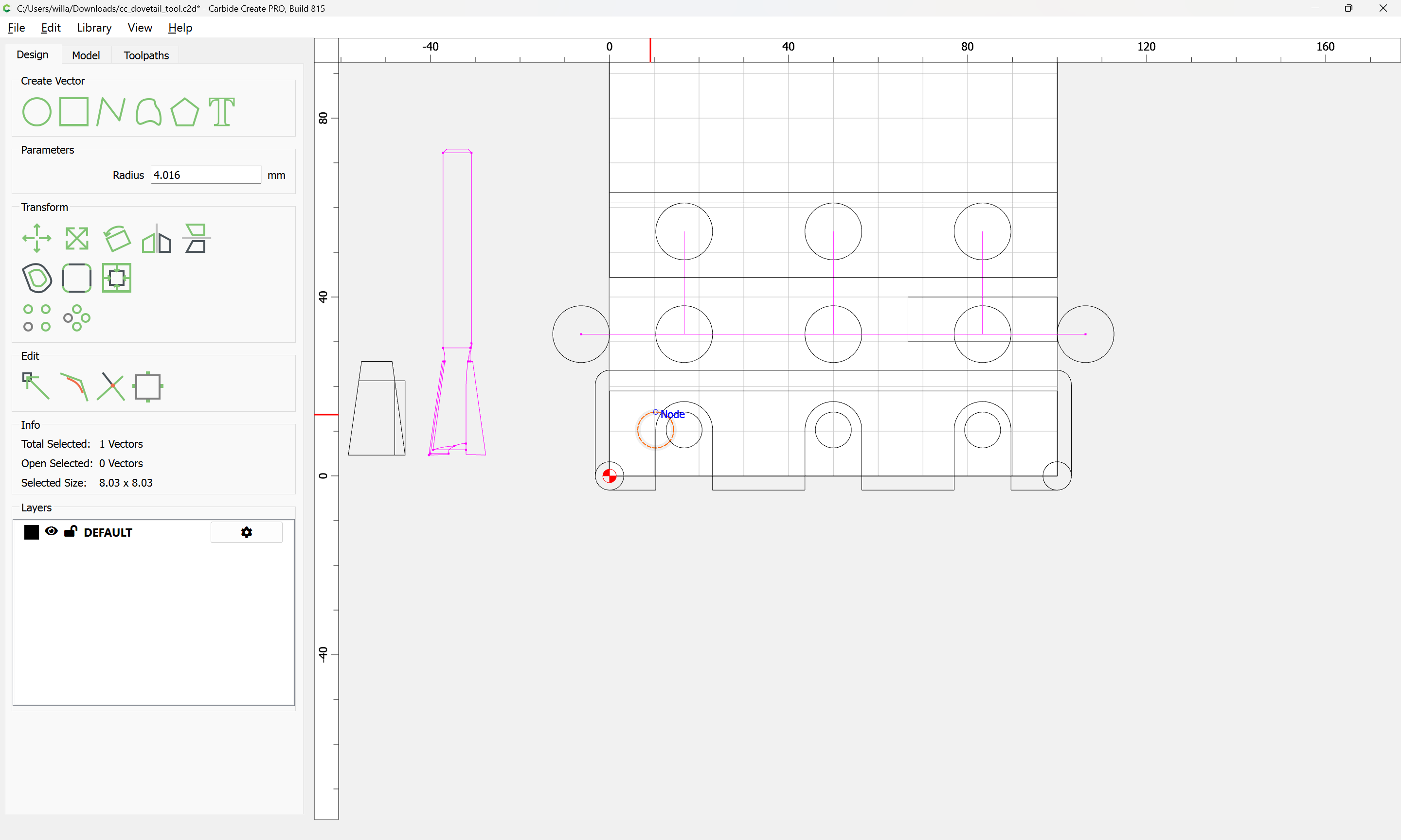
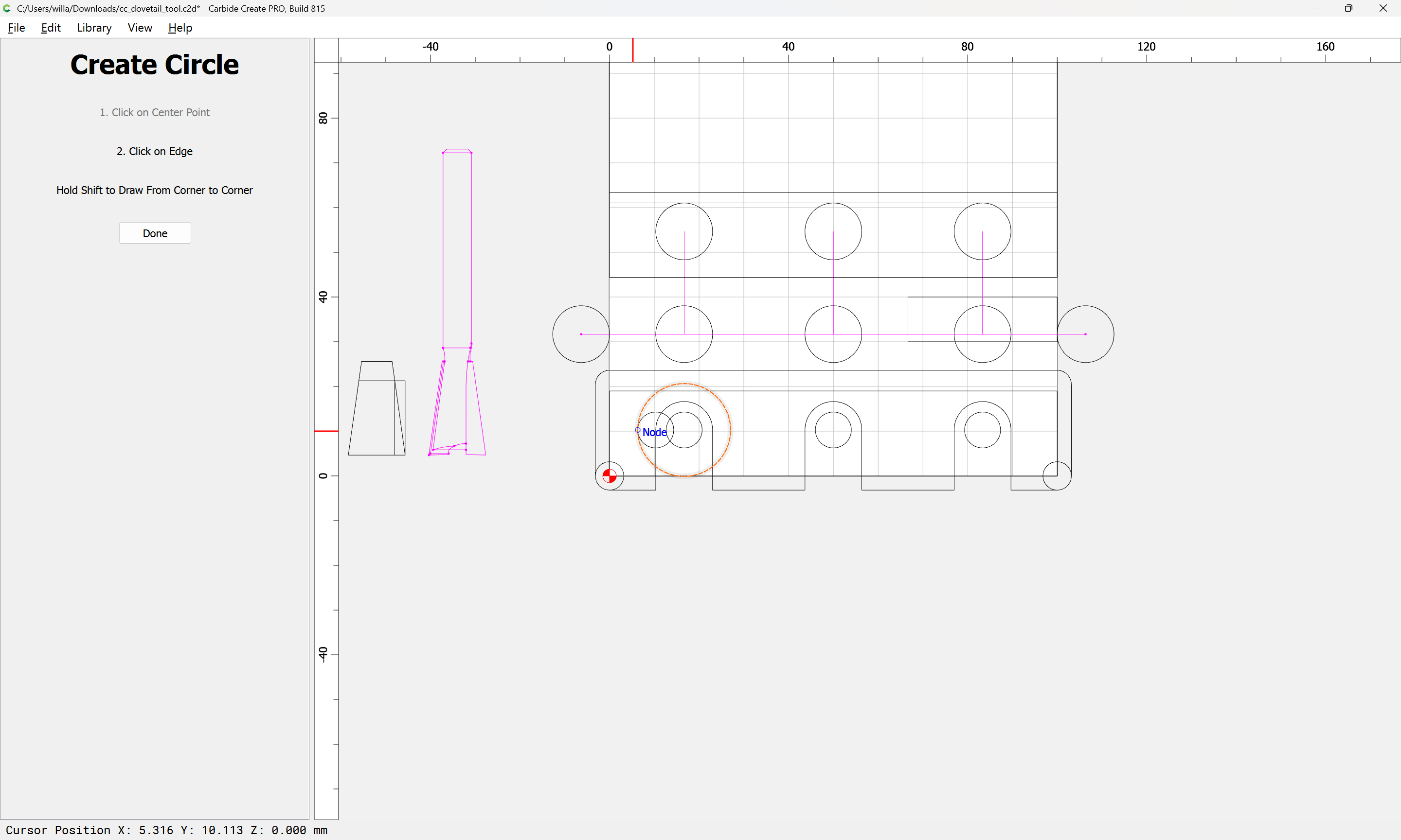

Done
Join Vectors
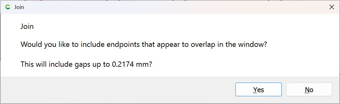
Yes
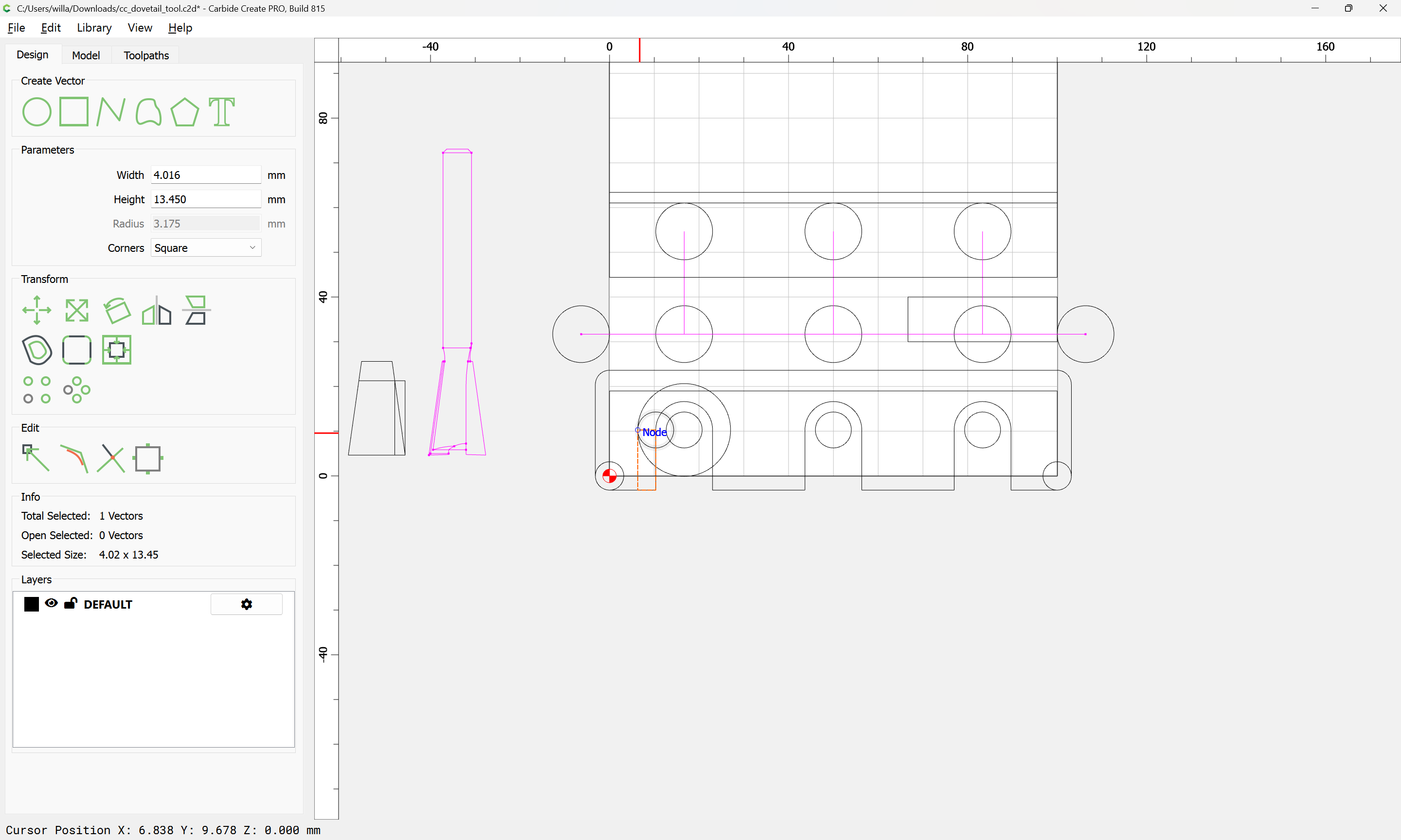
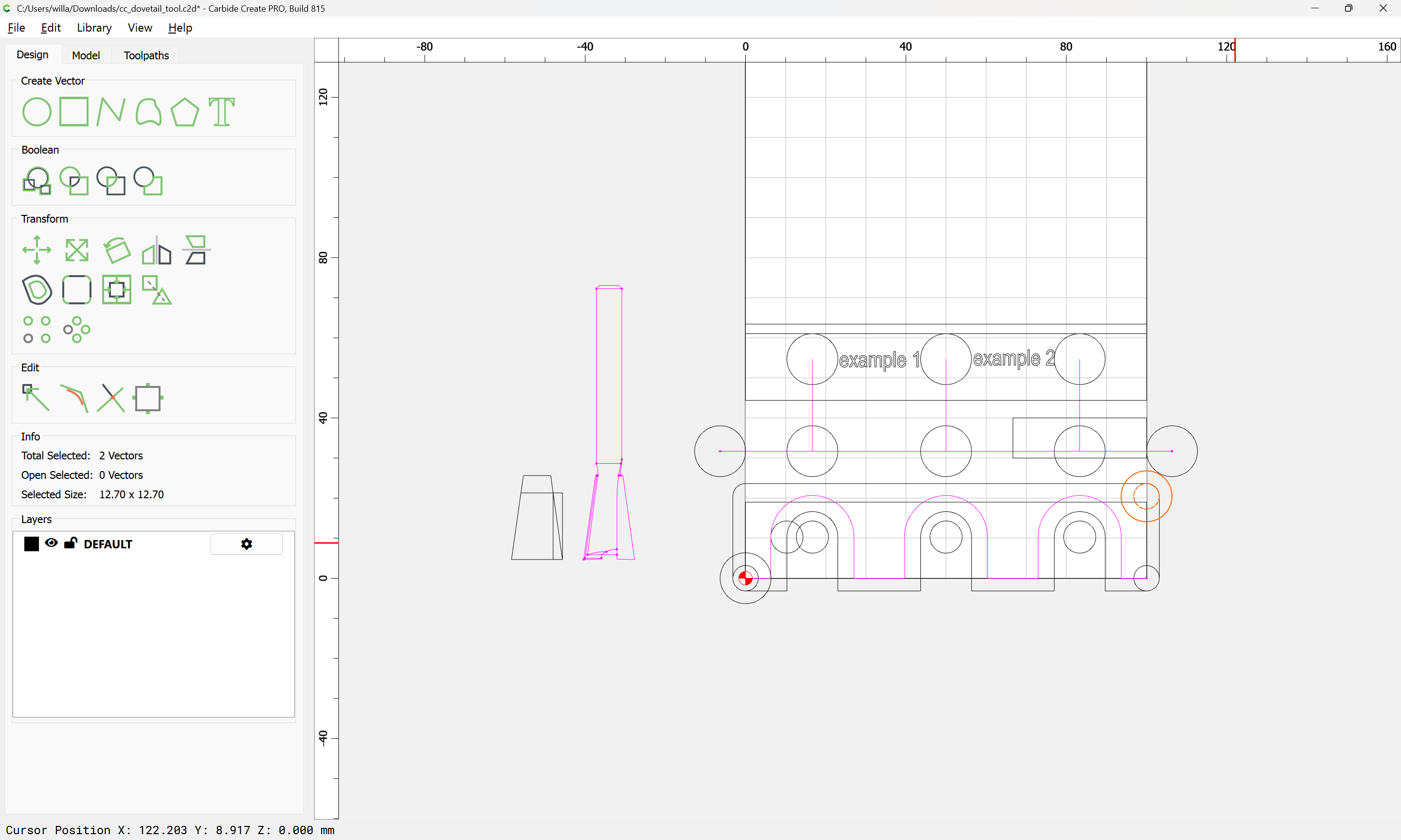
select a circle to use for positioning:
copy-paste:
and drag into position:
repeating:
Draw a line for the base cut:
Done
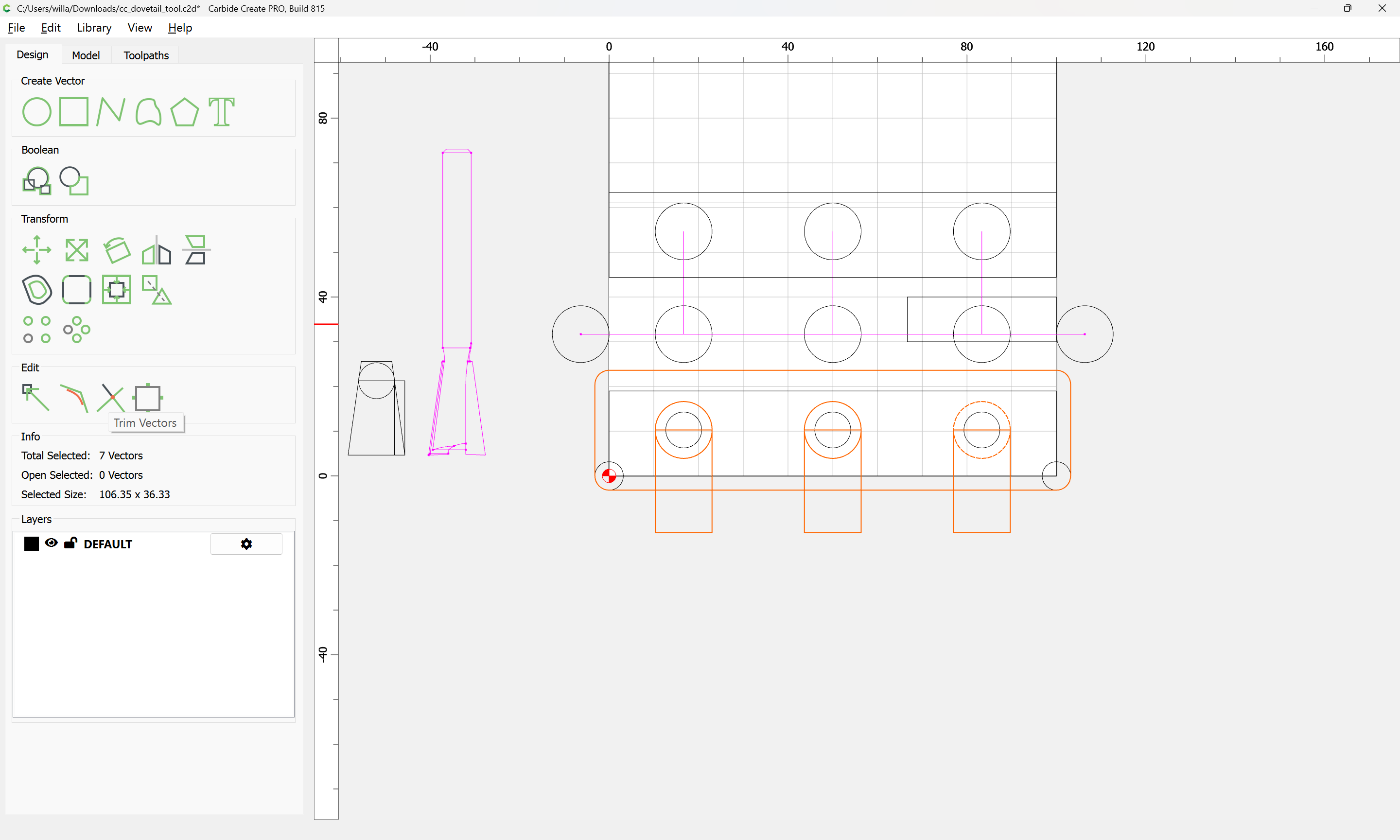
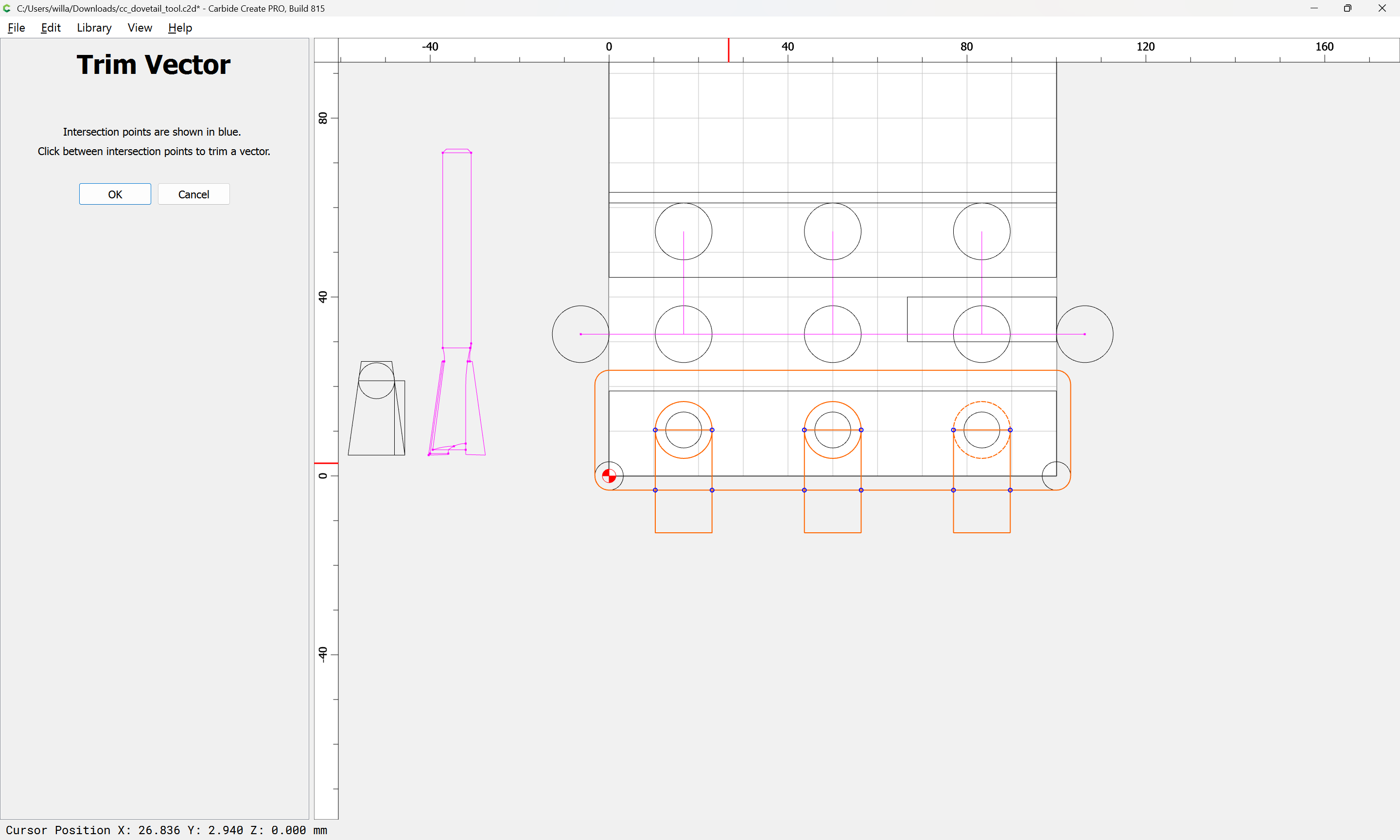
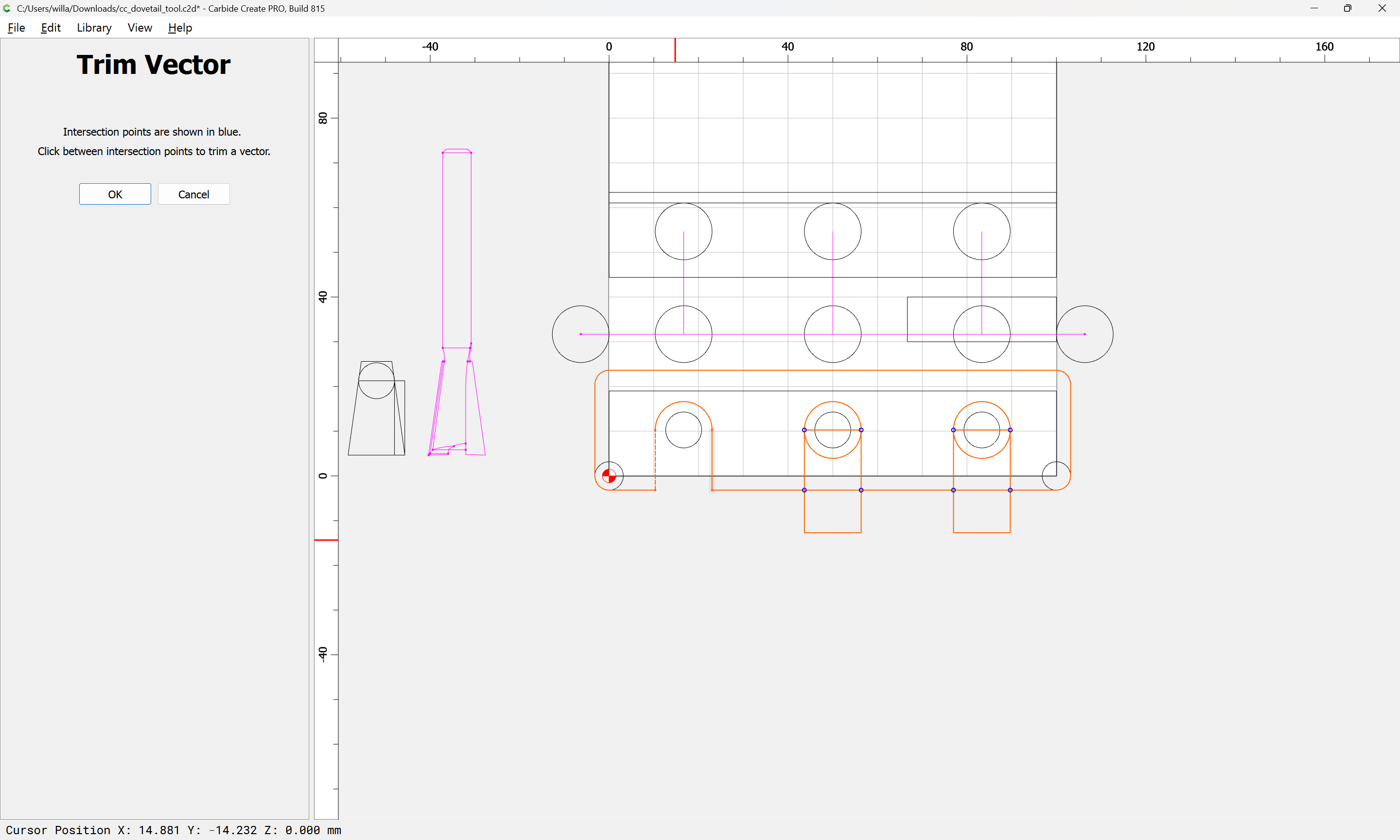
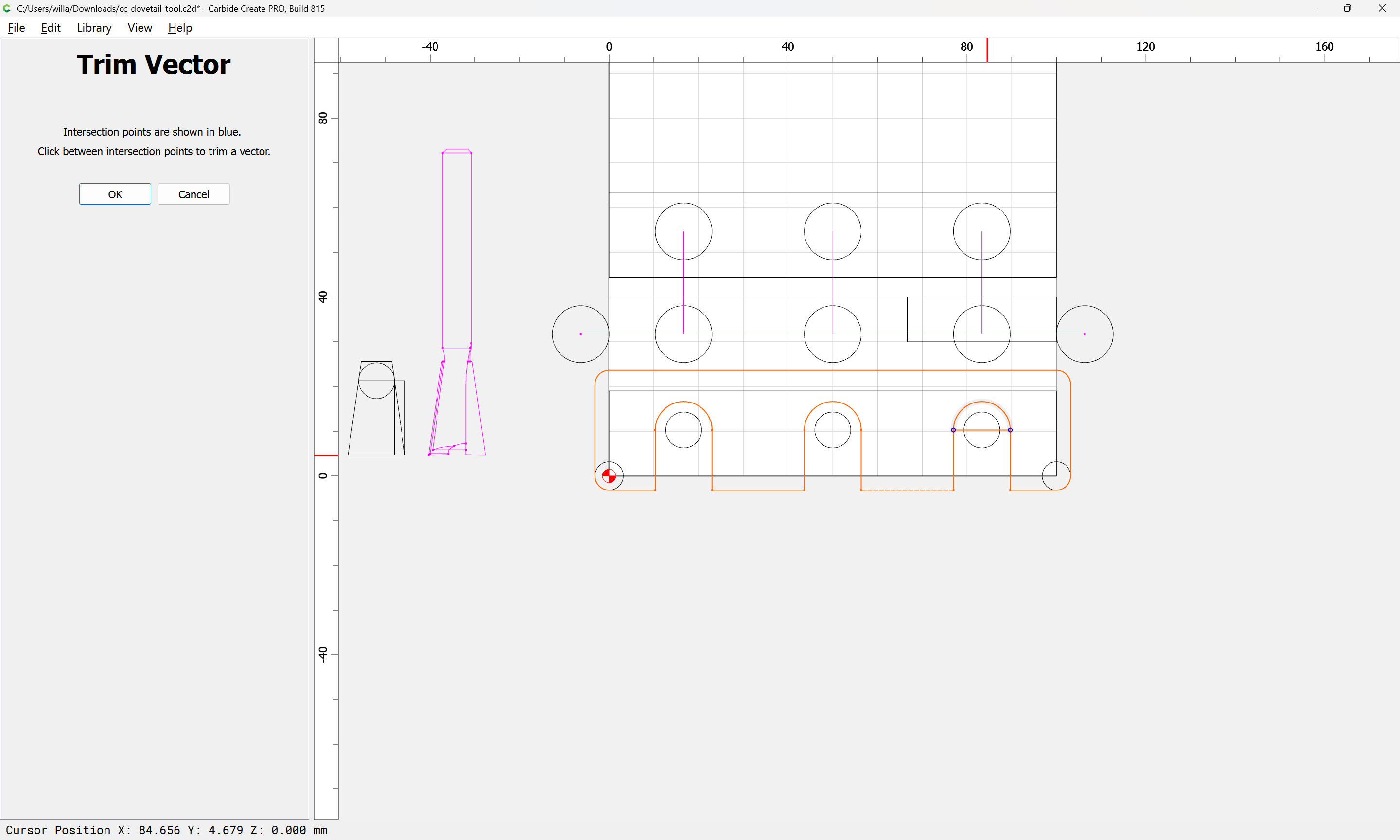
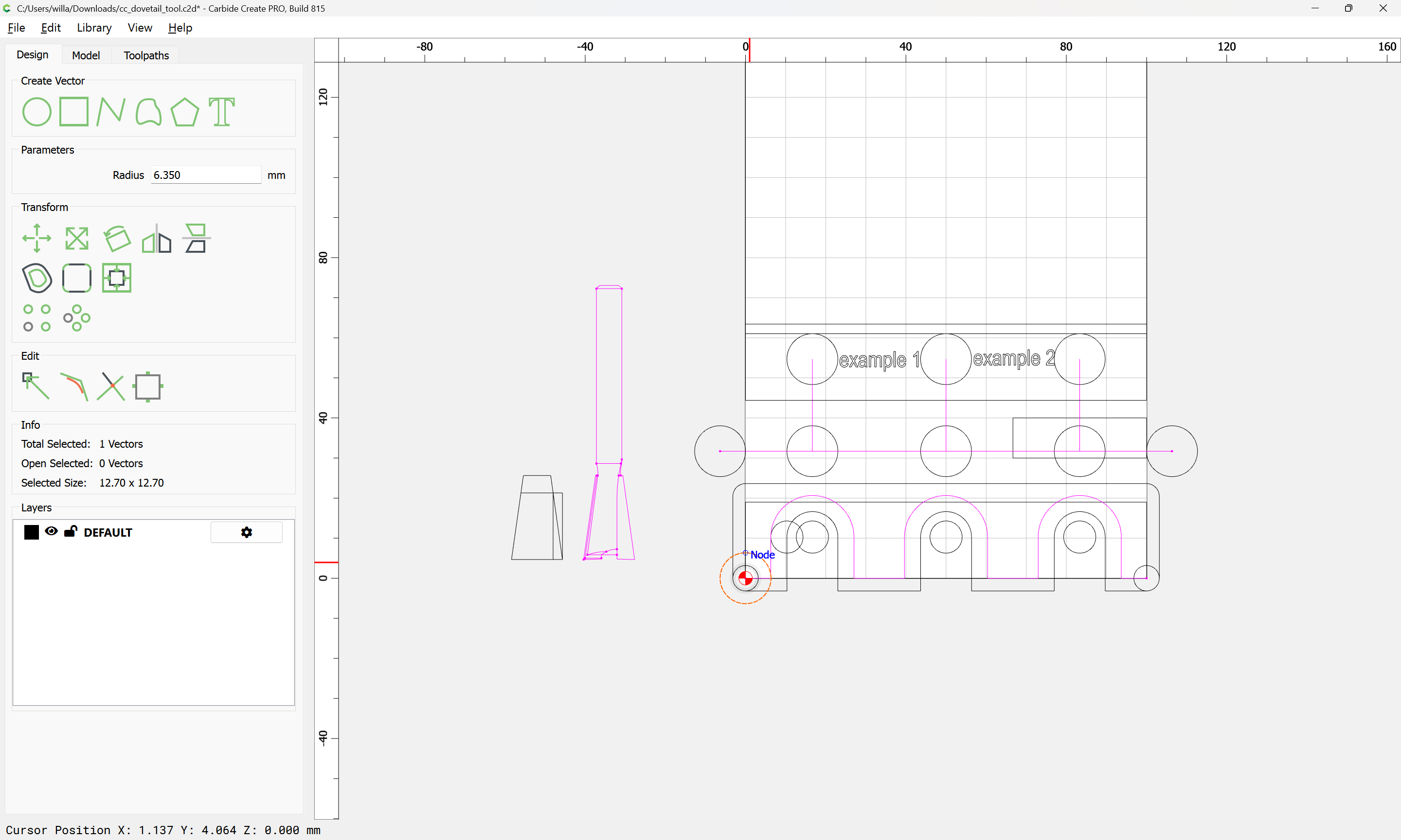
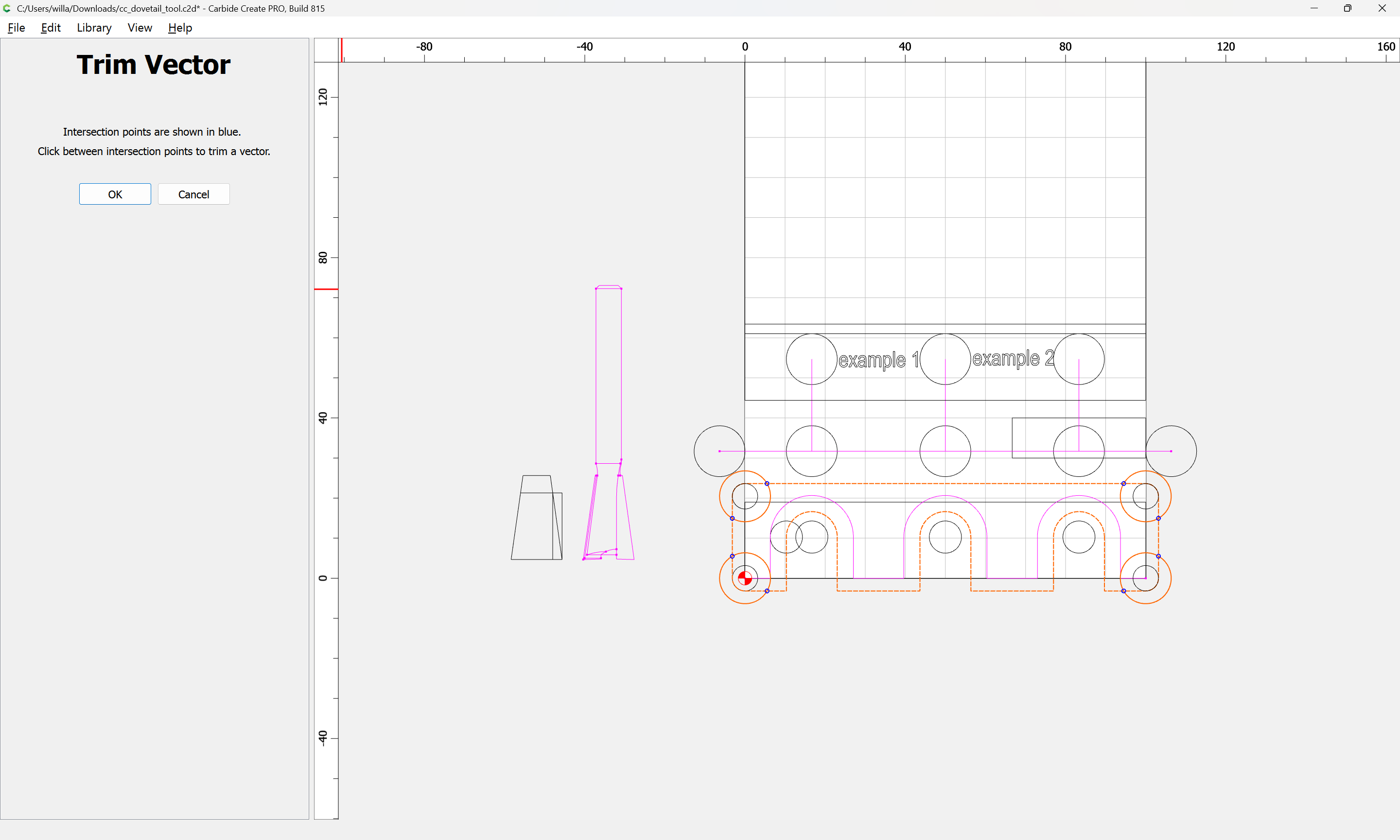
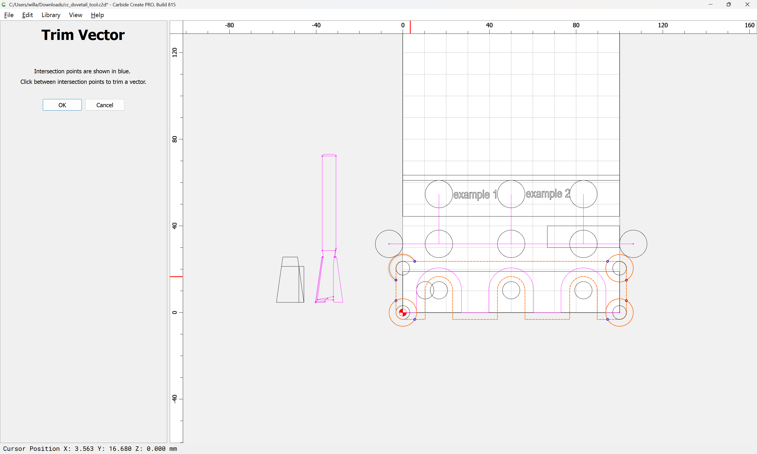
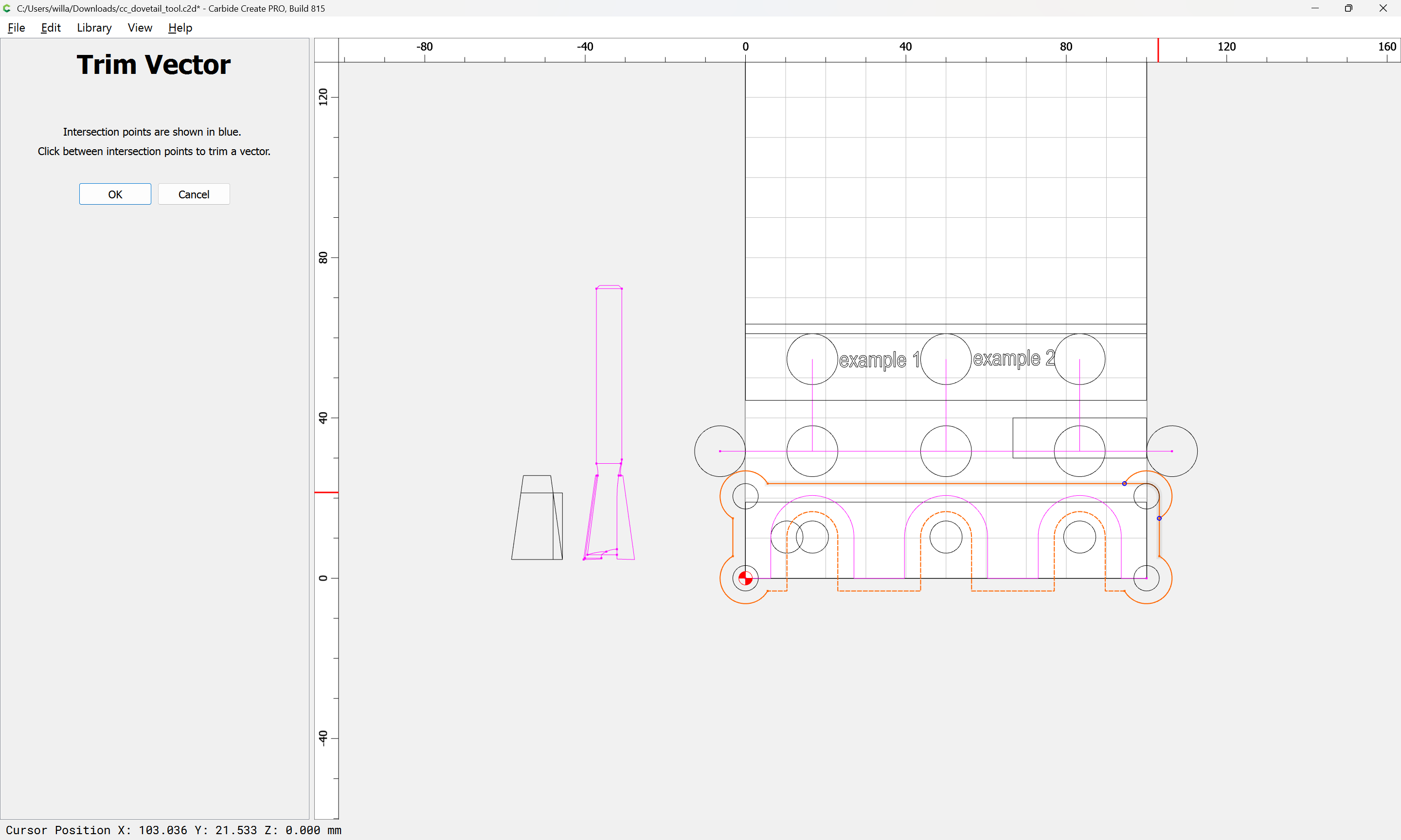
Select the geometry for the toolpath:
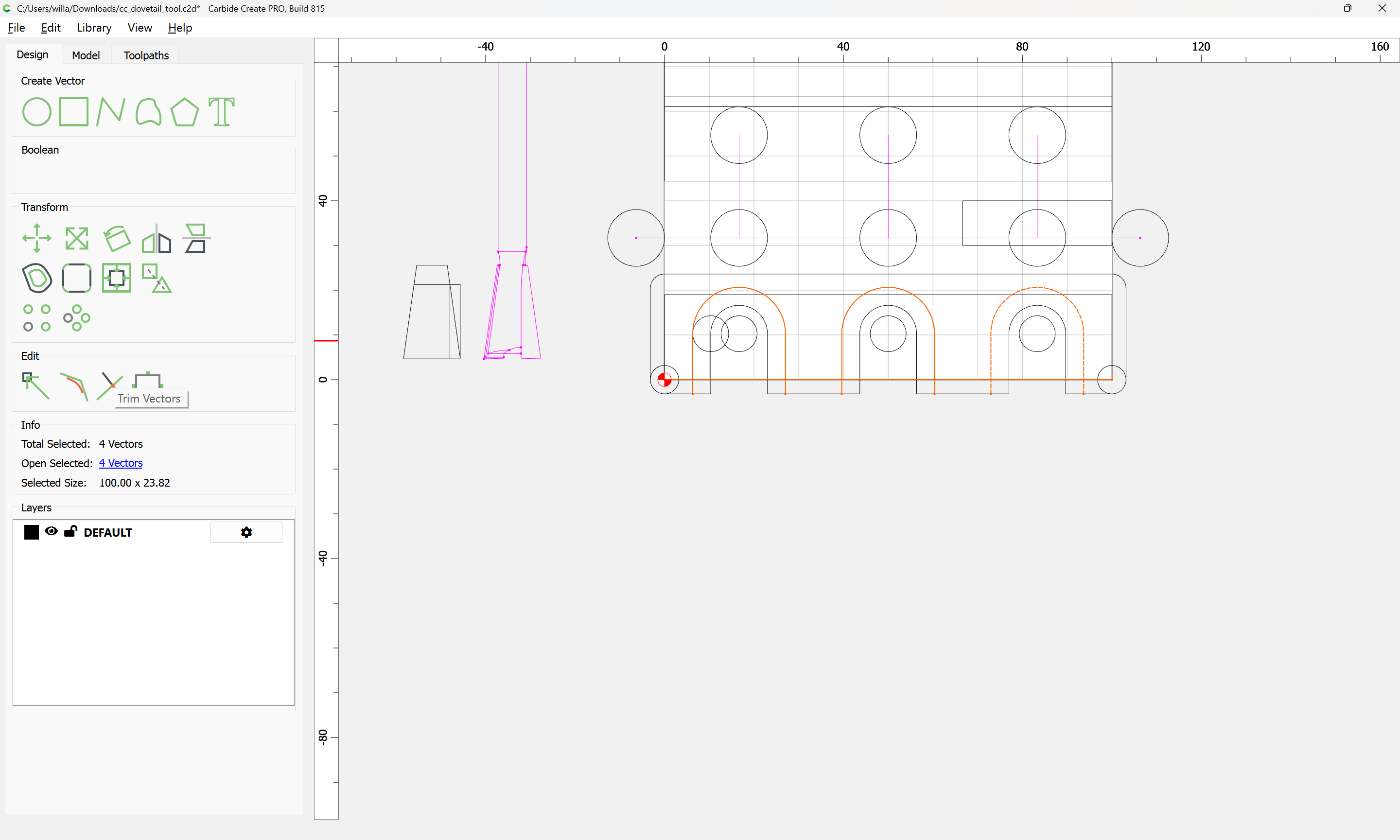
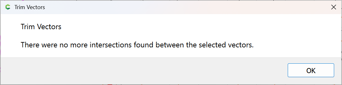
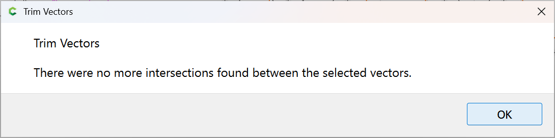
and use Trim Vectors to remove what is not wanted:
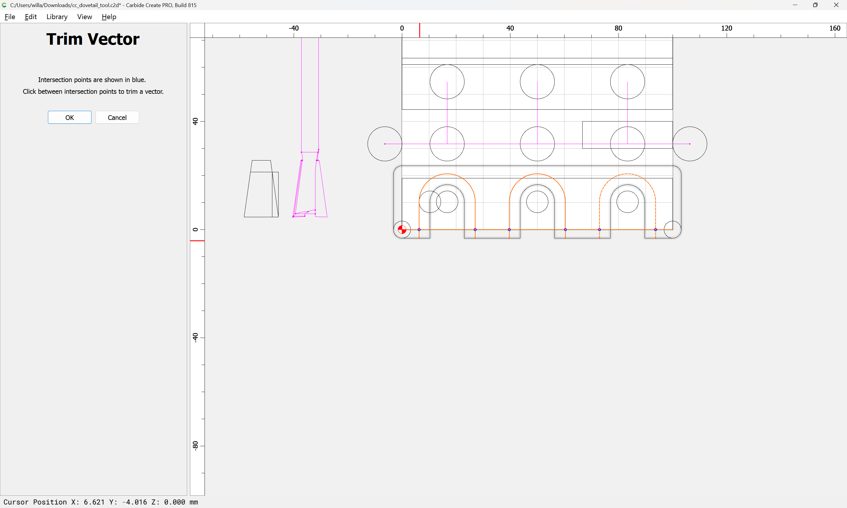
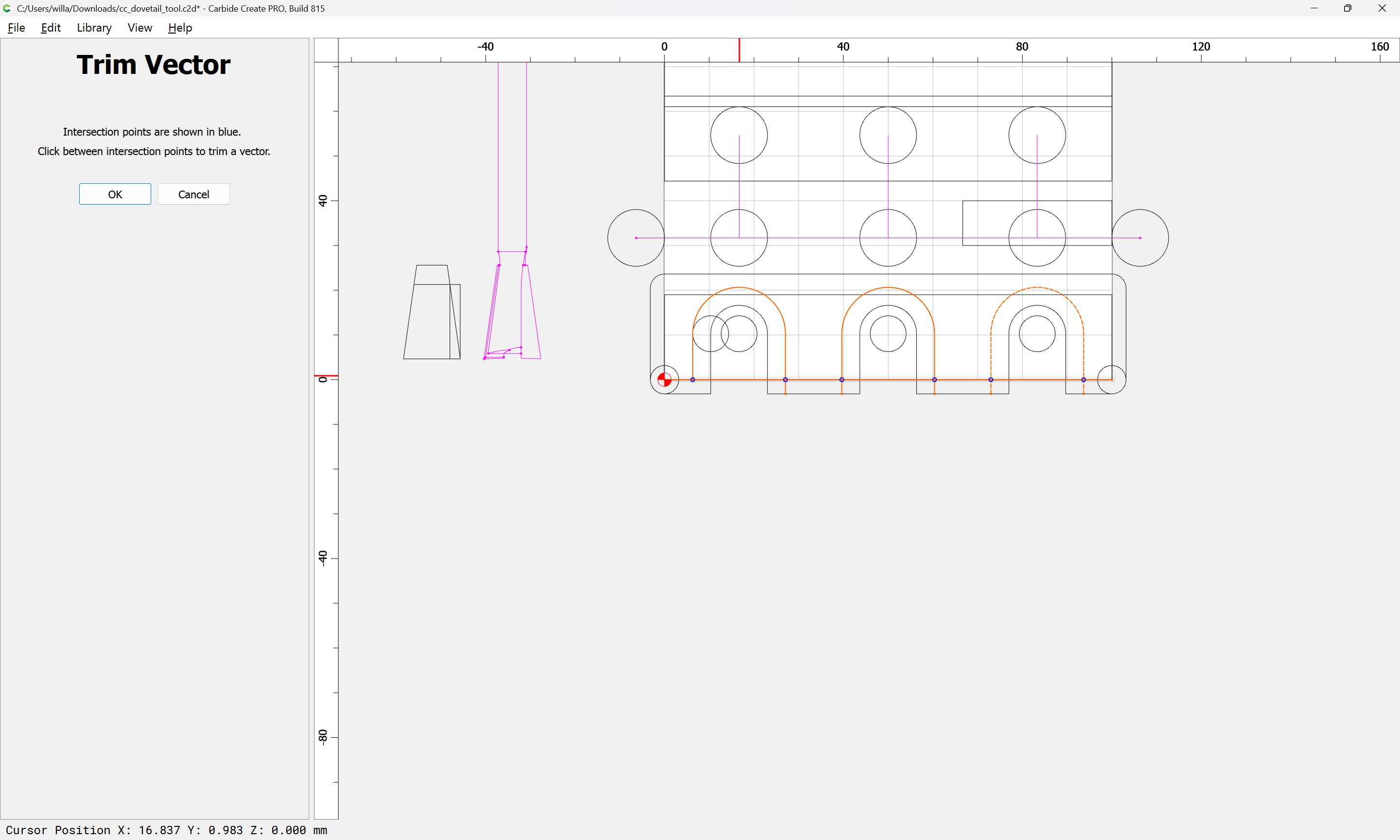
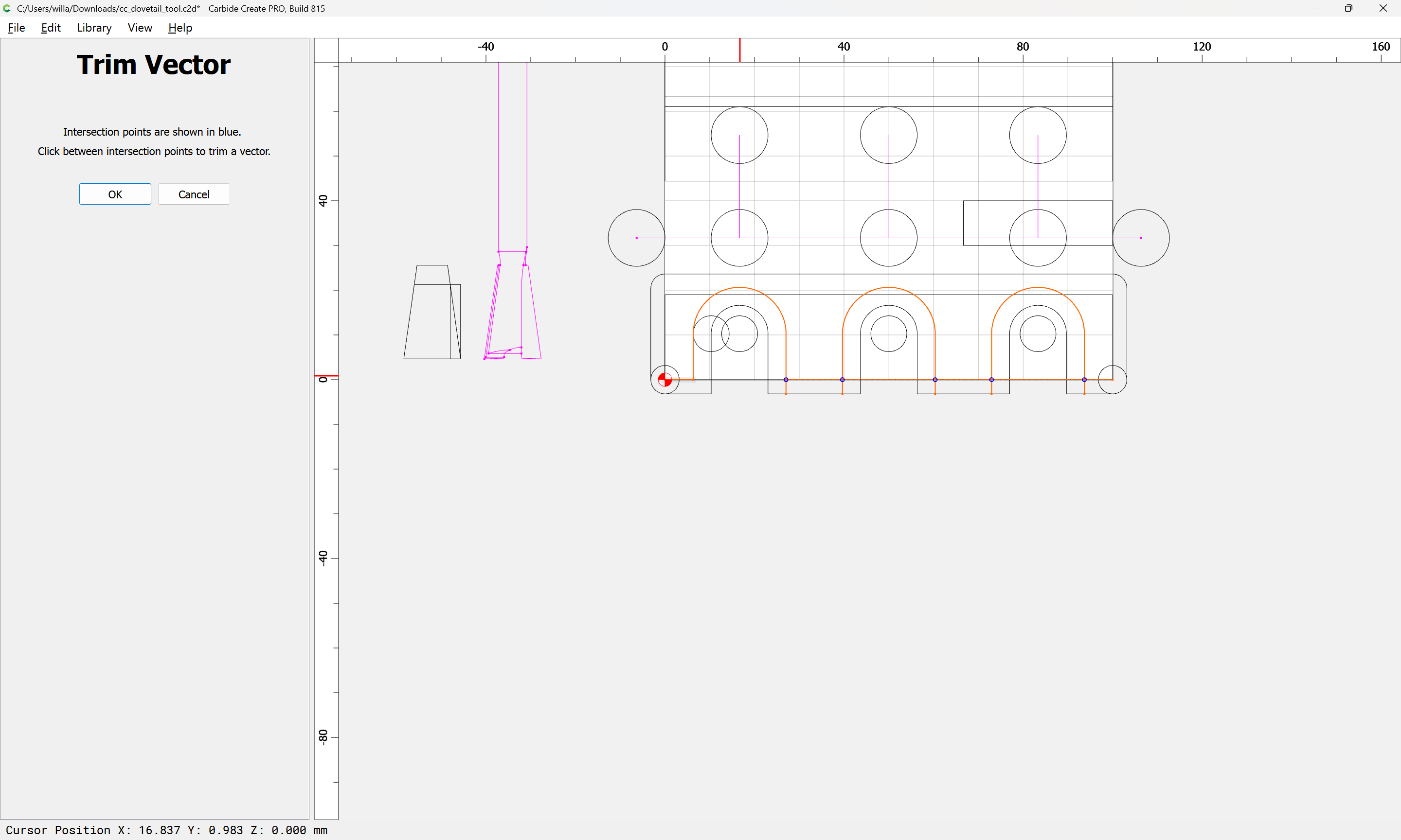
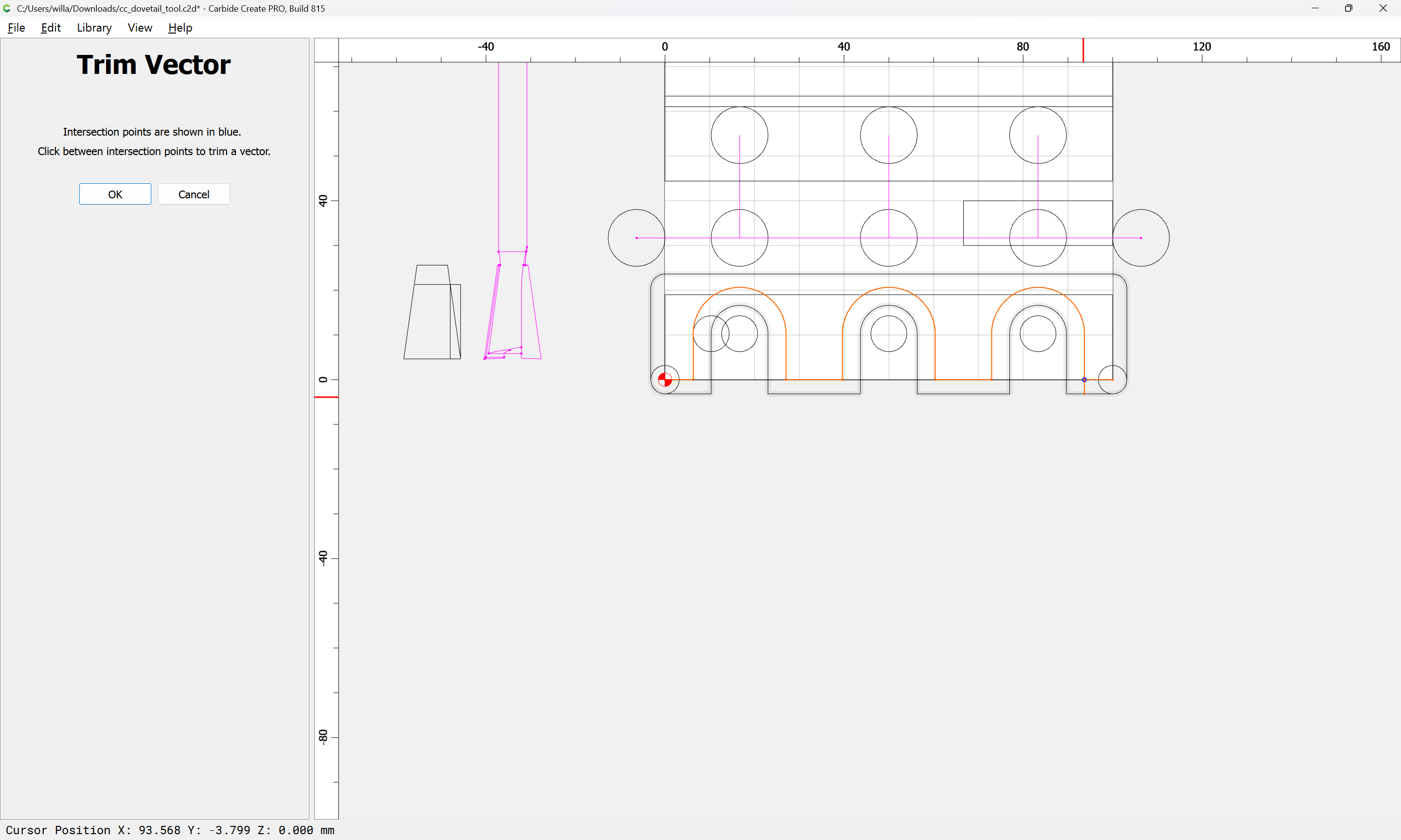
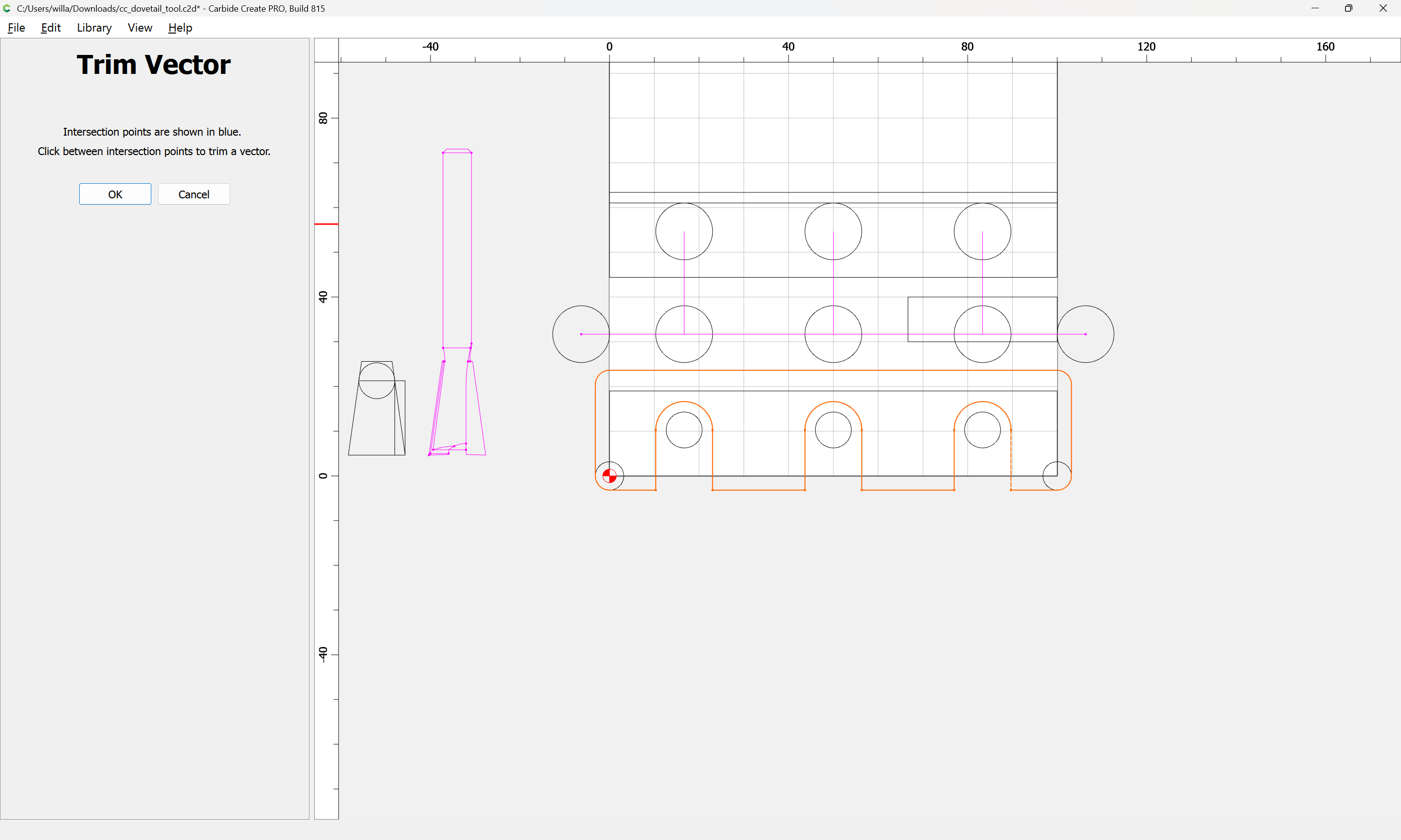
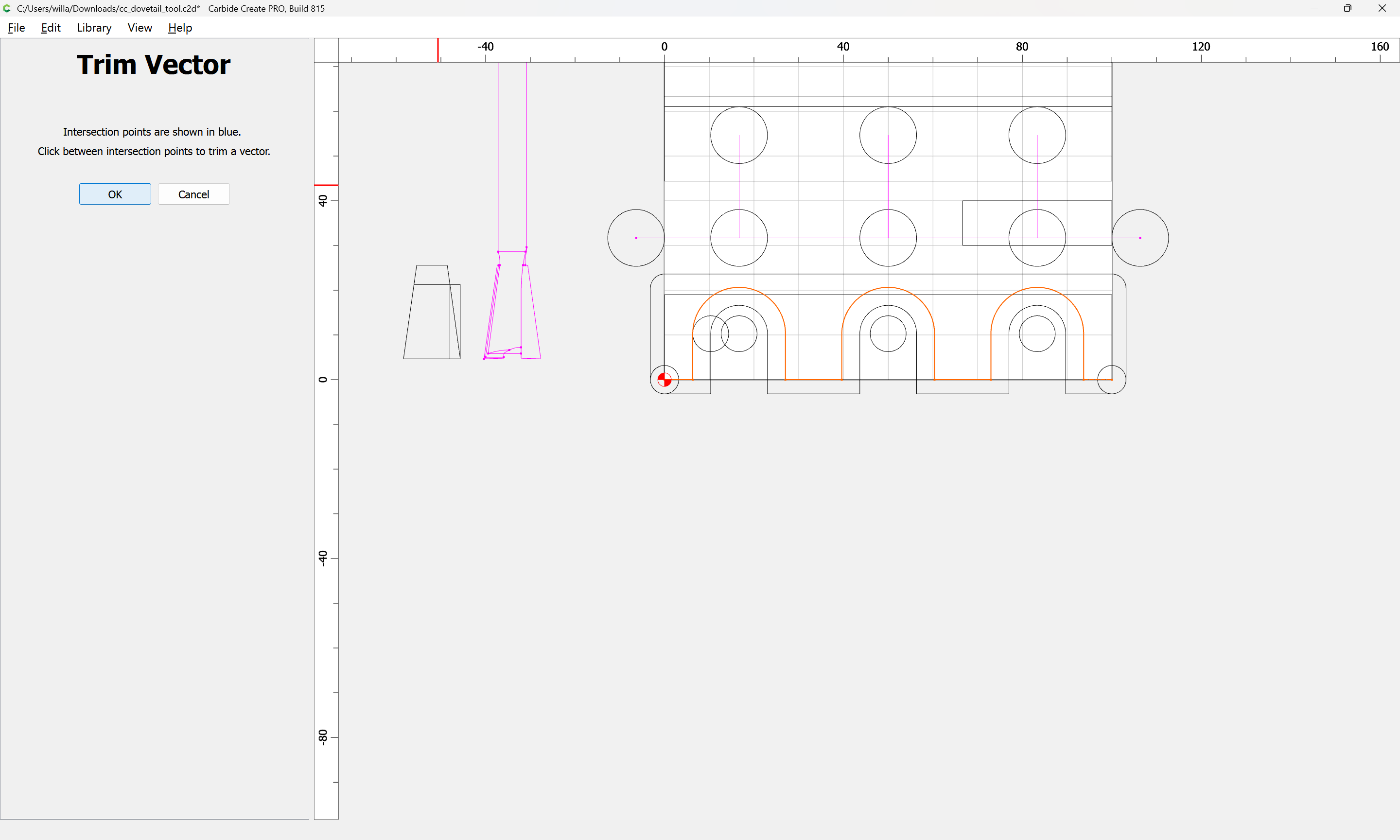
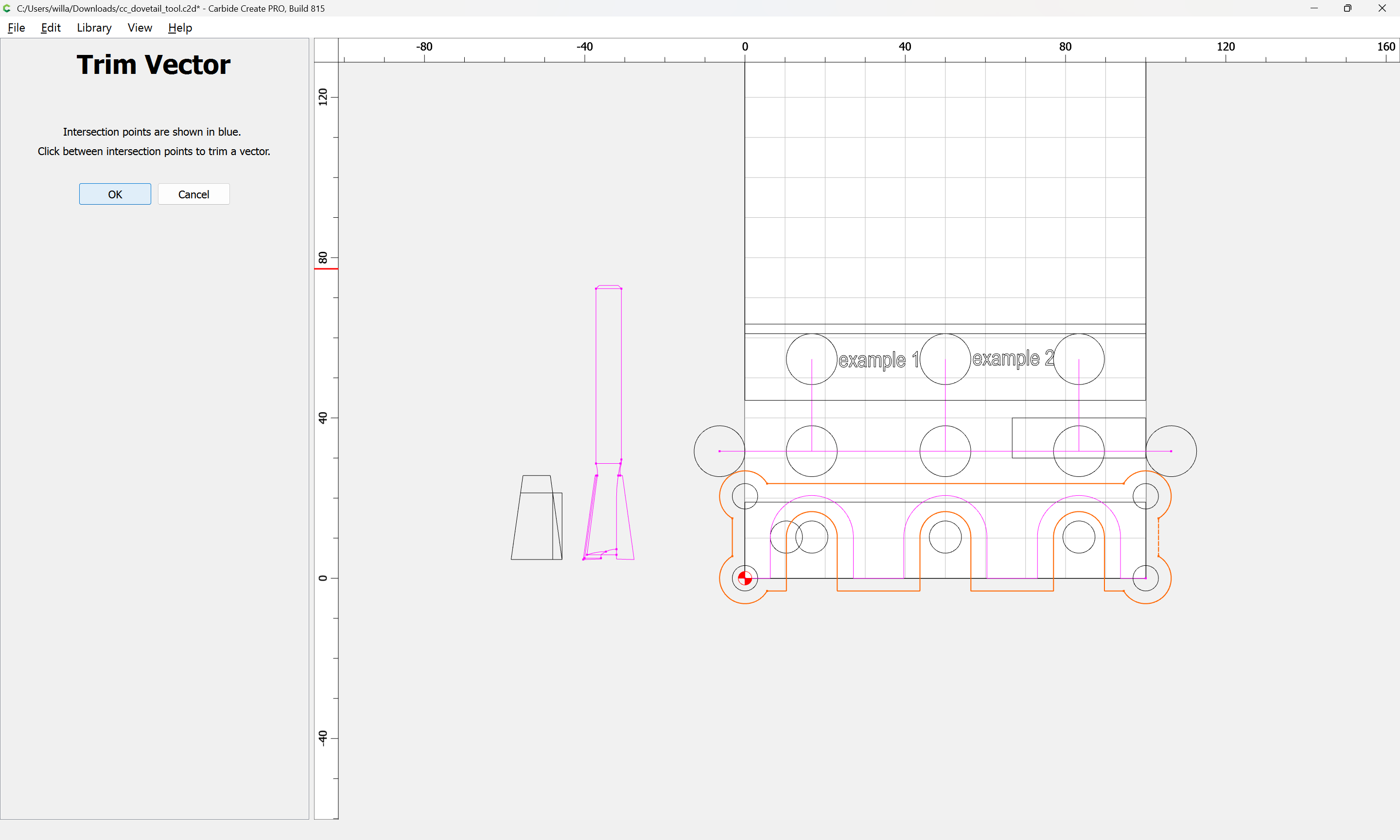
until one arrives at:
OK
OK
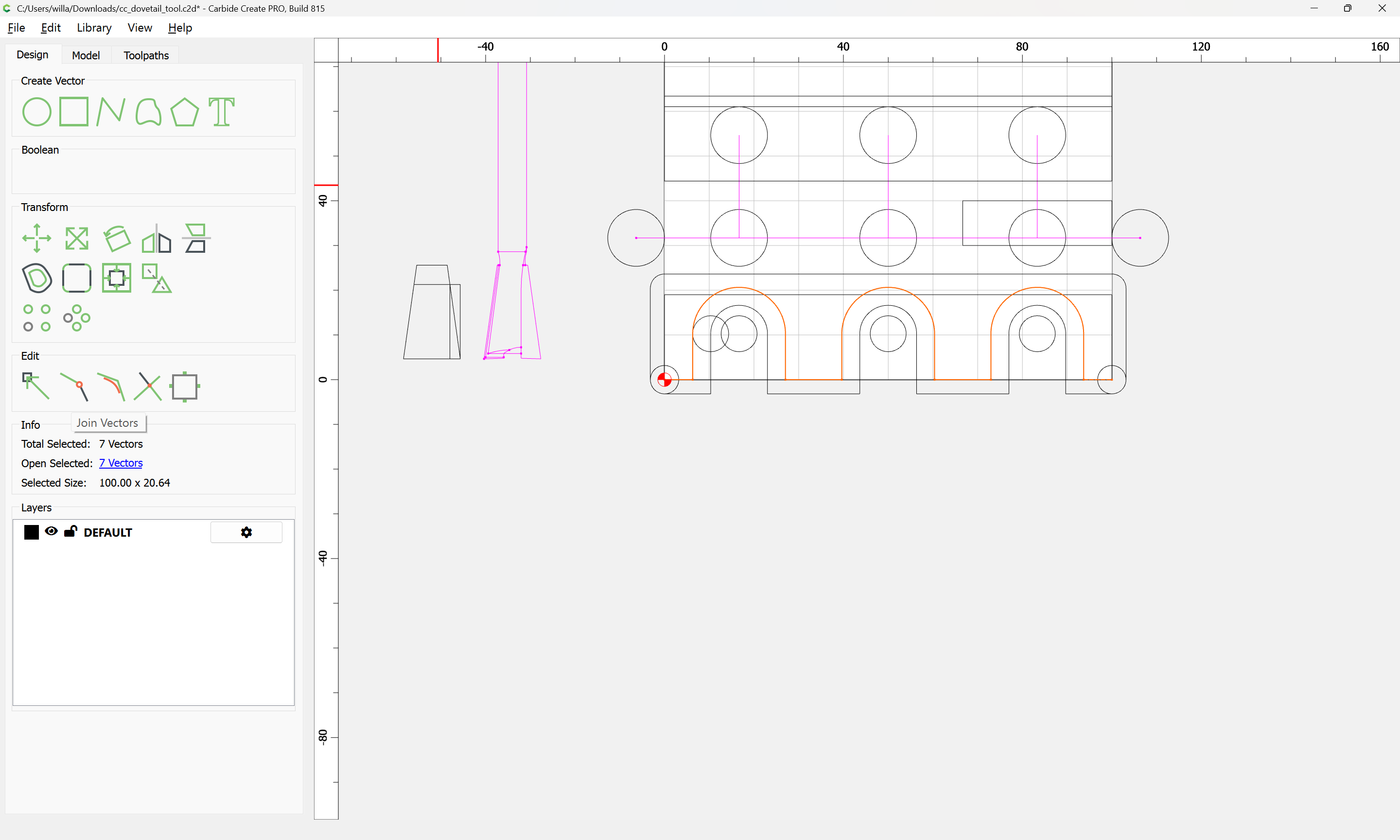
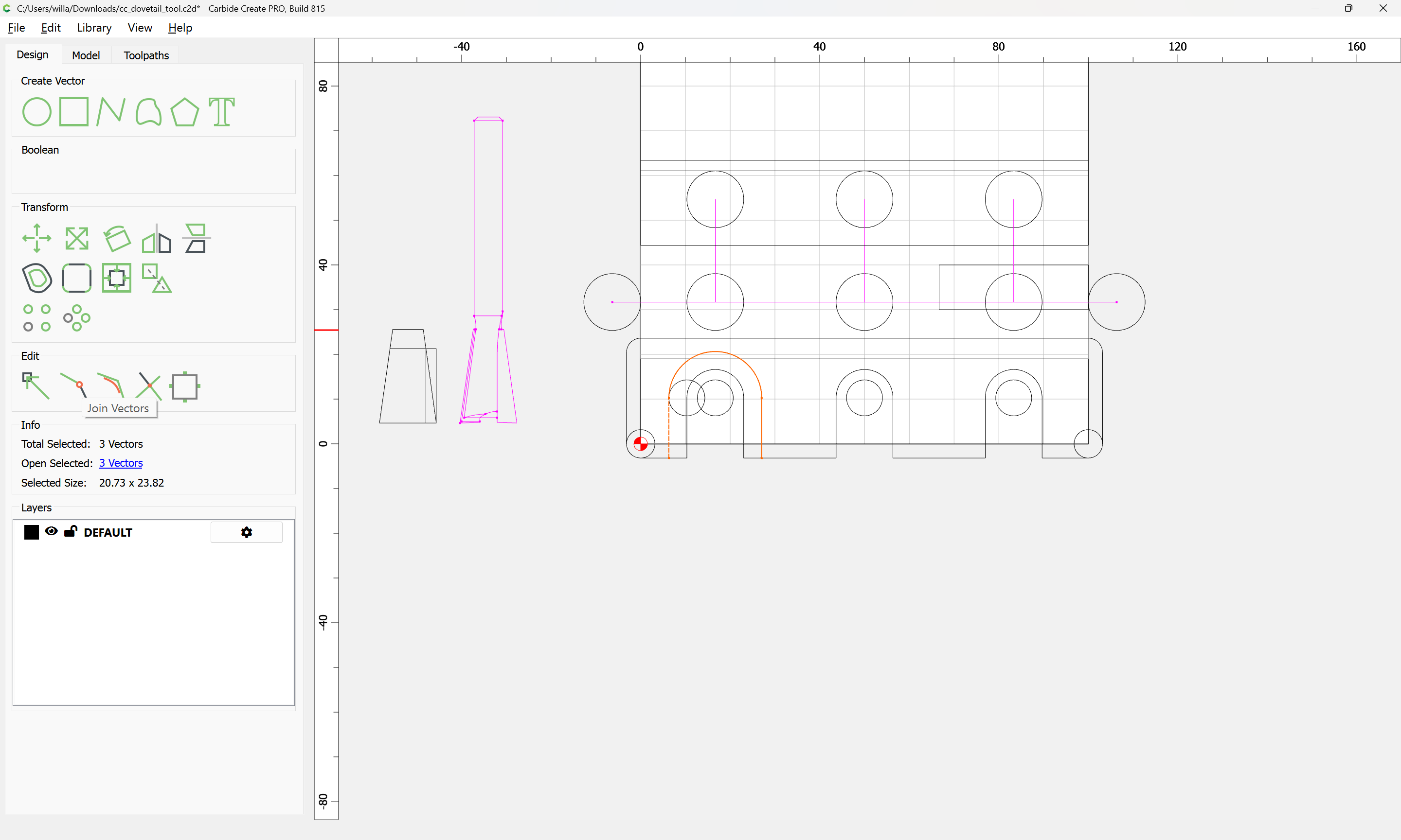
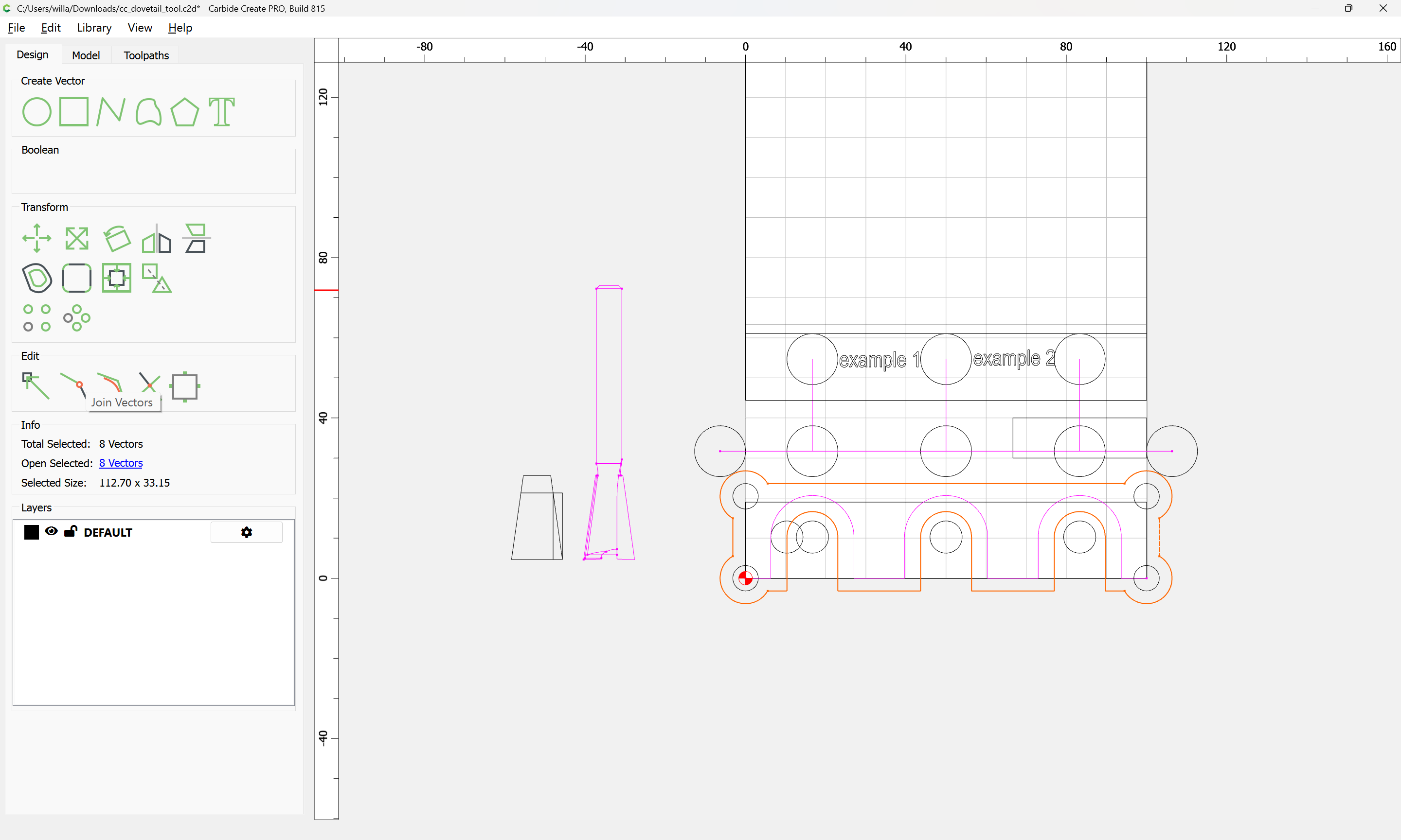
Use Join Vectors:
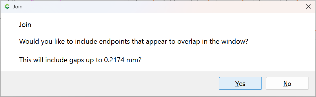
Yes
Then assign a No Offset Contour toolpath for the Dovetail tool which has Depth per Pass set to greater than Max Depth:
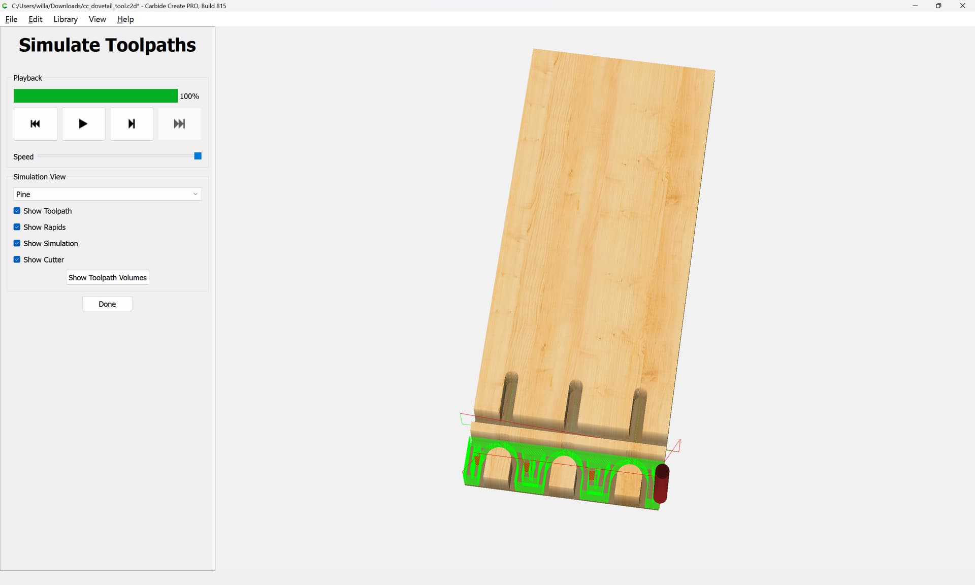
Next up is programming a 3D preview and making a DXF for that.
2 posts were split to a new topic: Using Autodesk Fusion 360 to make dovetails
One concern is that the surrounding pocket should be a bit larger:


OK
OK
Join Vectors
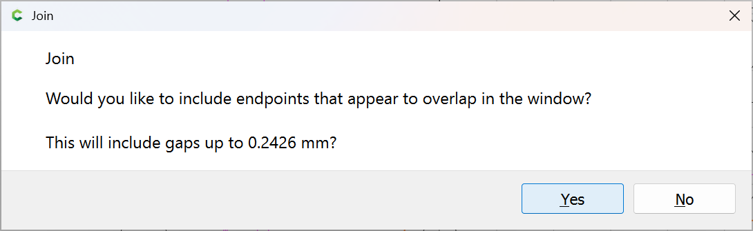
Yes
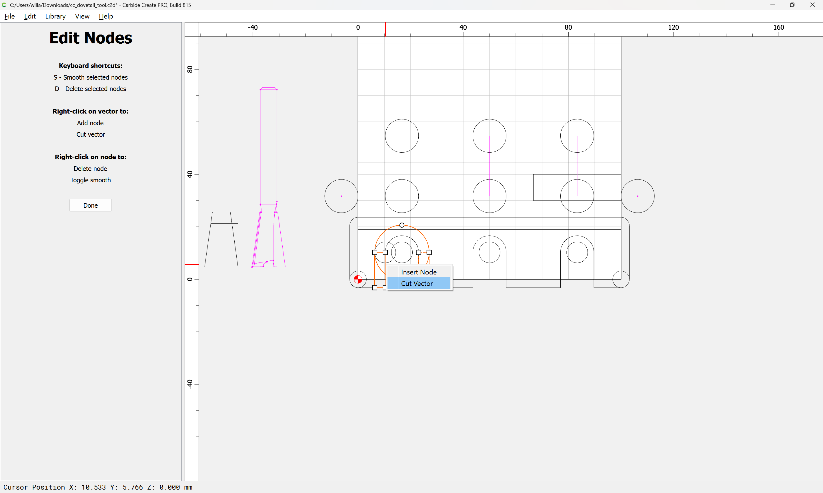
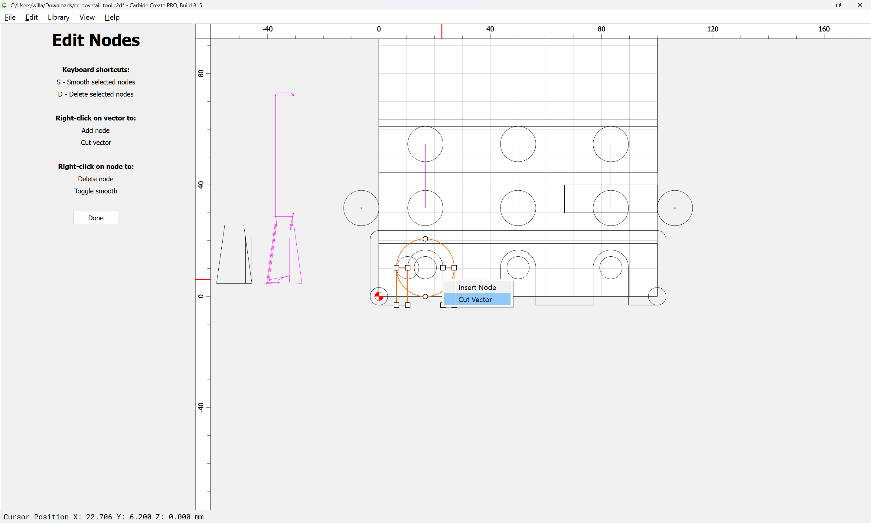
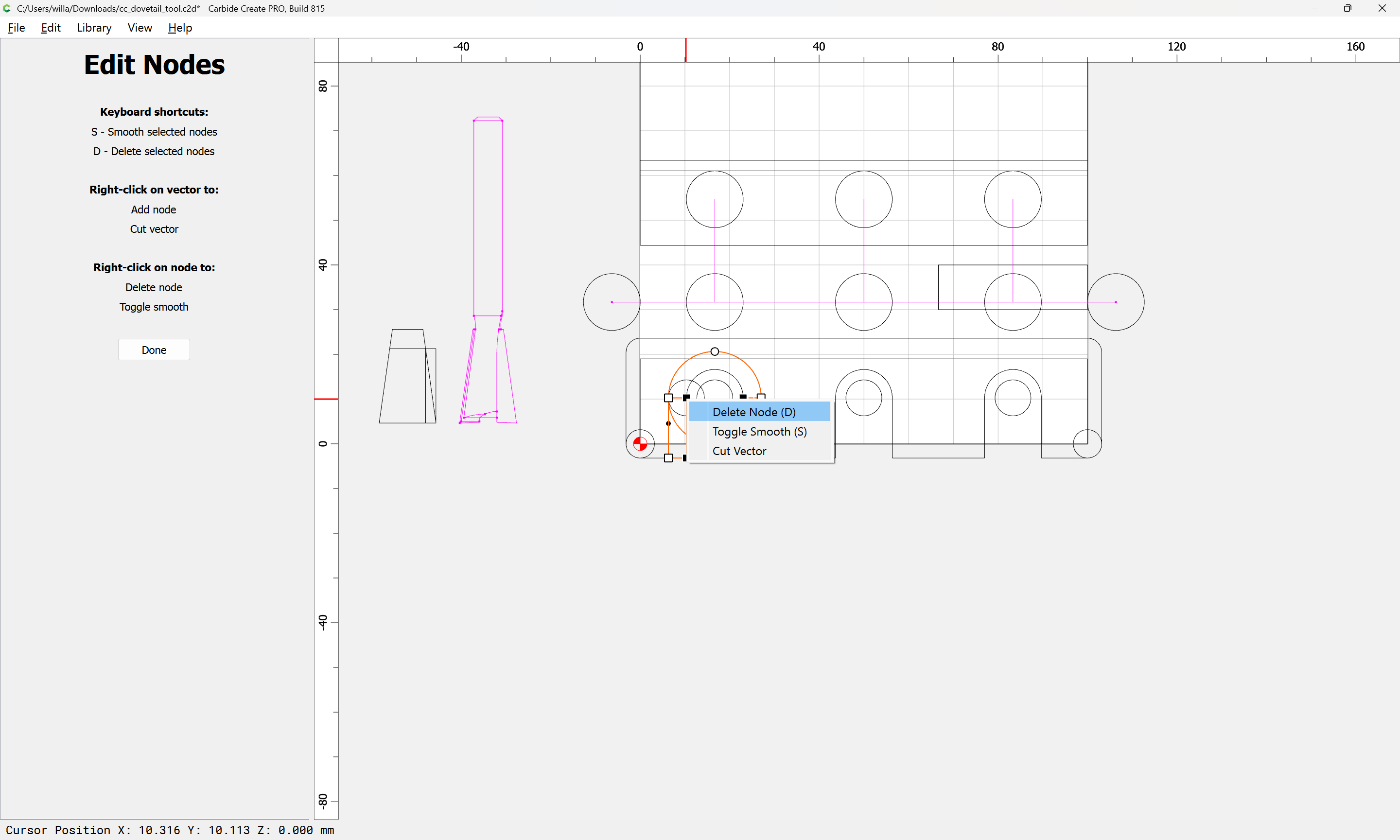
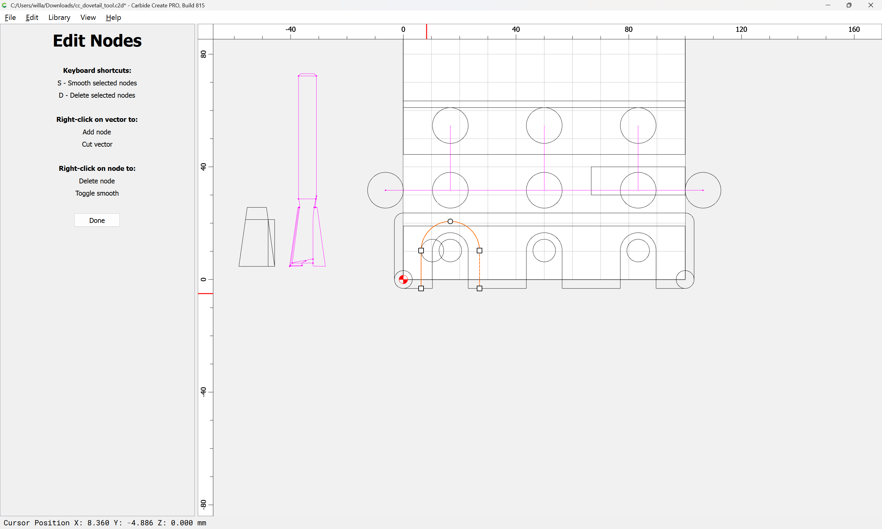
Node Edit:
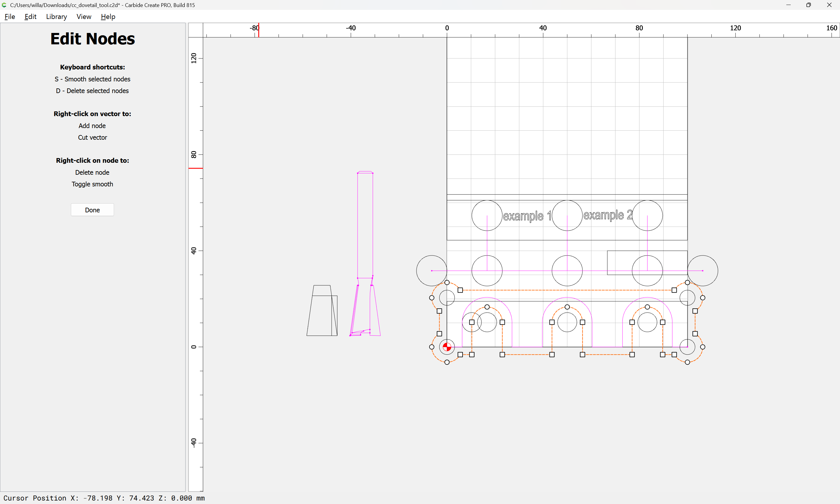
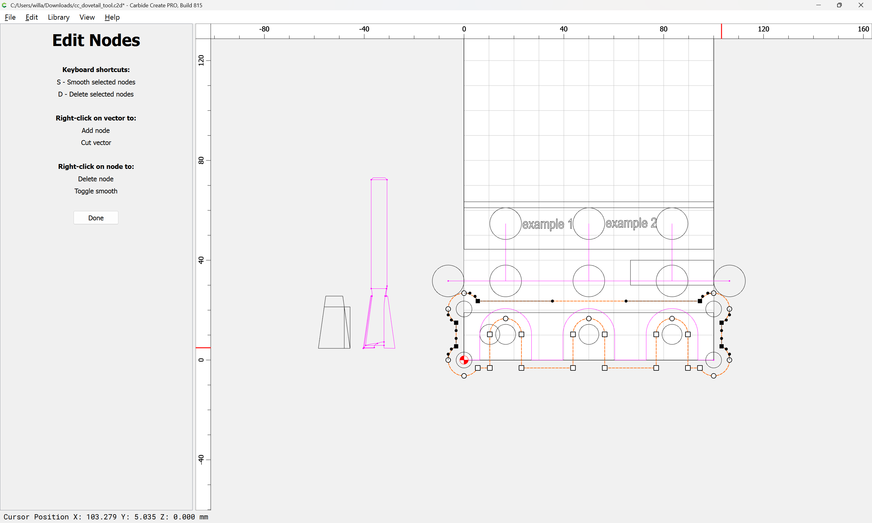
s
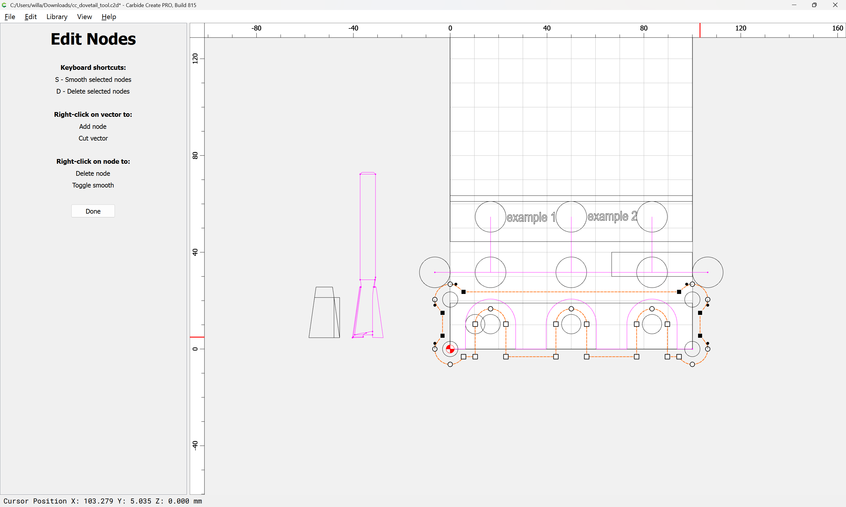
d

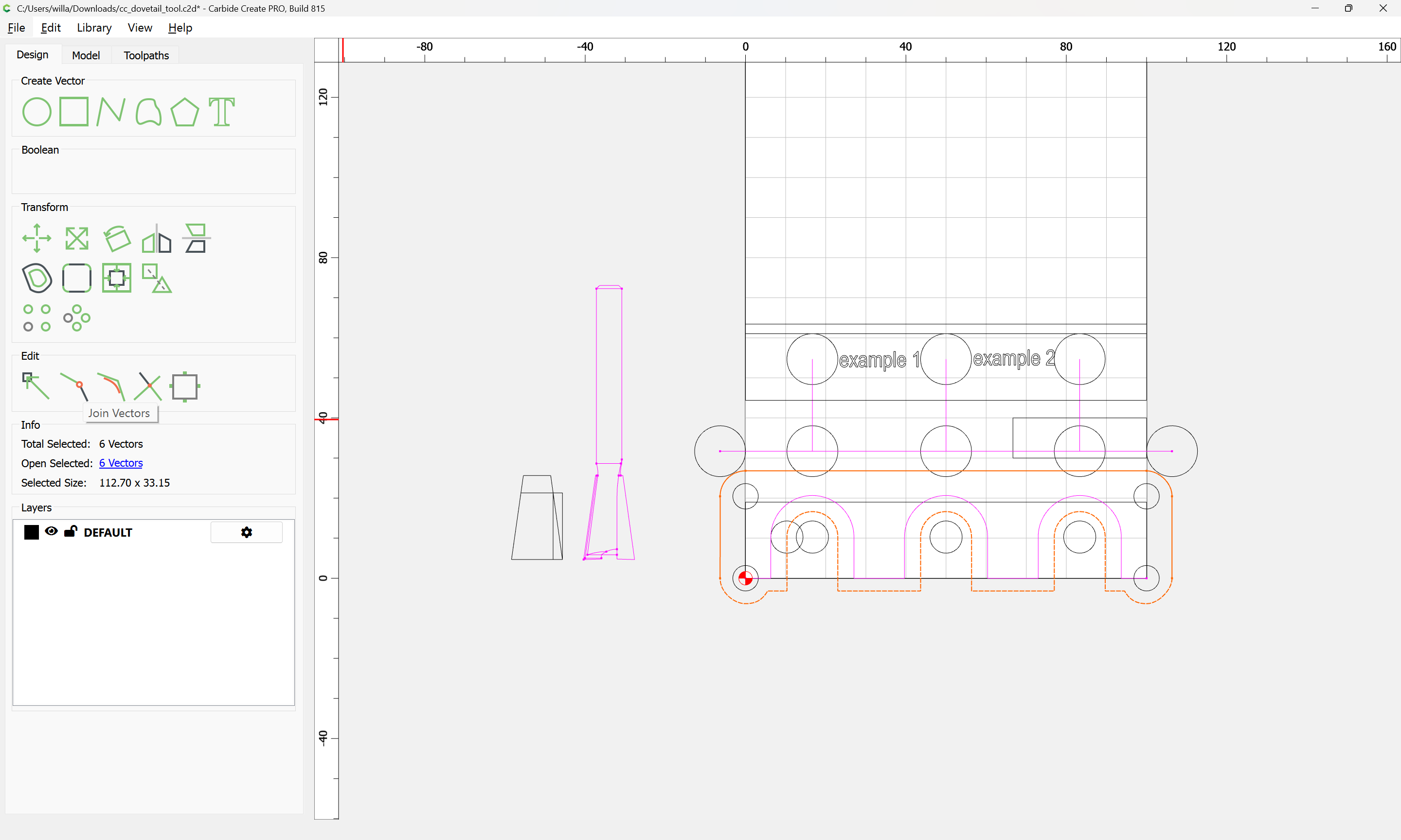
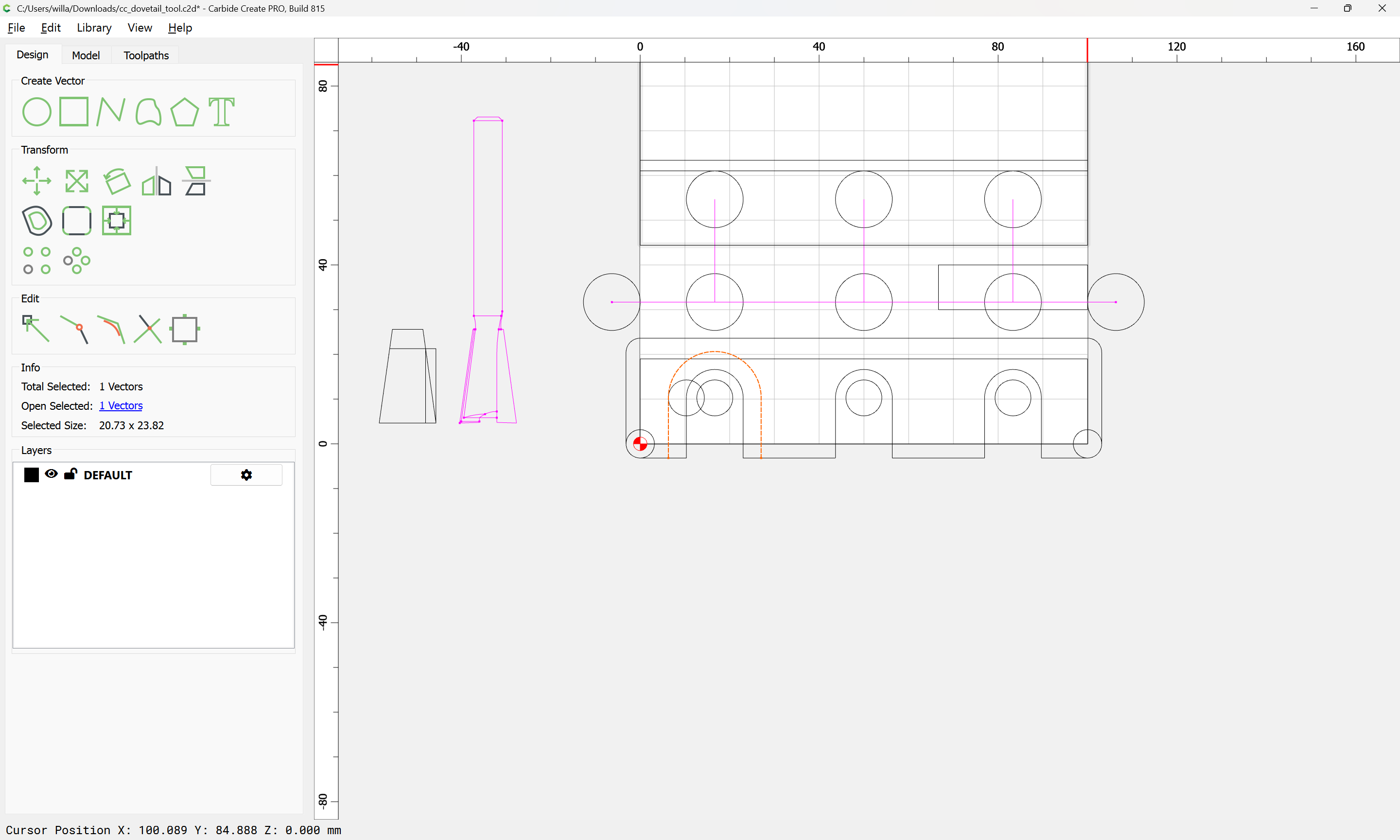
Join Vectors

Yes
The central positions remain the same as the previous iteration, but it will be necessary to offset by:
Dovetail Tool (major) Diameter / 2
and the difference of that and the radius of the narrower width at the top of the cut which is calculated as:
tan(8) * (Stock Thickness * Proportion)
so we add a calculation for that:
and use it to get the first portion of the cut:
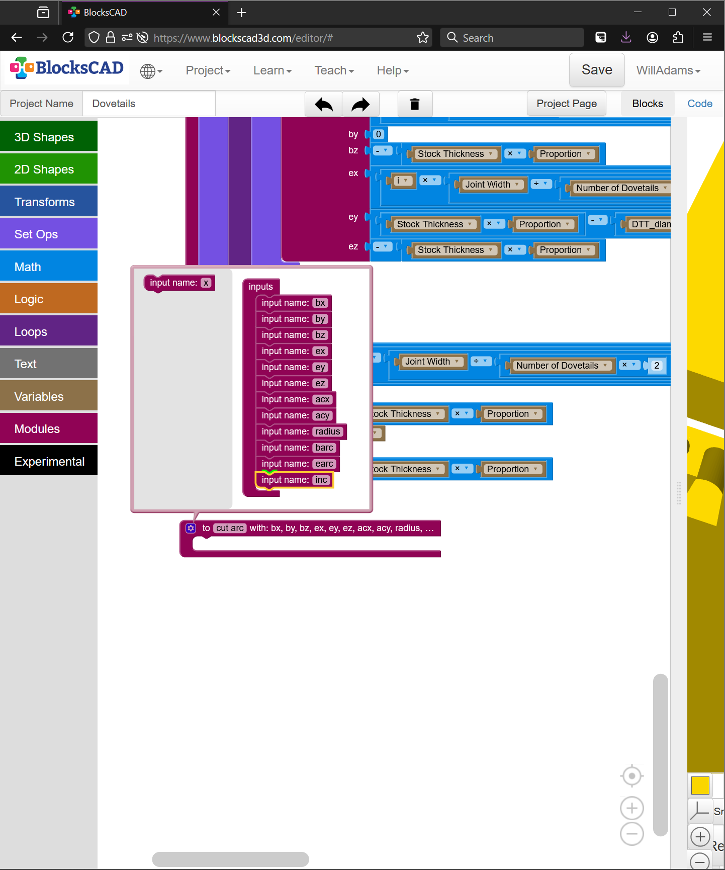
and then apply it to the balance of the cut — which will require writing an arc function, hang on…
Fortunately, I had done such a module already in my current project:
module plot_arc(bx, by, bz, ex, ey, ez, acx, acy, radius, barc, earc, inc){
for (i = [barc : inc : earc-inc]) {
  union(){
    hull()
    {
      translate([acx + cos(i)*radius,
                 acy + sin(i)*radius,
                 0]){
        sphere(r=0.5);
      }
      translate([acx + cos(i+inc)*radius,
                 acy + sin(i+inc)*radius,
                 0]){
        sphere(r=0.5);
      }
    }
      translate([acx + cos(i)*radius,
                 acy + sin(i)*radius,
                 0]){
      sphere(r=2);
    }
      translate([acx + cos(i+inc)*radius,
                 acy + sin(i+inc)*radius,
                 0]){
      sphere(r=2);
    }
  }
}
}
so it should be straight-forward to re-create that in BlockSCAD to use the dovetail_cut module:

which works well:
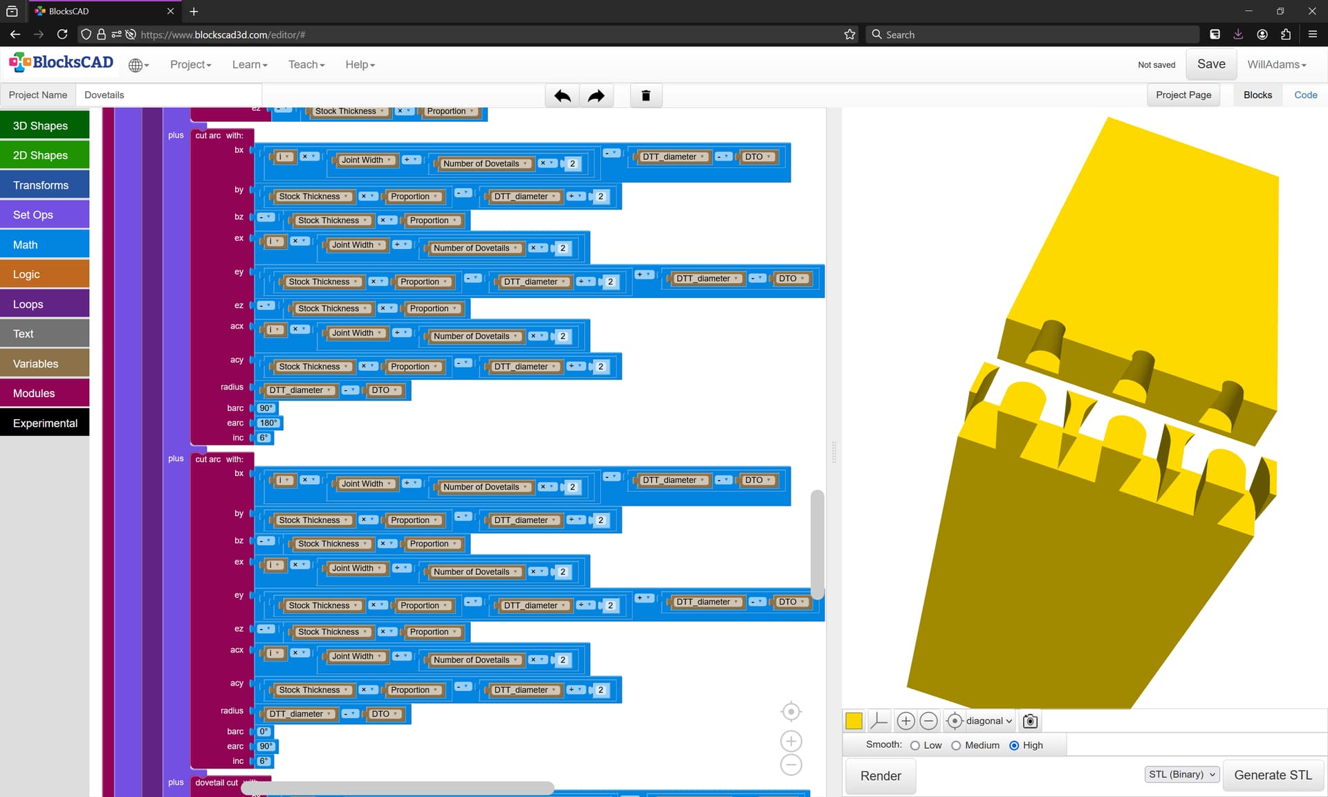
Leaving only the interstices to be cleaned up.
Cleaning those out with a loop and a hard-coded pass leaves some bits floating in mid-air:
File is at:
https://www.blockscad3d.com/community/projects/1941456
Next up is doing this in OpenPythonSCAD:
using:
and the “nimport” feature and sharing the file so that it will be readily available.
Doing this required adding two new commands:
def shiftstock(self, shiftX, shiftY, shiftZ):
and
def addtostock(self, stockXwidth, stockYheight, stockZthickness,
                     shiftX = 0,
                     shiftY = 0,
                     shiftZ = 0):
which then allowed positioning two pieces of stock as required:
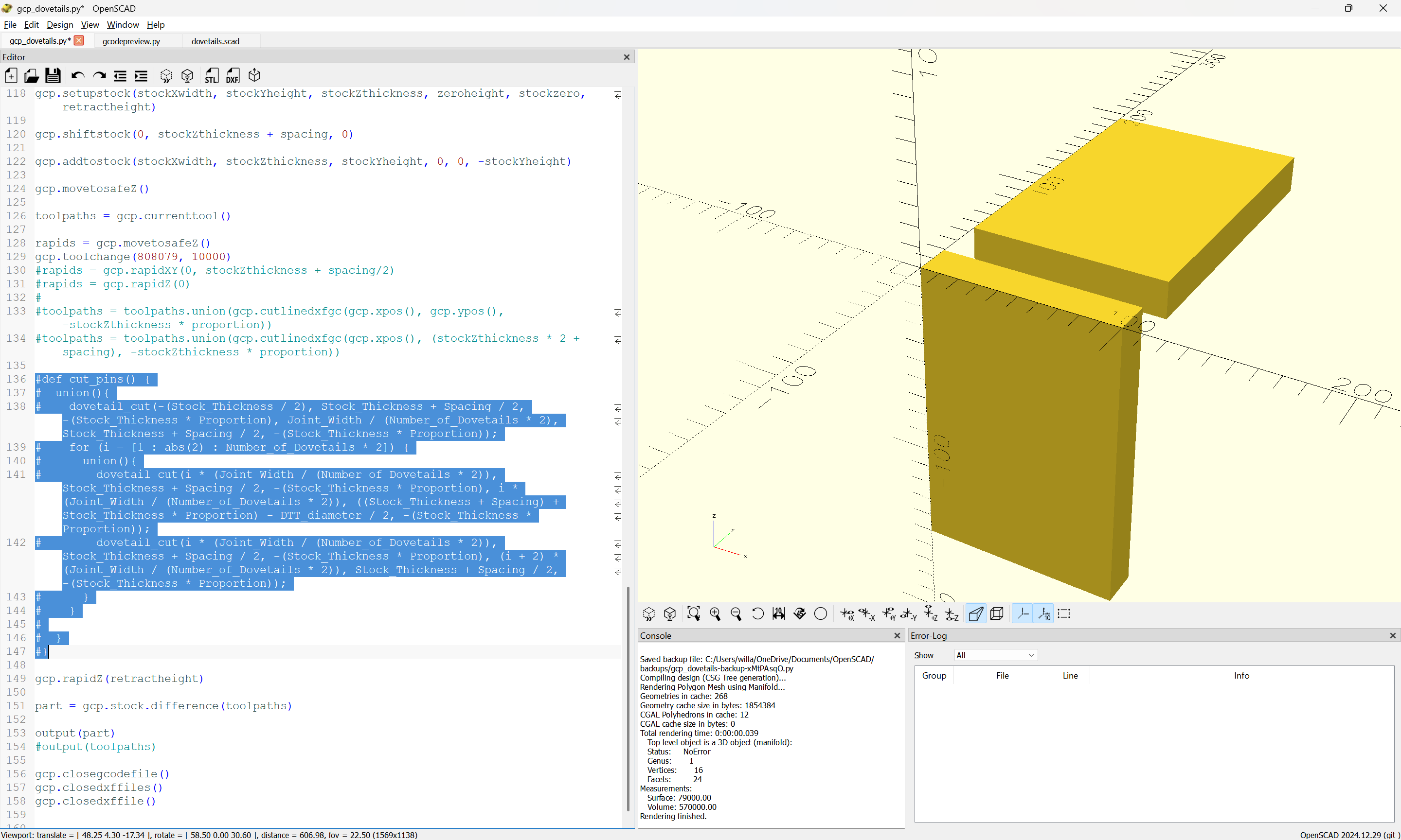
We then write commands in Python for cut_pins and cut_tails…