Done some reading on this, but I can’t find what I’m after.
I have a job that involves facing and a few other op’s with a 6mm end mill. When I come to run my second tool, how can I zero it as I’ve just machined off the face I used to zero the 6mm? Do you create a second setup in F360 with the stock top now coplanar with the part top and zero off the part top?
I’ve read that - it doesn’t involve facing off any material so you can zero to the same surface. If you re-read my description, I’ll be removing that surface during facing, therefore losing my Z reference.
About 5min in he is setting up a second op. on a side face: he sets stock to relative size box and extra material to 0. That’s what I’ve done after my 6mm end mill op’s. Would love some confirmation if this is the right way before I go wreck a nice piece of billet!
Very clever - I like that a lot. It would cover quite a lot of the tools I typically use as well. I’ve got a printer, so I might well knock one up! Thank you!
ya, it works well when you have similar bits with similar flute lengths. They are quick and easy to make so it isnt a pain if you have to make multiple different sets for various jobs.
You can also choose the bottom of the stock box point in setup to zero off of. This lets you zero off the bed or wasteboard, handy for these situations.
You can either choose to zero at the bed near the stock, or some consistent spot on the bed.
Then, you just need to account for anything between the stock and the bed (painters tape/sacrificial board/etc).
When doing it this way make absolute certain of your stock thickness (in several spots) and plug in max measurement. Also, it doesn’t hurt to bump up your heights a tad over stock height to ensure you feed in nice and easy to the material. Not such a big concern for soft materials, but alloys are not forgiving.
When I want to zero from stock top for an overall job that includes a tool change after said top will be gone, I’ve generally approached it by probing both the original stock top and a designated wasteboard probe location before the chips start flying. I just probe both with the first tool and jot down the difference in the machine coordinates of the Z axis.
For subsequent tools, I probe at my designated wasteboard probe location and just enter or jog my recorded offset to recover the original stock-top zero.
This is how I do it too in a situation like this, just be sure you’ve measured the stock accurately or your part will not be the correct size in the z dimension
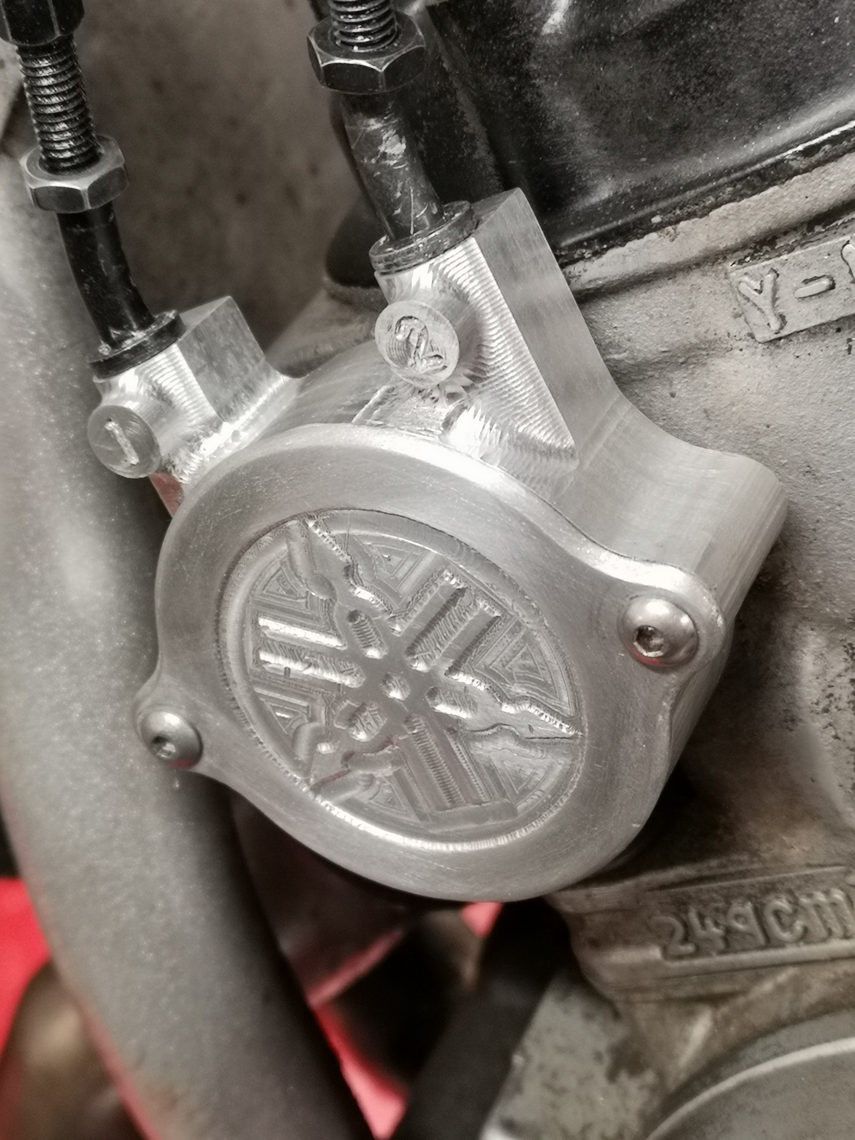
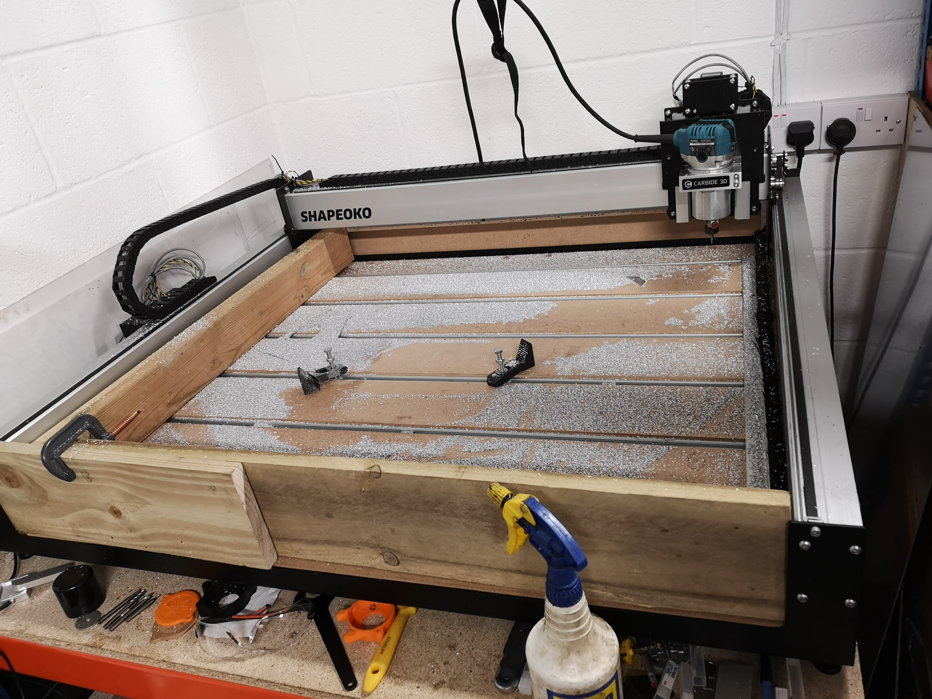
Just a quick thank you to those who offered tips. I’ve done a bit of work on my machine since I bought it but this was my first time using Fusion and running 3D toolpaths. Apart from a lot of chips (that’s a fraction of them - my vacuum is FULL!) I thought you might like to see what I knocked up… It’s a housing and cover for the power valve on my Yamaha TDR250 race bike. You can’t buy these any more and the one I had was getting worn - the holes where the cables enter it become ovalised, which creates slack and the system doesn’t work properly.
Other than deburring the edges with some emery, the finish on the housing is straight off the machine. I gave the top faces of the lid a light rub with some finer grit paper but left the tool marks in the pocket for some contrast. Pretty chuffed to be honest.
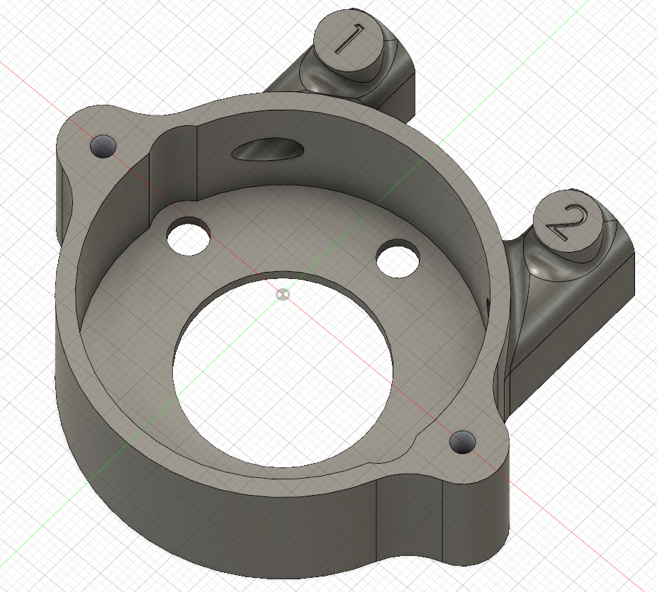
3D horizontal to reduce the height of the faces where the numbers are. (I struggled with picking a good process for this and the paths were’t great.)
2D bore to create the holes
3D ramp to rough out the curved part of the spigots around the numbers
3D parallel to create the curved faces (isolated to that area by picking faces)
Engrave with a 20º bit.
Mount in lathe, face of material on back
Mount in mill to drill cable holes.
Steps 1-5 = 6mm 3 flute end mill, mostly 0.5mm DOC, ~1000mm speed and ~3 on the router. 6 and 7 were 3mm single flute @ 0.25 pitch and 0.25 step down ~500mm travel. 8 was a 6mm ball end. Work holding was superglue and masking tape.
It took me a 3D printed prototype, plus four tries to get to this point (2x Delrin, 2x aluminium) and probably 16 hours between the program and the machine, but to be honest I could thrash it out in WAY less now. Steep but rewarding learning curve!