So I created a new project and it exactly mirrors the settings from a previous one with the exception of a couple additions. When saving the G-Code on the current project it saves fine. when loading into CM it is accepted. When running the job the cuts and depths are completely different!! Is it because I Switched to Pro? If so then how do I revert back? Please HELP!!
Can you upload the two c2d files ?
Any chance you inadvertently changed the zero reference from top to bottom of stock ?
Deutsch.nc (316.5 KB) Zech.nc (189.4 KB)
I have to be missing something, I even tried the old file just to be sure and it worked fine. The original file is labeled Zech.nc
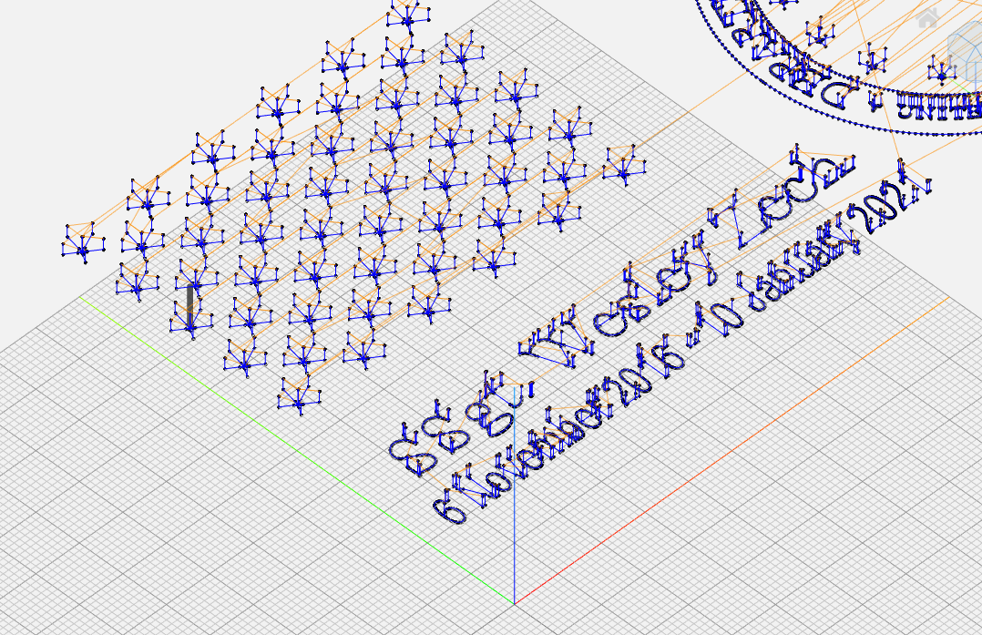
Viewing those two G-code files, they look very similar in how they are setup and how deep they carve (about -0.132" for one, -0.140" for the other)

What are you seeing that is wrong when you run the latest cut ? Do you have a pic maybe ?
Did you zero the same way both times ?

How are you setting your zeroes ?
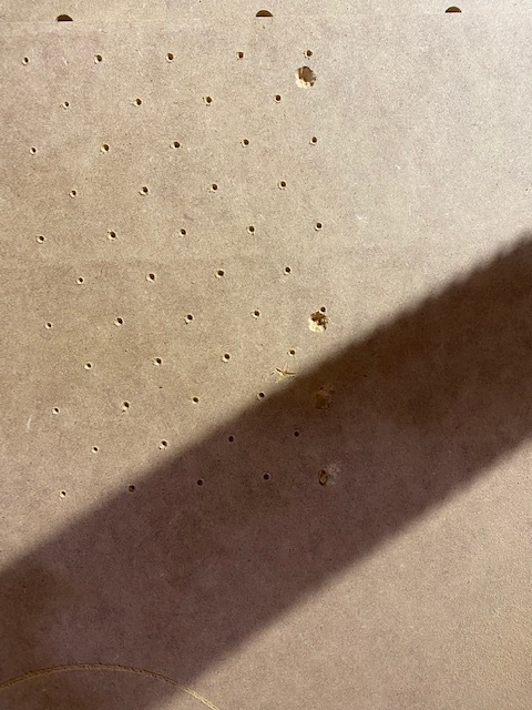
It looks like the Z zero is set higher than the stock surface in that test cut in the first pic.
I checked it all three times and zeroed all of them. I have a bit zero and never had a problem. I even zeroed without the probe. This is it’s first use since converting to the pro version…?
O.K. I created a completely new job and set tool paths, double checked zeros, used the probe, didn’t use the probe. My table, machine, 3/4" waste board and 3/4" project are 100% level! Cleared all offsets and zeros.
Used probe with end mill to zero.
Changed bit to 90V
Set zero one more time with probe.
Loaded new file, started job
started 1/2 or so above project.
Started over
Reset max thickness for tool path
same steps as above
this time cut into project about 1/16"
Started over again
same zero steps but without probe
Gained another 1/16" for a max depth of 1/8"
Started over again by zeroing Z only using probe but placed a 1/8 shim under probe
Same result for max depth of 1/8"
I did four other jobs previously using the proper steps outlined in all the YouTube videos you have. Last four projects have been using 3/4" stock and worked perfectly!! I’m at the end of my rope here!
Which Z axis do you have?
Can you just Vcarve a small test square to see if it’s just an issue with THAT project?
Can you share your grbl $$ settings?
2 Likes
In addition to @neilferreri’s questions, could you please:
- upload the project file itself (the *.c2d, not the nc file)
- re-upload that latest “Deutsch.nc” file, for some reason the link does not work
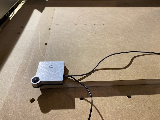
When you mentioned - confirm you do not have a BitSetter
This:
would tend to tell me you had the zero set of stock bottom but zeroed on the top.

Any chance you have the machine configured for the belt driven Z axis?
2 Likes
Since the project and G-code file are ok, chances are Neil is right and it might be something with the Z axis configuration.
In CM, in the Settings page, can you click the open log window, then go back to the “MDI” tab in CM, and send $$ in the command line there. Then observe the output in the log window, and report about the value of the $102 parameter. Should be 200
Not the first time I’ve used it and it worked perfectly with zero issues. Only thing that has changed is that I converted over to the pro version of CC. I’ve checked and rechecked every setting, I went back and watched every tutorial available just to make sure I am proficient at the process.
Rest assured it has nothing to do with using “Pro” mode or not in Carbide Create, otherwise it would show in the generated G-code, and it is ok.
It is however possible that the Z axis settings were inadvertently modified, and this is worth a check anyway (using the procedure I mentioned), as this need to be correct for the rest of the investigation to make sense
1 Like
$$
$0=10
$1=255
$2=0
$3=2
$4=0
$5=0
$6=0
$10=255
$11=0.020
$12=0.010
$13=0
$20=0
$21=0
$22=1
$23=0
$24=100.000
$25=2000.000
$26=25
$27=3.000
$30=1000
$31=0
$32=0
$100=40.000
$101=40.000
$102=200.000
$110=10000.000
$111=10000.000
$112=1000.000
$120=500.000
$121=500.000
$122=270.000
$130=845.000
$131=850.000
$132=95.000
ok
$#
[G54:0.000,0.000,0.000]
[G55:0.000,0.000,0.000]
[G56:0.000,0.000,0.000]
[G57:0.000,0.000,0.000]
[G58:0.000,0.000,0.000]
[G59:0.000,0.000,0.000]
[G28:0.000,0.000,0.000]
[G30:0.000,0.000,0.000]
[G92:0.000,0.000,0.000]
[TLO:0.000]
[PRB:0.000,0.000,0.000:0]
ok
$G
[GC:G0 G54 G17 G21 G90 G94 M5 M9 T0 F0 S0]
ok
2 Likes
Allright thank you, it is setup correctly then.
Next up is
- checking if you get correct movements when manually jogging: does the Z axis move exactly 1inch when you jog up or down 1 inch ?
- trying the simplest possible cut as Neil proposed (a simple square contour, of known depth)
2 Likes
O.K. so to make a long story short, the issue fixed itself. I switched everything over to my laptop and surprisingly it is now working perfect… thank you all for your help and guidance I learned a lot.
1 Like
One thing I forgot to mention is that BitZero does not work consistently enough to even use it. It makes inaccurate depth cuts as apposed to doing it the old fashion way which works properly every time.
1 Like
Toby, does your BitZeroV2 actually move while it is probing XYZ? Can you hold it (perhaps with double sided tape) while it is probing and see if that makes it more consistent in your situation?