Heya - I’ve really come to love the combination of my Nomad and Fusion360 cam - there’s a lot more work to do over meshcam, but the control you have is pretty amazing.
One thing I haven’t been able to figure out, however, is how to get rid of vertical “draft angle” when milling discs, pockets, etc of any substantial depth.
I’ve had this happen on renshape, and just now with HDPE - 1/2" total depth, using a pretty sharp single-flute zirn end mill (1/8"), .005" chipload.
When milling deep pockets using 3d pocket clearing or adaptive clearing, I find that vertical surfaces ultimately end up with about 0.5-1deg of draft angle from the top of the stock (zero) to the bottom of the cut (ie z -0.5"), even when followed by a contour pass to cut off any tool deflection hanger-on material.
Any tricks, or secret things, that you need to set or check to make sure that vertical surfaces are 100% vertical? When cutting discs, they end up coming out as cones, which isn’t great.
Thanks!
Chris
That “draft angle” is due to deflection in the tool - it’s not “true” draft…it’s a defect, not a design feature .5" is pretty deep for a single flute ⅛" tool. If this was a misalignment with the Z axis, you wouldn’t get a cone. I’d suggest maybe multiple finishing “spring passes.” HDPE is a bit springy to begin with, and the deflection at the tip of the end mill will be furthest. What’s the cutting length of the tool you’re using? The upper parts of these tools don’t cut very well, and you may be getting rubbing there that is driving out the bottom of the tool?
The fact that it comes out as a cone says to me that its not a tramming issue where the table and the spindle are not perpendicular to each other.
It does feel to me like you may be cutting deeper than the flutes on the end mill or pushing the end mill so hard it is deflecting. Do you have the same wall problem when cutting in a straight line in either the X or Y direction where tool deflection would probably not cause this?
Also your Depth of Cut would be good to know - I am fairly sure you aren’t cutting 1/2” in one pass - but it doesn’t hurt to ask.
I did 3d pocket clearing, which is a top-down, multiple-pass strategy (0.35 stepdown), followed by a contour pass (again, top-down) - so I would think that if it were tool deflection or material spring, all but the bottom most portion of the part would see the draft/growth. The vertical surfaces saw a cutter pass it multiple times. Tool stick-out was kept as minimal as possible and still reach the bottom of the matl.
I left 0.002 stock remaining on my pocket operation so the contour/finish pass had a little something to bite into. At the top, you could hear the cutter picking up just a small amount (probably 0.002) and at the middle (abt 0.25" depth) the cutter was working progressively harder as it approached the bottom of the piece (0.5"). But on this pass, I would say that it never sounded like it was working any harder than a finish pass should.
I do agree, tho, that 1/2" deep pocket on a 1/2" stated-flute-length tool is probably optimistic. The single flute is hard to read by eye as to whether it’s tapered in any way as it reaches the shank. I’ll double check that.
I spun my discs on a lathe to square them afterwards, so the evidence is gone now - but I remember that the top of my piece (about top 1/3rd, so maybe 0.187 ish) had a nice finish, showing no tool marks at all on the vertical surfaces, with layered tool marks showing as the tool progressed deeper. Maybe I needed to think about this the other way, in that those tool marks should be showing on the entire surface, and that the top portion was so clean and nice because the shank was rubbing and therefore polishing the upper portion.
For my pocket clearing, I followed Winston’s recipe for HDPE where he targeted a .005" chipload:
For my finish, contour pass, I used 0.0025" chipload.
I always worry about too-light of chip load on plastics - I had a devil of a time with acrylics one time because I was taking a big enough bite, the tool overheated, the plastic melted into a ball on the cutter, and wrecked about 3 cutters.
Just for fun, this is the design - workpiece is 8x8x0.5" HDPE, three passes, 3d pocket to rough out the discs (and center hole), 3d contour to make sure the verticals are “true and square” (not), and then a final pocket operation to cut an axial-face groove concentric to the center hole and outer diameter.
This is a transmission differential setup tool (NLA from mfr) where I need to project the ring-gear pitch diameter into free-space along an axis through the differential bearing carrier bore holes in the side case…to check the pinion depth per the mfg spec.
The small disc drops into the bearing carrier bore in the side of the case, and the large disc is a reference diameter which then sits in free-space in front of the pinion head. A piece of 2" OD steel tubing is cut to length and faced on both ends and fits into the axial slots/bores to extend the axis through the case and position the large disc in place.
If I did the math correcty, 0.5 to 1degree over 0.5" height is an offset of 0.004’’ to 0.008’’ between the top edge and the bottom edge ?
It’s a silly idea but I thought I would ask anyway: have you checked your runout ?
0.008’’ would be a huge runout to have, especially on a Nomad spindle, so that must be something else, yet it’s still good to double-check ?
EDIT: that’s assuming a single full-depth finish pass. I can’t tell from the pic.
Finish pass is 3d contour, same 1/8" single flute (no tool change), same 0.35" stepdown, same 0.005" chipload, but set with REST machining and prior op (3d pocket) left 0.002" stock remaining.
Haven’t checked runout - don’t think runout would result in a cone shape draft on circular parts.
Right now I’m thinking it’s rubbing of the cutter/shank region. Need to check the cutter shape. Cutter I’m using is this one:
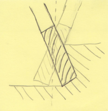
For the sake of the argument, what if the tool axis was wobbly, and one made a single full depth contour cut against the walls ? Looks conical to me (EXTREMELY exaggerated below)
Oh. Reading the original post it was not clear to me whether the resulting piece was a cone (disc) or an inverted cone (pocket). Forget my post then (and there is no chance a Nomad would have such a large runout anyway, that was me thinking out loud)
Right. Curiousity triggered. Apologies for the odd numbers but thats what happens when the country you live in is 1/2 metric and 1/2 imperial.
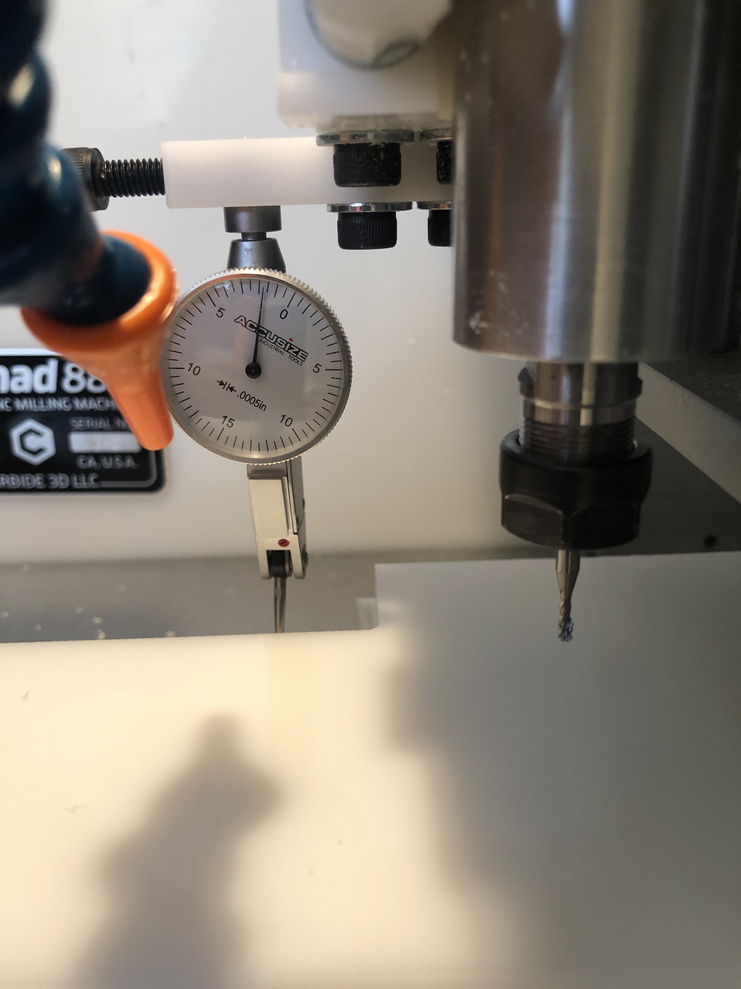
Just happen to have a big block of 1” HDPE strapped down to the Nomad and am slowly carving blocks out of it so thought I would measure my last cut.
The settings:
-Contour cut, no finishing pass
-Bog standard C3D #102 1/8” 2 flute end mill. -Note had to clear the 1” stock so end mill is sticking out quite far from the collet.
-10,000 RPM, 100ipm, 0.04” Stepdown.
Faced the top of the stock down so there is 0.71” total stock height. Cutting right to the limit on the flutes.
So got in there with the indicator this morning. 0.0015” ish top to bottom on the straight cut (0.12 degrees). In the corner where you might expect extra deflection 0.002” (0.16 degrees)
0.35” Stepdown is pretty hefty but if it works it works.
If your finishing pass on HDPE is not taking off enough material per tooth it can squish itself out of the way instead of cutting, providing little benefit.
Since HDPE melts at around 130C, perhaps you see an angled edge since the warm/hot cutter spends more time touching the upper part than the lower part.
In general, climb cutting is preferable on a sufficiently rigid machine such as the Nomad. Climb cutting tends to do two things relevant here: pull the work to the tool in the travel direction, which can be a real issue on a machine with excess backlash, and cause the tool to deflect away from the material, leaving a slightly sloped surface.
Aside from flexability and play in the spindle, which will be a problem no matter what you do, the tool flexing is proportional to the thirs power of stickout from the collet. Double the stickout, 8 times the deflection for a given load, without considering variation in the tool cross section, of course.
Climb cutting tends to give a more uniform finish than conventional, but, again, the load on the tool tends to deflect the tool normal to the tool path away from the material.
Conventional cutting tends to deflect the tool backwards along the tool path parallel to the material. For a finishing pass, this MAY help. The drawback is that the finish may suffer.
You might try finishing in conventional cutting rather than climb to see if it helps.
Excellent point. Note all my HDPE cuts above were done in conventional and from what I have read (and I think @wmoy mentions in his video) softer materials finish better in conventional.
Could also do a finishing pass with a 0.25” dia. tool if you have the 0.25 collet and end mill which should minimize the tool deflection and probably eliminate the flute length problem at the same time.
Yep - did that - .002" stock remaining on 3d pocket, 0 stock remaining on finish contour.
However, if my roughing at the top left .002 to bite off, but tool deflection flared it out at the bottom, that could mean that I had something like .005 or .008 stock remaining at the bottom (despite the setup saying only 002) - which is a bigger bite than the stock to leave would indicate in real life and perhaps what I thought was a finishing operation (at the top) became a roughing operation (at the bottom) in real life.