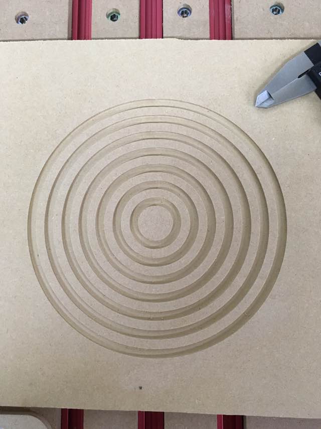
I’ve created two files, one containing seven concentric Squares sized from 1" to 7" in size and the other with seven concentric Circles, again from 1" to 7".
The photos are only included for reference. The measurements are below.
Thanks for the note. I used a 1/4" endmill and cut outside the path on both test cuts. If I cut “on” the path would that not just give me 1/8" smaller circles and squares?
Yes, it would, but the question is whether you cut outside for the squares and on the lines for the circles. That would produce similar results to what you got.
I used a 1/4" endmill and cut “outside” the path on both test cuts. That’s the confusing part. If one is off, both should be off. If one is near perfect, the other should be too.
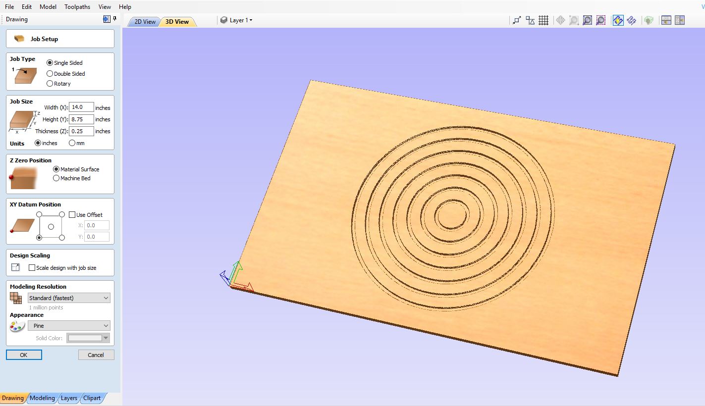
I use Vectric VCarve Desktop. It generates.CRV source files and they aren’t uploadable here. I’ll be happy to follow any suggestions for the files you need.
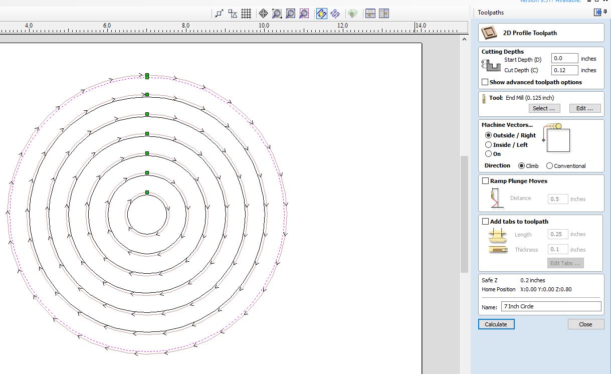
It looks like your endmill is setup as 1/8 rather than 1/4. Running outside the path, that will put a 1/4 tool 1/16 closer than it needs to be. Measured across the diagonal, that would be an error of 1/16 * 2 = 1/8.
This may be @RickT’s first post, but he was DEAD on. Thanks Rick!!! It was right in my face as I was making the pics for uploading. I ran the Squares Test first and when I created the Circle Test, I entered the 1/8" endmill on the 1" circle and then just duplicated it to the other six circles.
I owe you a beer, Man! I can’t tell you how relieved I am to find that the problem wasn’t with my machine. Also, how embarrassed I am. What a blunder. I should have seen that myself.
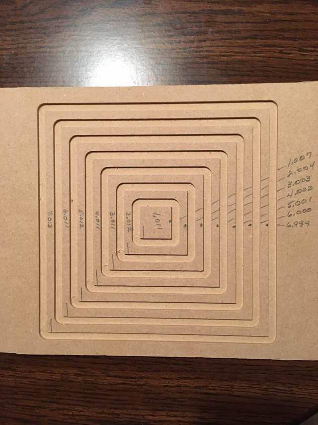
 I had a typo on the depth. And the glare at the top is hiding the hand printed sizes.
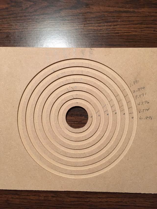

 I should have seen that myself.