I have tried everything I can to get a simple 3D model for a turtle shell and I get nothing. I have CCPro, and have listened to the “tutorial” on youtube by Chris Powell to the extent that I think I can say the whole tutorial by heart!
Somehow, no matter how many times I follow what I think he is saying, I still get either a flat turtle, or a complete cutout of all the parts, which is no good either.
I must just be the dumbest follower of these “tutorials” in the world. Just so frustrating.
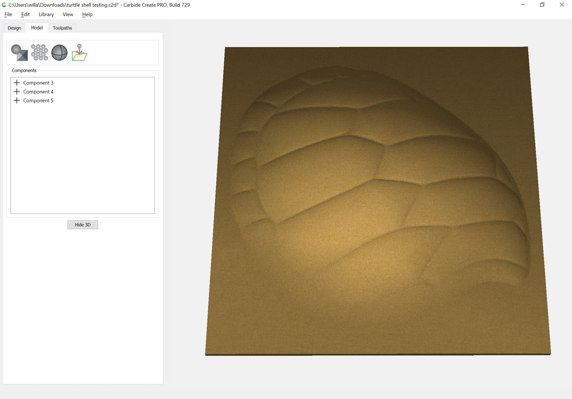
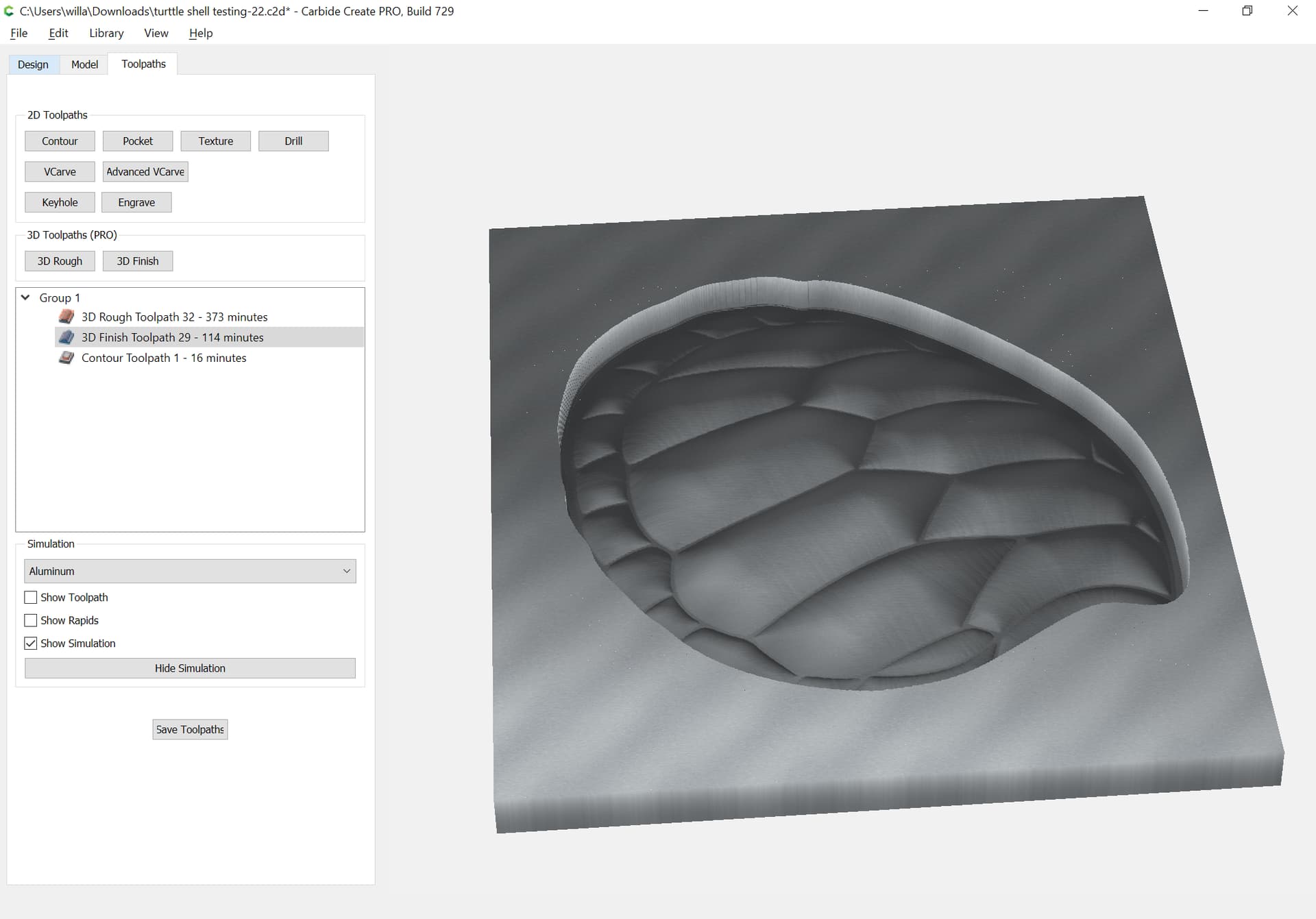
That appears to be what I’m looking to get, but I’m so tired at this point, I’m going to wait till tomorrow to try to understand.
One of the challenges I have, and I guess it’s just my computer and eyes, but trying to read the settings on your posting on the left side, it pretty small and even trying to zoom in only increases the written text, and not the actual settings your are changing on each screen. That may not make sense, but I’m probably just too tired tonight.
If you click on the image, you should then get an option “Original Image” which will open the image itself and allow you to zoom in and out and pan around the image.
First off…THANK YOU…again. This is what I’m looking for.
Questions:
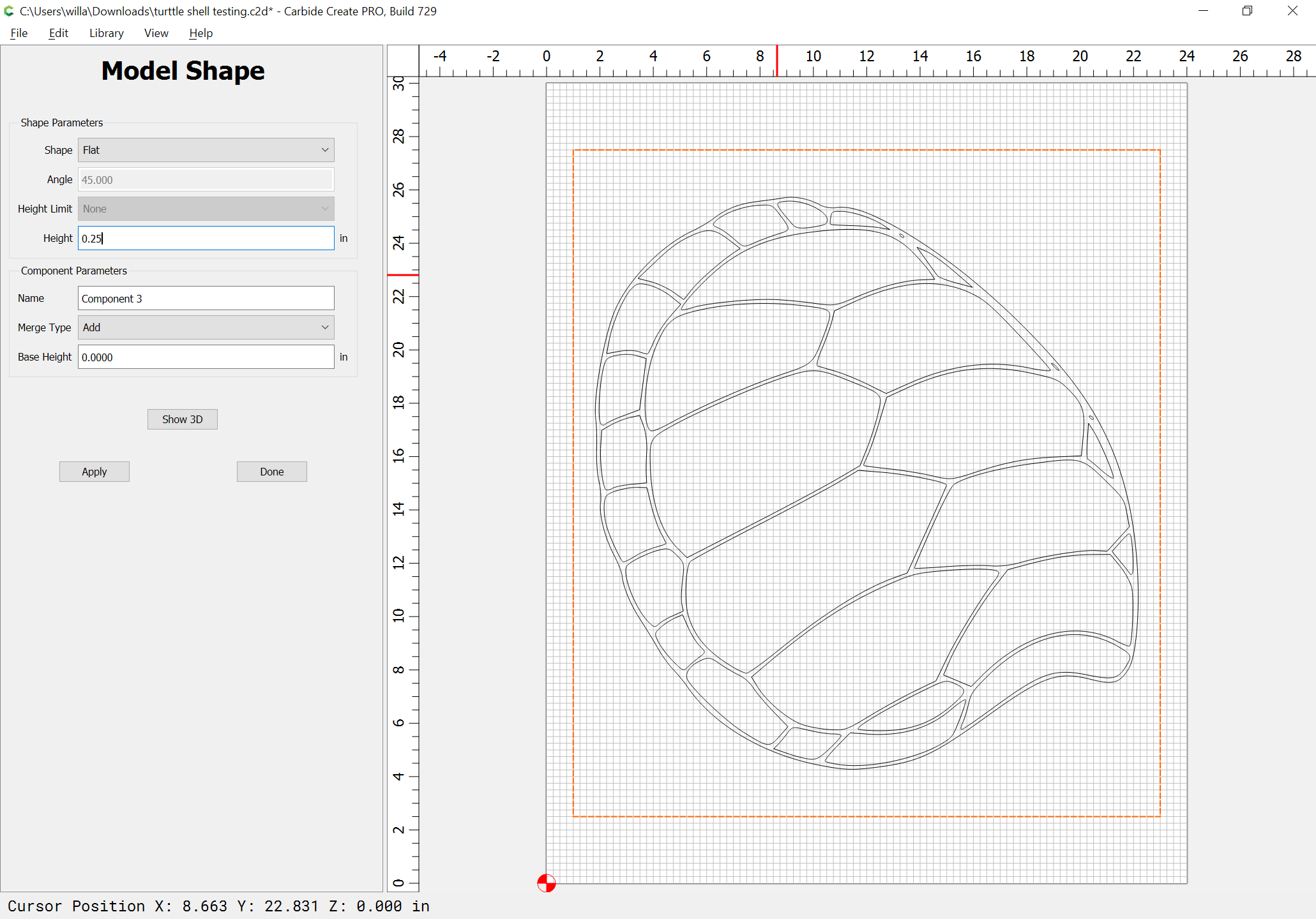
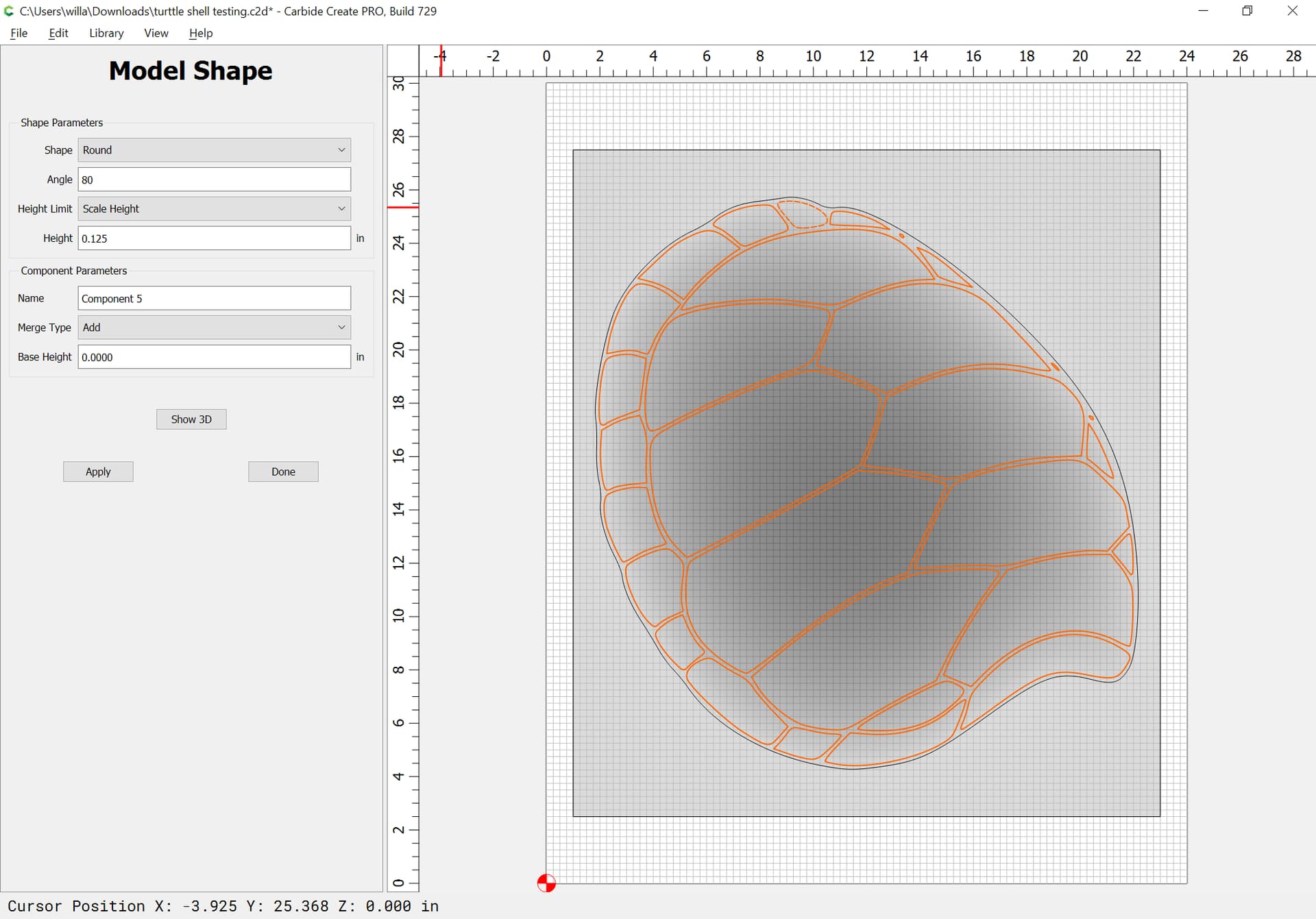
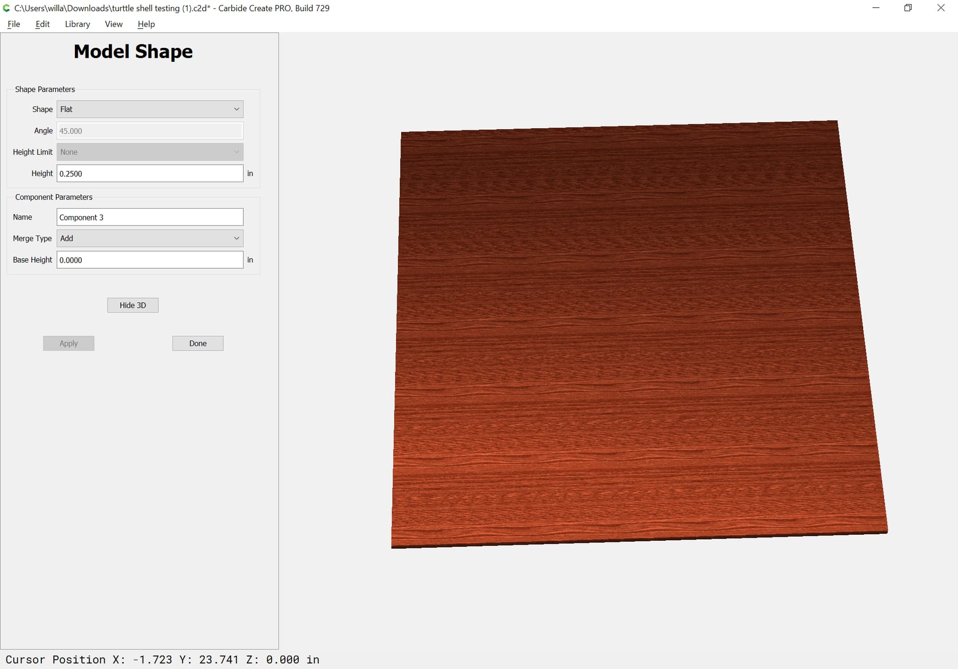
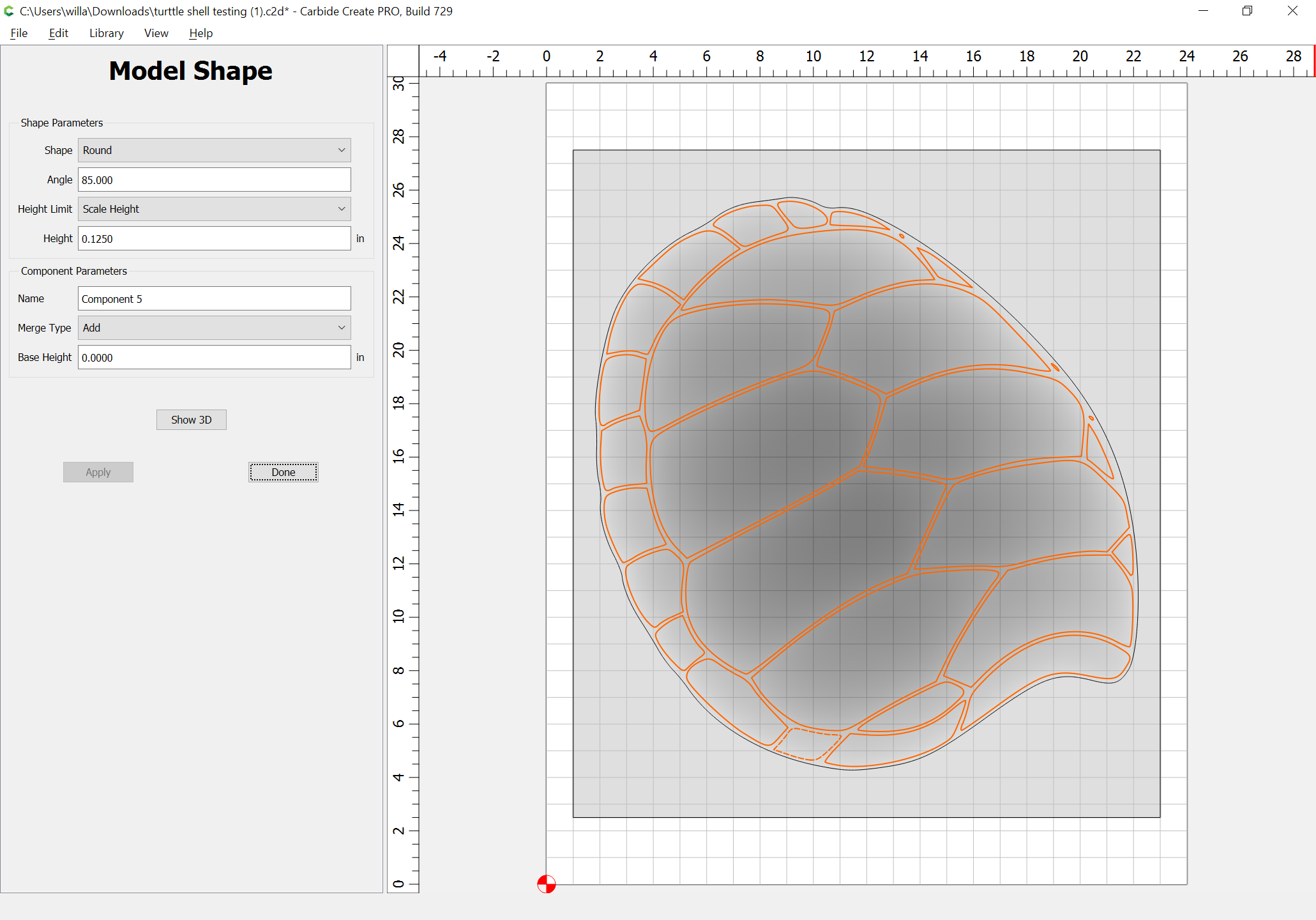
Is there some “instructions” that detail all the options for ROUND, FLAT, ANGLE. in the shape parameters selections? Seems like while they may seem self explanatory, they are not necessarily so.
What do the “heights limits” mean/do?
In the “merge type” selection, how do these work? ie. ADD or Sub from ??what?? Also what about MIN.MAX. Multiple (to what?), Equal. These seems to do different things at different times.so not very sure how to use them.
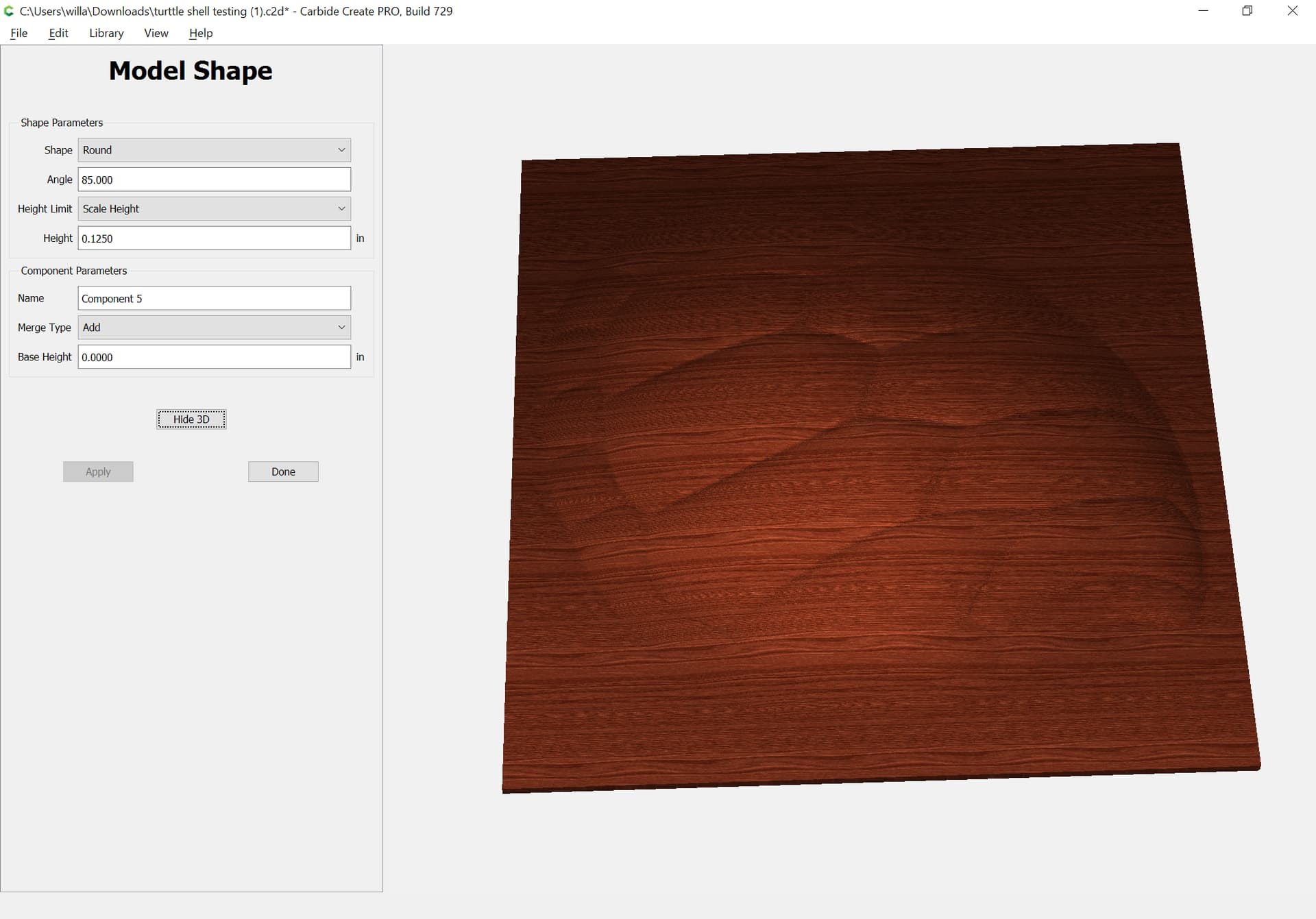
What does the “Base Height” mean…is this different than the thickness setting in the project setting area?
It would really be nice if there were some/more/better/??? tutorials on this area. I know there is a lot of power/capability in this, but is it all fly by the seat of your pants and try to learn?
Sorry to be so slow to learn, but I’m kind of a visual type and just playing with a lot of different settings can get very frustrating.
One other thing, once you try some setting in the MODEL SHAPE area, the EDIT doesn’t give you all the settings so you have to write them down separately, delete the component and start all over again.
Is there anyway that the EDIT of a component can have ALL the setting brought back for EDIT/REVIEW. Would make trial/error a lot easier.
Again, thanks for all your help. This is my first really big try at 3D so we will see how it goes.
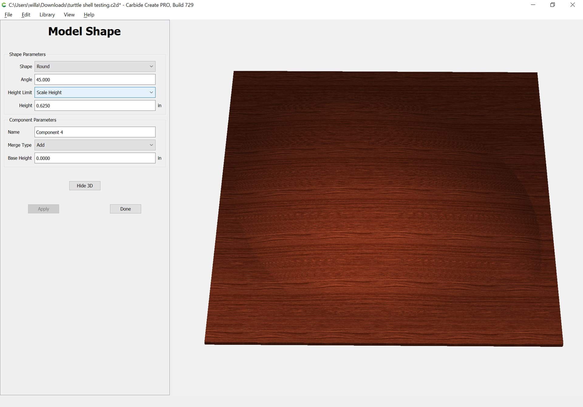
Limit/scaling height changes how it will be modeled elevation-wise
Adding/subtracting is done relative to all the previous 3D components. Min. or Max. bias towards the lowest modeled point or the highest.
Base height allows one to set a solid flat surface which the shape is then modeled from.
The tool is perfect for visual learning — draw a shape and model it, then change settings to see what ach does — except that once a shape is modeled one has to delete it and re-create it to access all the settings.
The link above has some additional tutorials.
If there’s something which you are trying to do which you are having difficulty doing, let us know the specifics and we will do our best to walk through it w/ you.
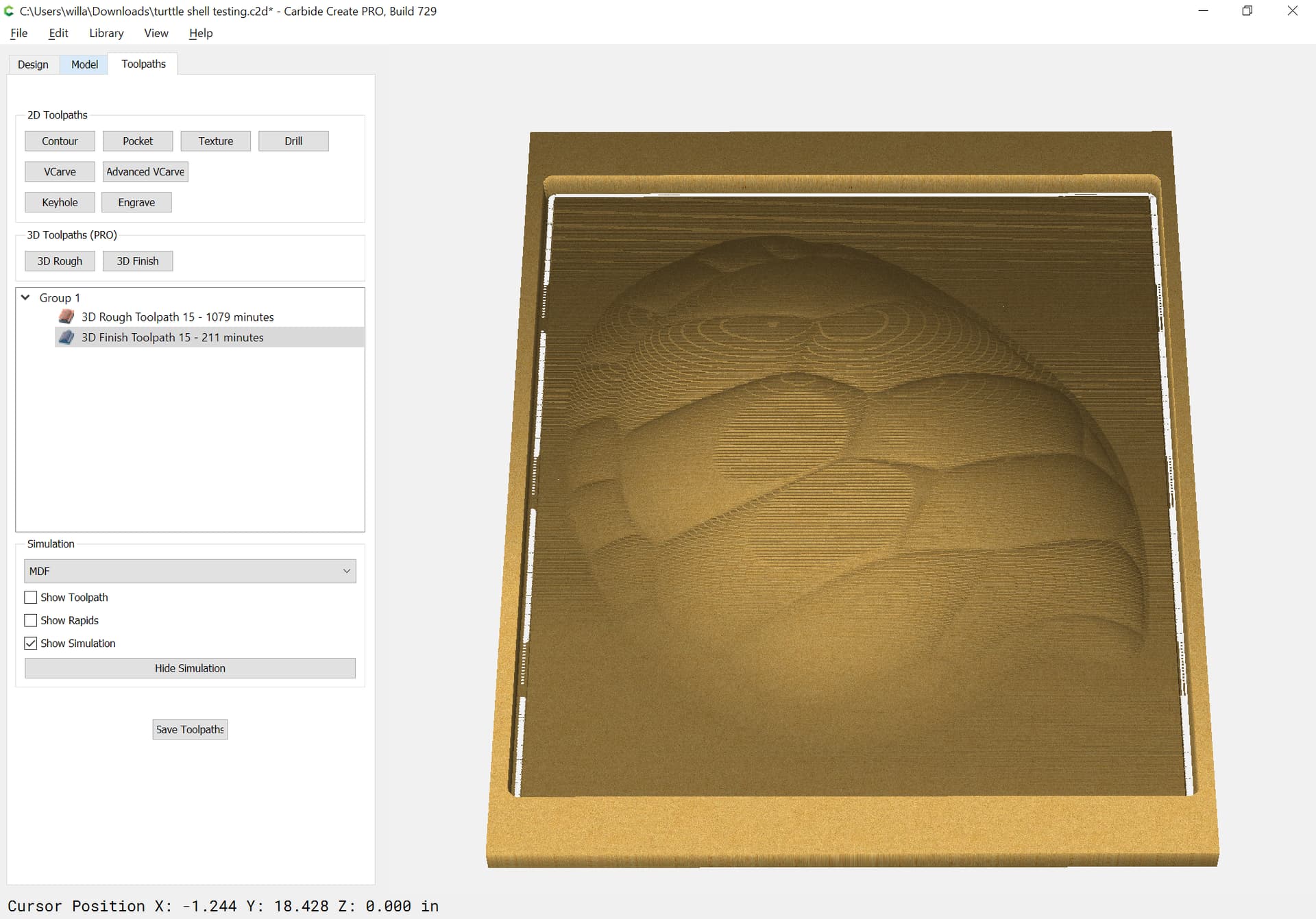
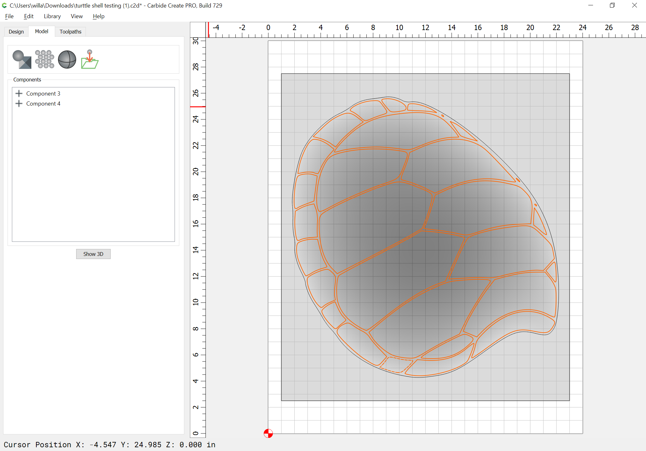
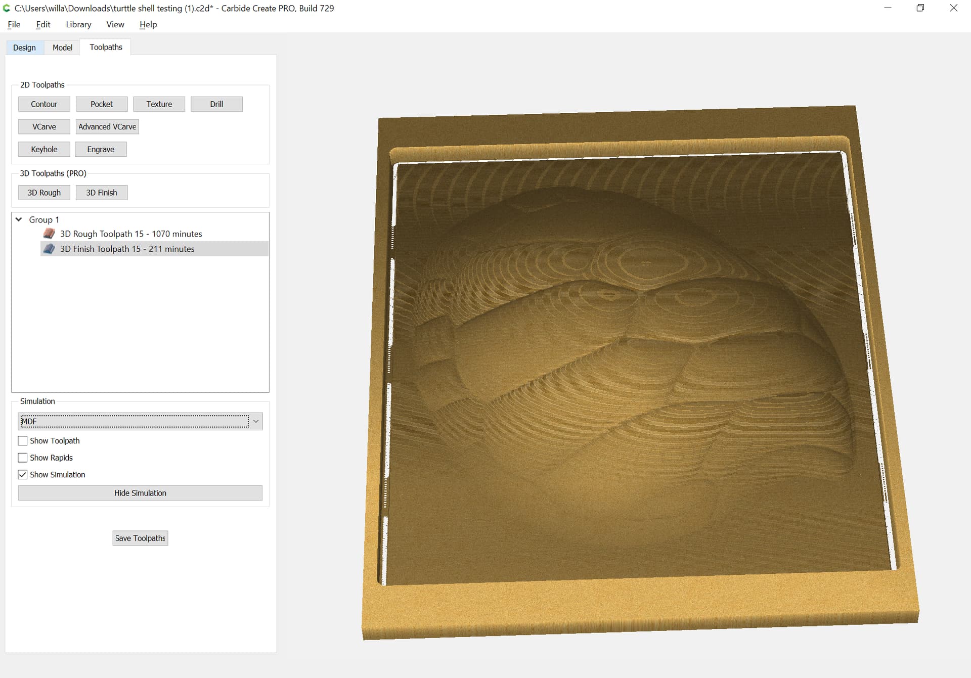
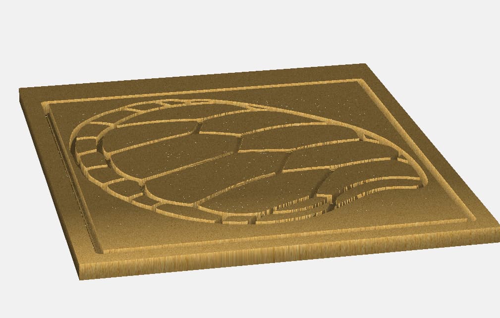
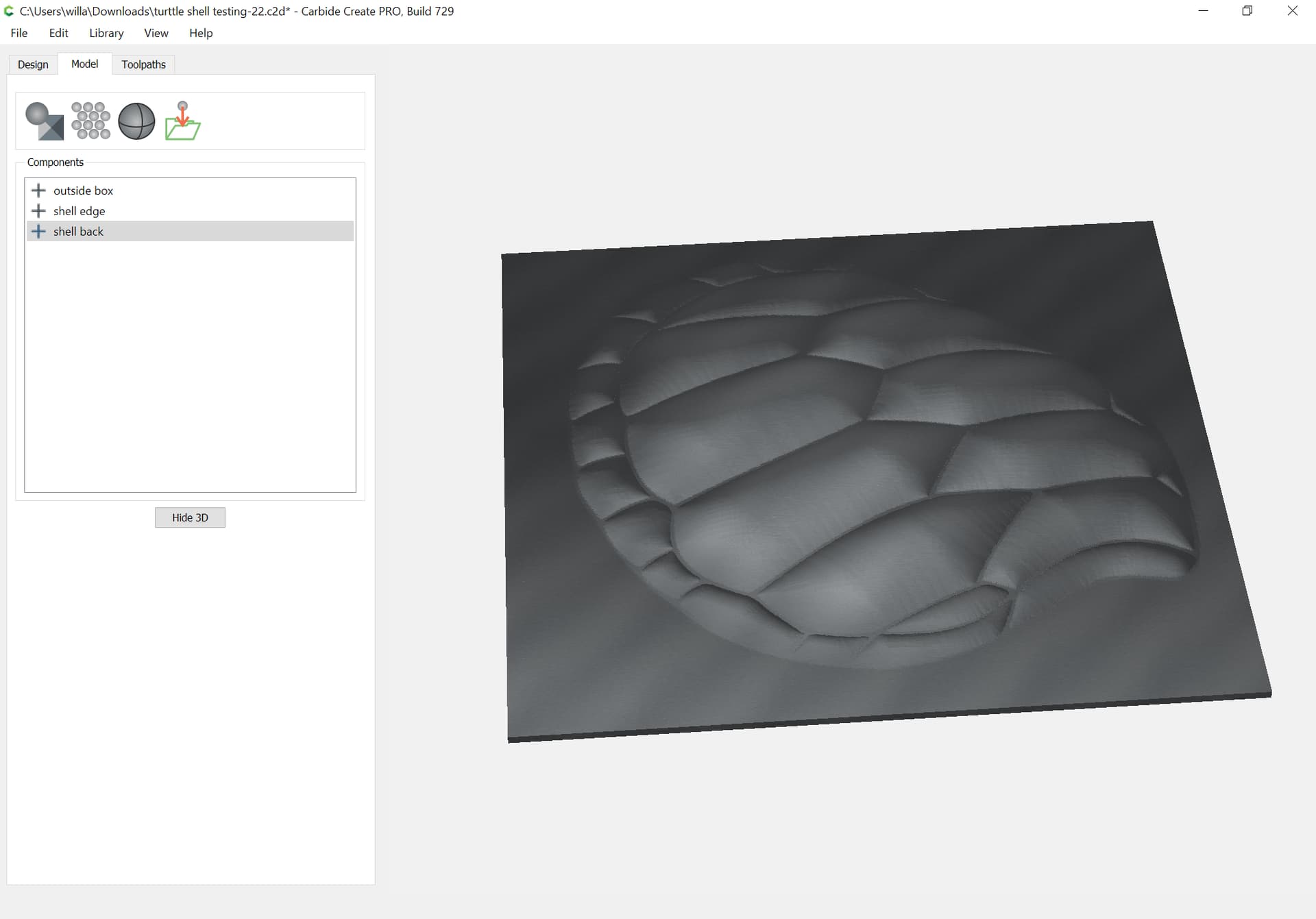
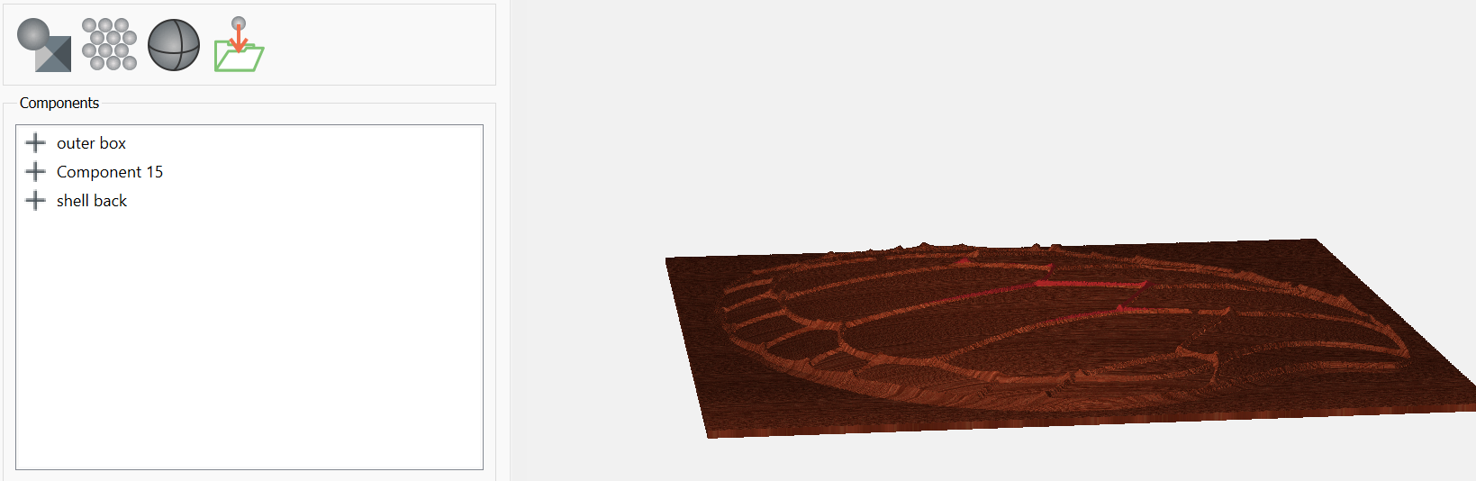
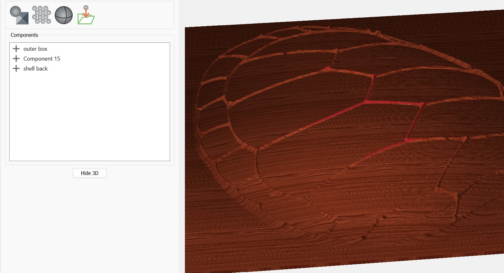
I have followed the info you laid out, three times now and I get the following. The “turtle back” should be as high as the thickness of the material (ie. 1.0- 0.25), but does not show up that way in the simulation. Instead it shows up almost flat, but does leave some kind of “sticks” standing up at various locations around the turtle back???
Obviously I’m still doing something wrong, but can’t seem to find out what.
Well, not sure what happened, but the file size has gone from the 664K size to almost 12MB and won’t load into this forum. No idea why it is so large now.
I used those exact settings. Of course, I can’t show them to you since the only way to get back to them, since they don’t show up in “edit”, is to delete the componet and start again. Which I have done three times now.
I guess since the file is now so big I can’t load it, I will have to start from scratch and try again.
Each of the second and third iterations of the design, I very slowly reviewed you screen and then ALT/TAB to my design to ensure that all was exactly the same.
What seems to be happening is that every time I delete and redo a component in the model area, the overall file size grows…like it is keeping everything even though it was deleted?? Does that make sense?
File size is now 12.5MB
I guess this just can’t be done.
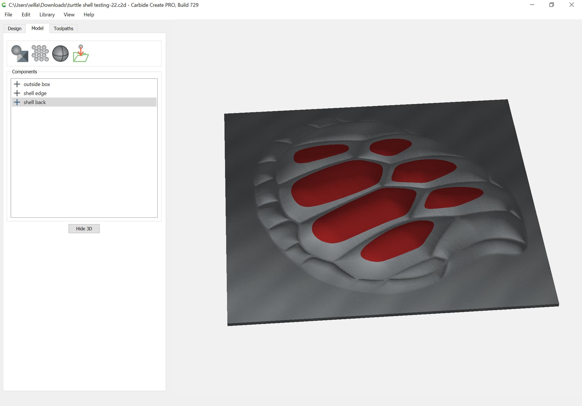
I started all over again, from scratch. Saved the file at each stage.
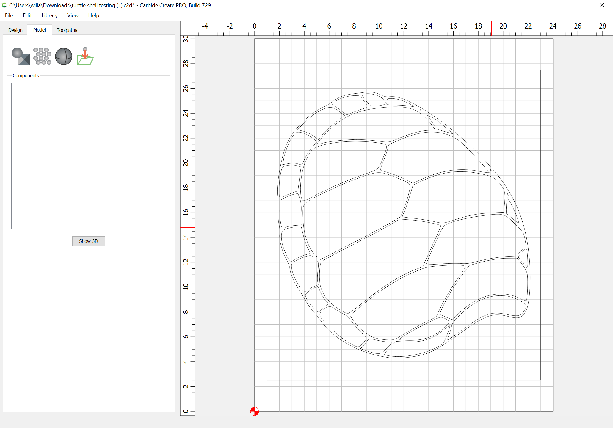
Stage one; just the imported svg file with the turtle back; 96KB
Stage two added box to outside; 98KB
Stage three resized turtle back; 102.4KB
Stage four added offset to box; 106KB
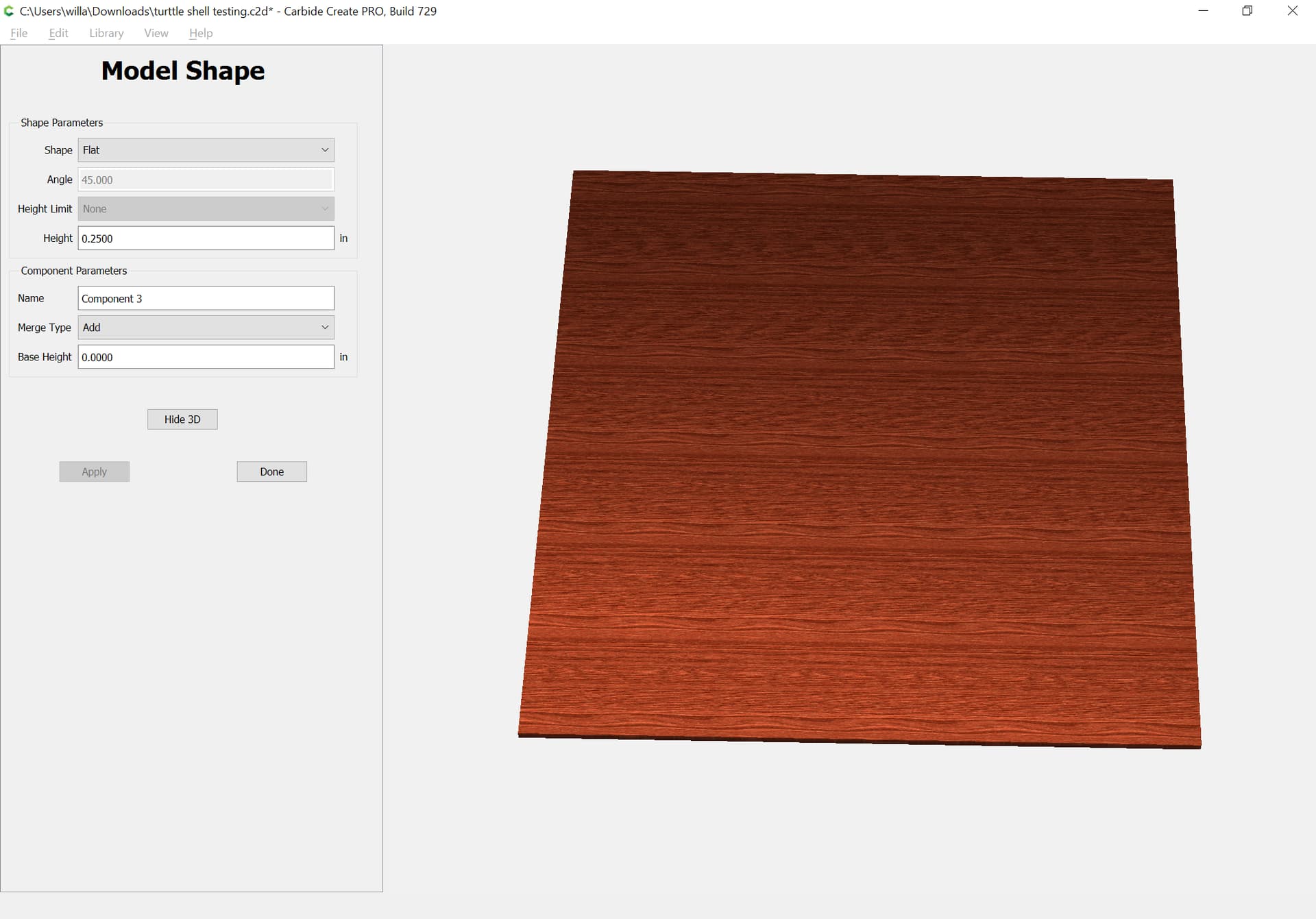
Stage five Model shape/outer box (flat;0.25;add); 106.5KB Stage six Model outer turtle shell only (round; 0.625/scaled) 6.5MB
Stage seven Model turtle shell back (round;80;scaled;0.125) 11.8MB
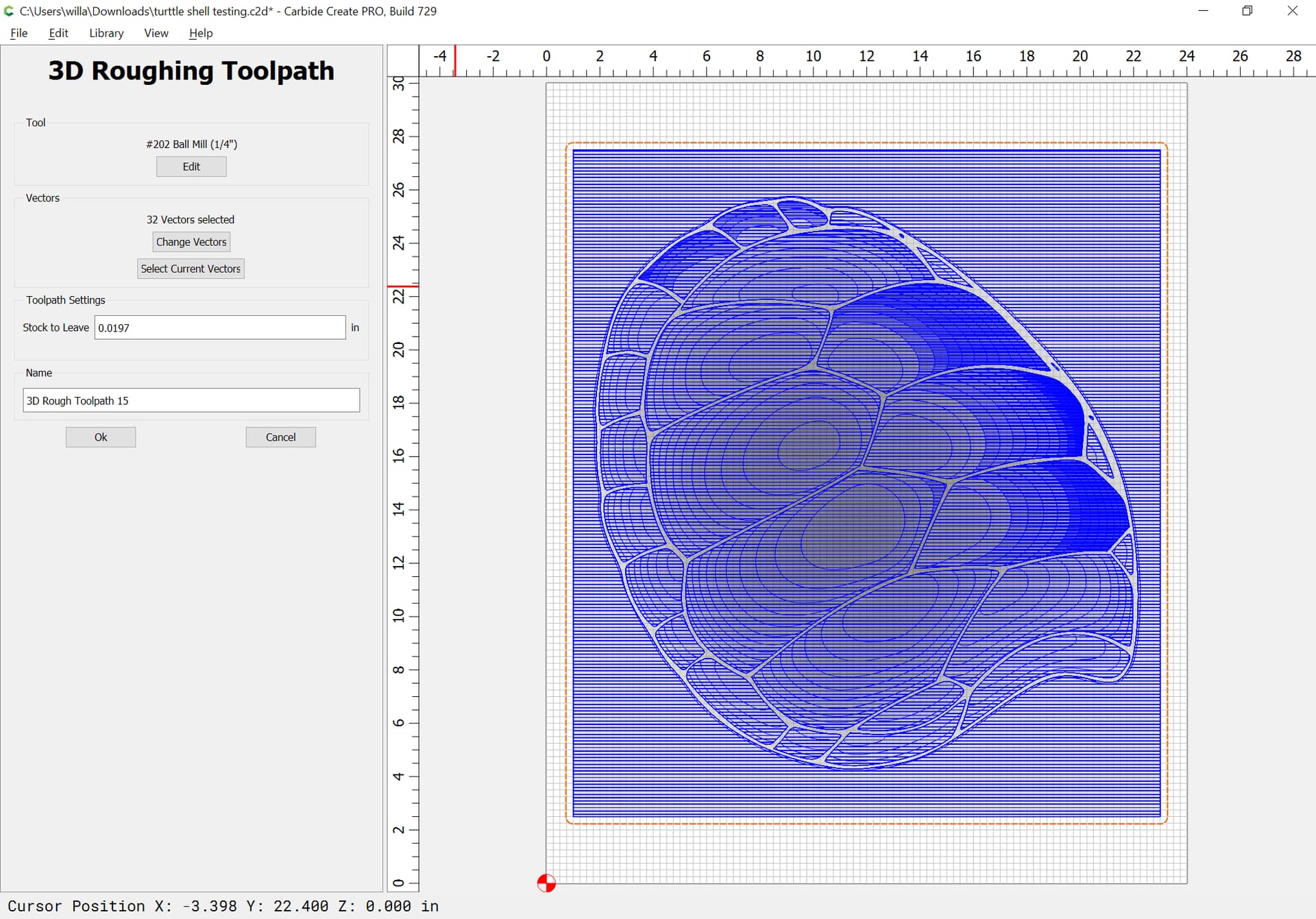
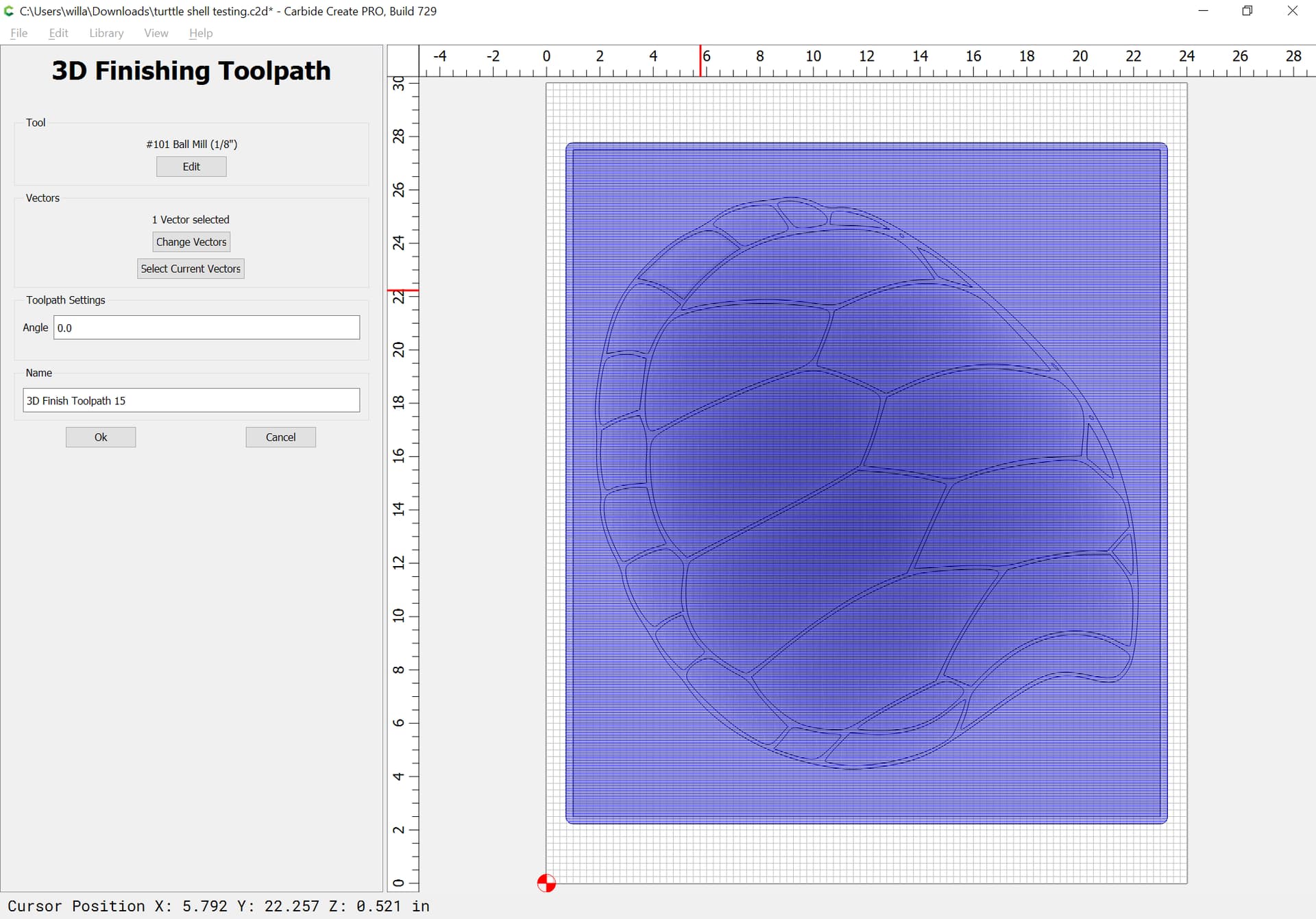
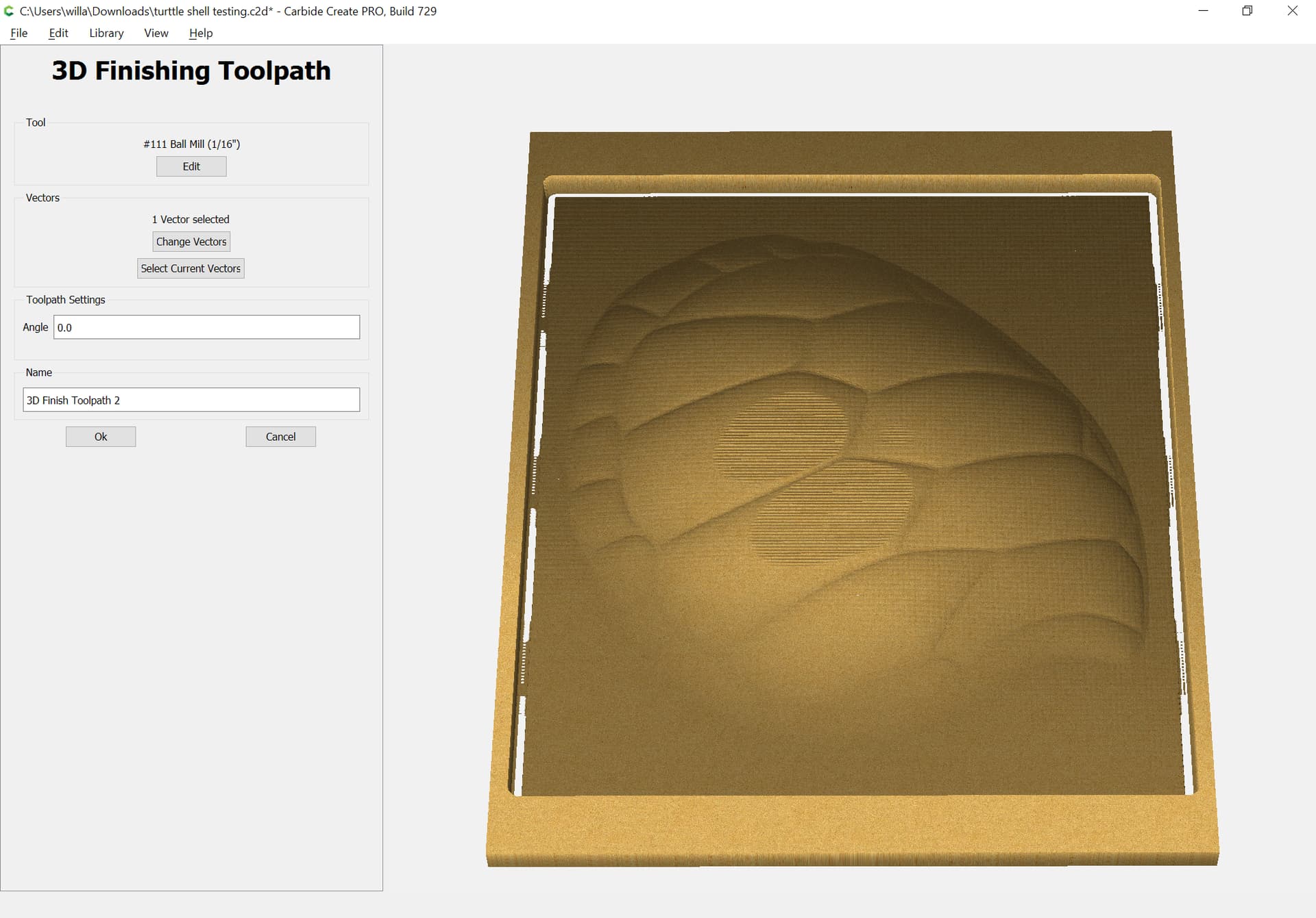
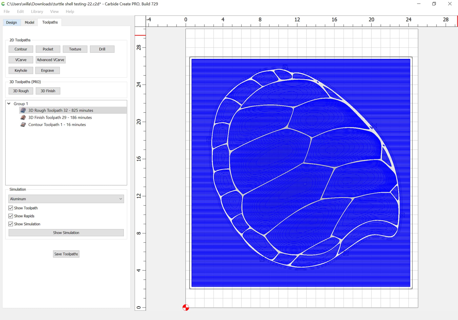
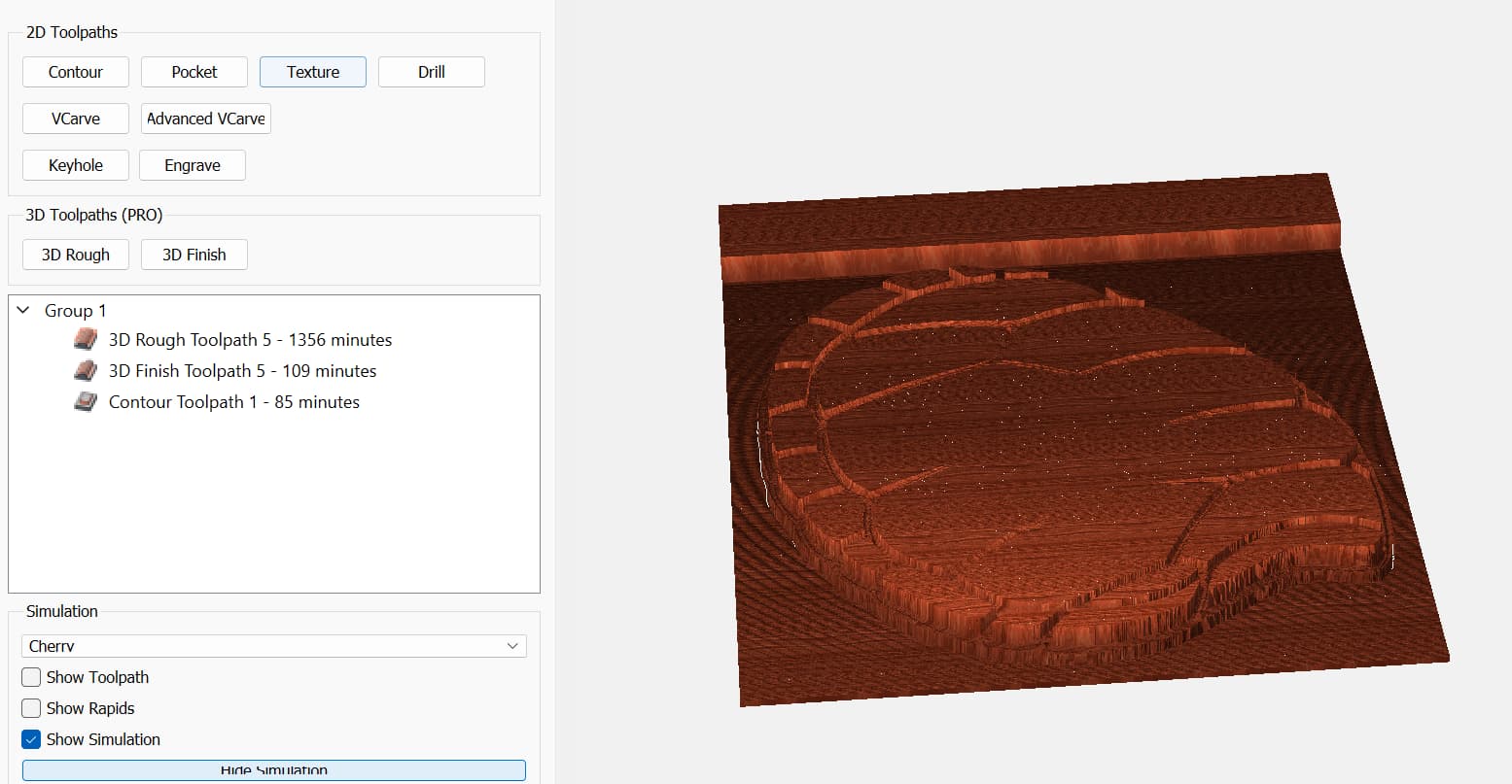
Stage eight: rough tooling with 1/4 ball and finish tooling with 1/8 ball;
File size 12.56MB
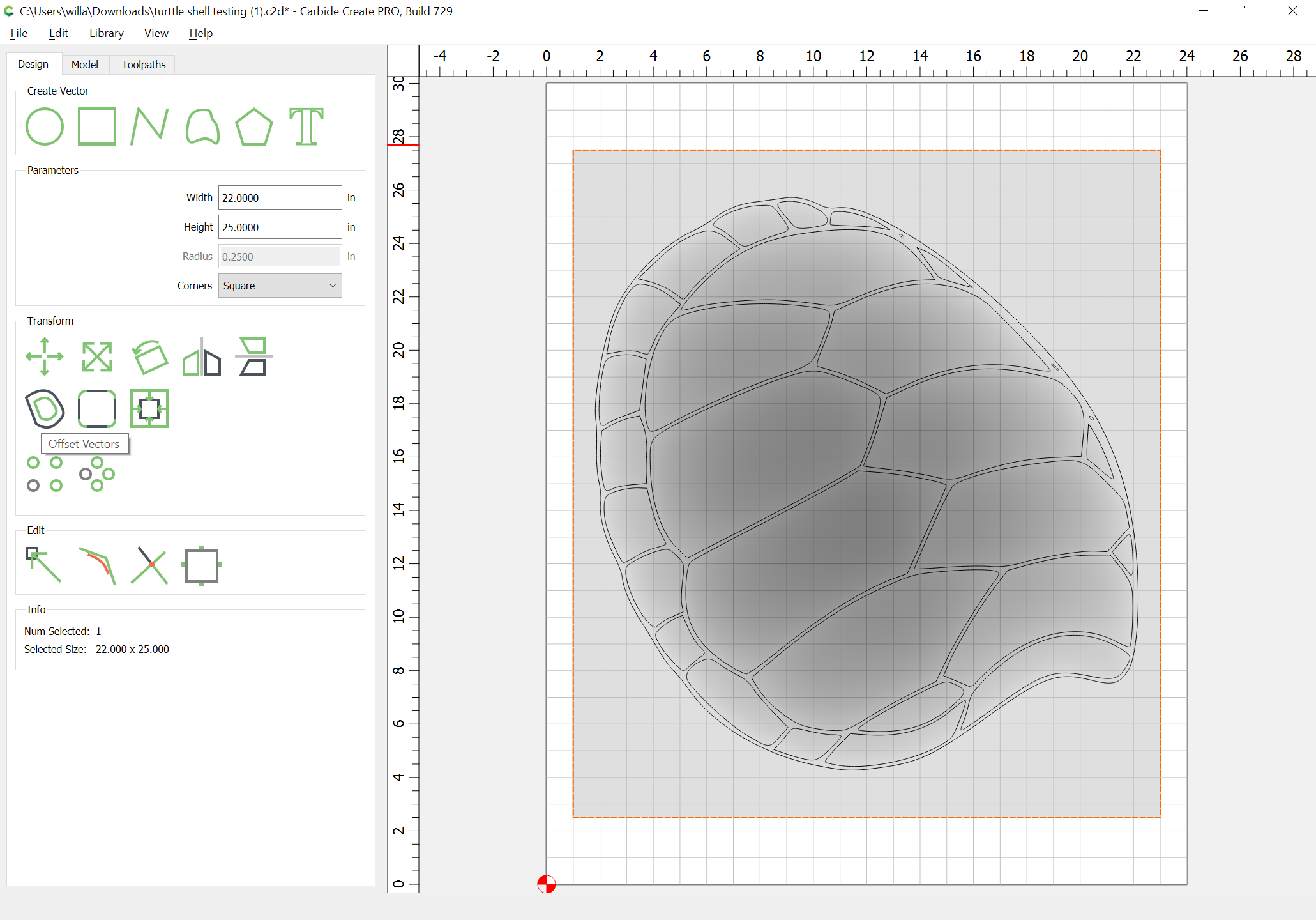
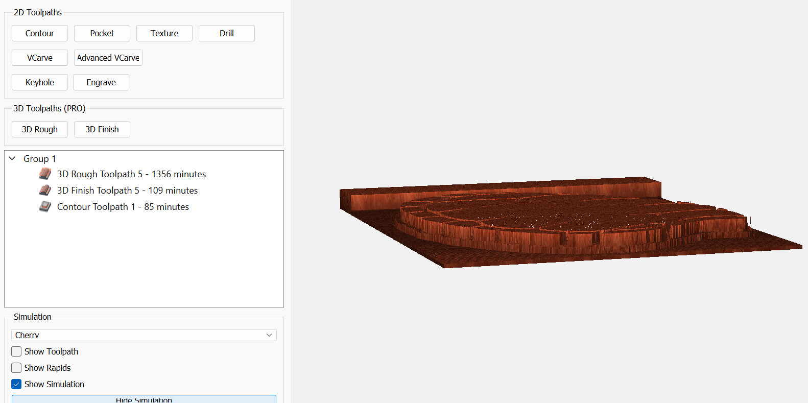
the Toolpaths will then be able to make something which looks like the design which you are making — if you select a region which allows the cutting to be done as it ought.
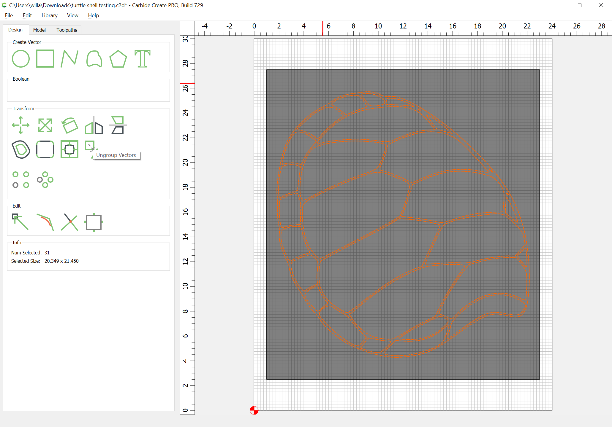
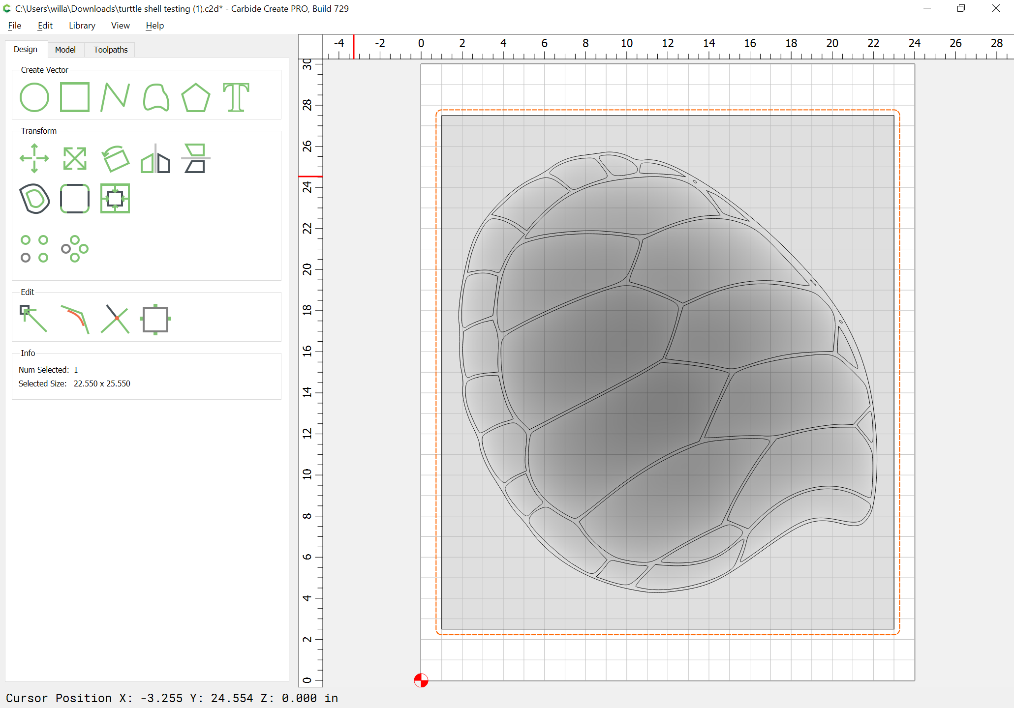
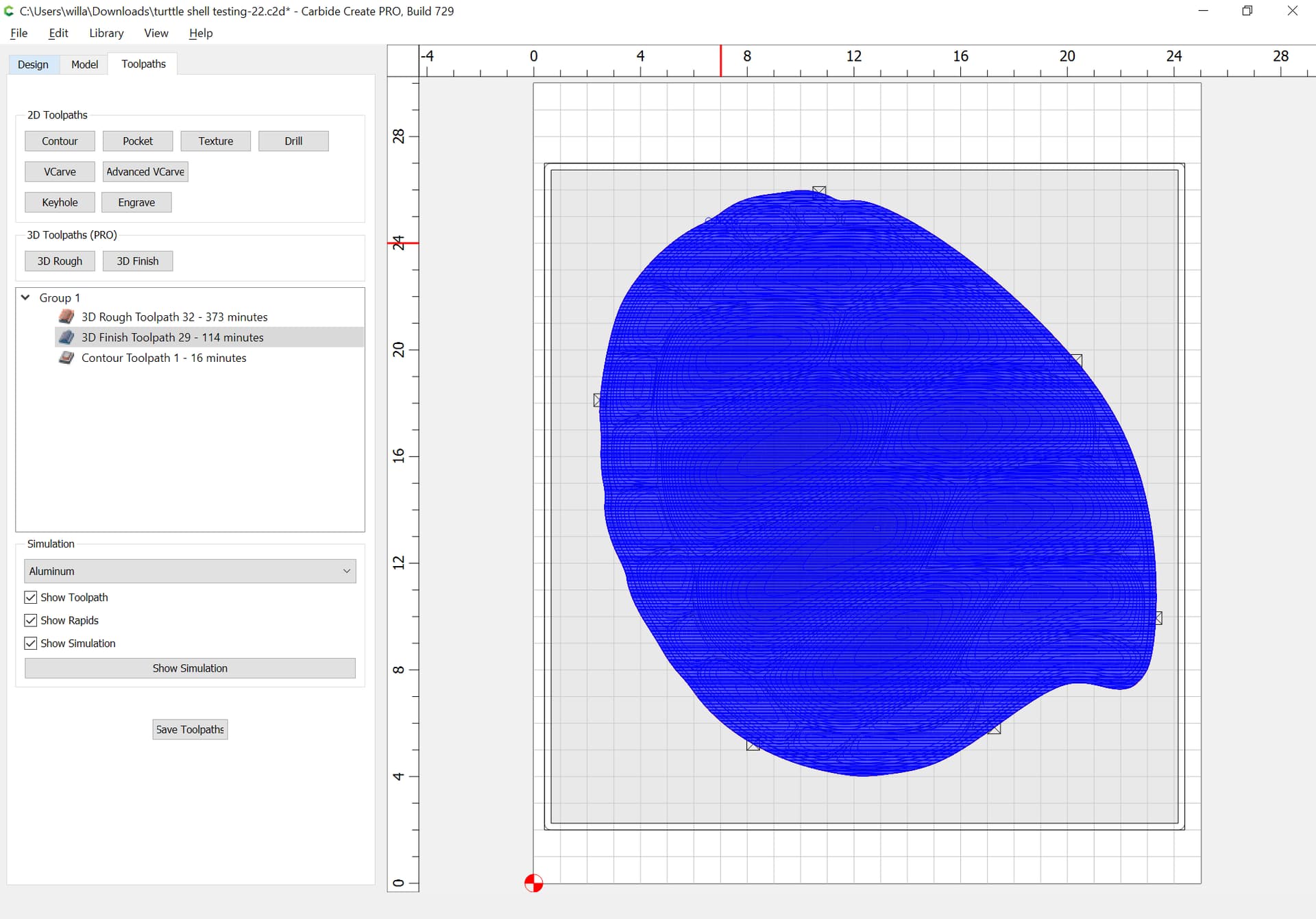
All geometry, except for the offset geometry which should be used for the 3D toolpath is selected:
Thanks for looking at it. Not sure why/how it got to deep/thick as I set the thickness in the setting, but will try again and see if I can use what you have suggested.