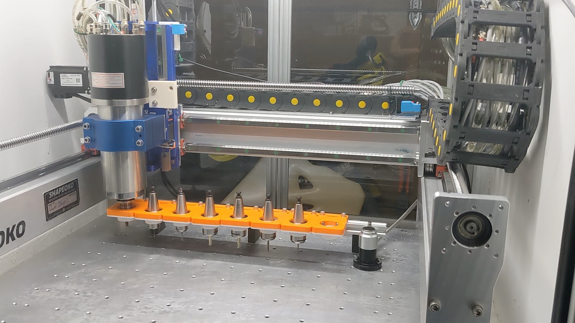
Been rethinking my HDM, replaced the controller, raised the voltage to 48v, added an ATC, designed a 12 tool retracting rack and a bunch of other things…
enjoy:

Been rethinking my HDM, replaced the controller, raised the voltage to 48v, added an ATC, designed a 12 tool retracting rack and a bunch of other things…
enjoy:
Welcome to the ATC club.
Quick question - all in what do you think you spent on the changes and how long did it take you?
I have a similar setup here.
For anyone looking to do something similar - step 1 is make sure you have en enclosure - I’ve seen the 40,000rpm version of this spindle fly out first hand.
I can appreciate the work that @davidgjohnson put into this, but I can’t help to think this is the wrong platform for such radical changes. The HDM is structurally a beast, I just feel like the use of GRBL is holding it back. I would absolutely love, love, love to be able to purchase a bare bones HDM with no electronics at all. Just utilizing the motion components and add on something like a MASSO with Clearpath Servos. I truly miss the ability to do 3D probing, and gcode rotation, and gantry squaring, and auto leveling, and… and…
I’ve also had a tool holder pull out once, it is a scary moment and the inertia even a small ISO20 holder has is crazy, and it wasn’t at full 30K RPMs.
I also would suggest closed steppers/servos when it comes to ATC, being able to trust that the machine knows where it is and in relation to the tool rack during a tool change is very important and can lend to more trusted “unattended”* operations. I have been saved a few times from the machine inflecting self-damage because of this as well.
*I still wouldn’t suggest leaving a CNC machine out of hearing/sight that doesn’t have all the industry safety compliance and features that a typical consumer grade/DIY CNC would lack.
Nice build @davidgjohnson, much more elegance and thought than I, when I went ATC ![]()
sorry, a bit confused…
what platform are you referring to? HDM, UCCNC, ??
Sounds like you didnt watch the vid, (I replaced everything on the HDM in the process)
thx,
IMO, length of time is a function of knowledge, bandwidth, priority, strategy, money and shipping… ![]() so I cant give you an objective timeframe. other than that, now that I have done it I could certainly kit it up with instructions to perform the work in several hours.
so I cant give you an objective timeframe. other than that, now that I have done it I could certainly kit it up with instructions to perform the work in several hours.
cost-wise, that is also subjective, there are all levels of quality across the entire part list, I chose middle of the road quality with verifiable product specs, I would have preferred higher end equipment but I have a fixed income for these projects.
id love to hear more around the specifics of your tool holder failure. whether the spindle had sensors, were leveraged through logical assertions in code and that the clamp procedure was consistent with the manufacturers guidance.
curious, I have a lot of questions…
Did your pull stud fail when the tool holder released?
Did you have clamp sensors in the spindle?
Did your M6 logic incorporate logic assertions to ensure the clamp was in the right position?
Did your M6 logic properly apply clamp pressure (after the tool release) they seem to have very specific timings to ensure clamp is fully engaged.
maybe servos or closed loop upgrades at some point. (more $$$)
hand always on the e-stop these days… have to build trust in the setup (100%)
ty
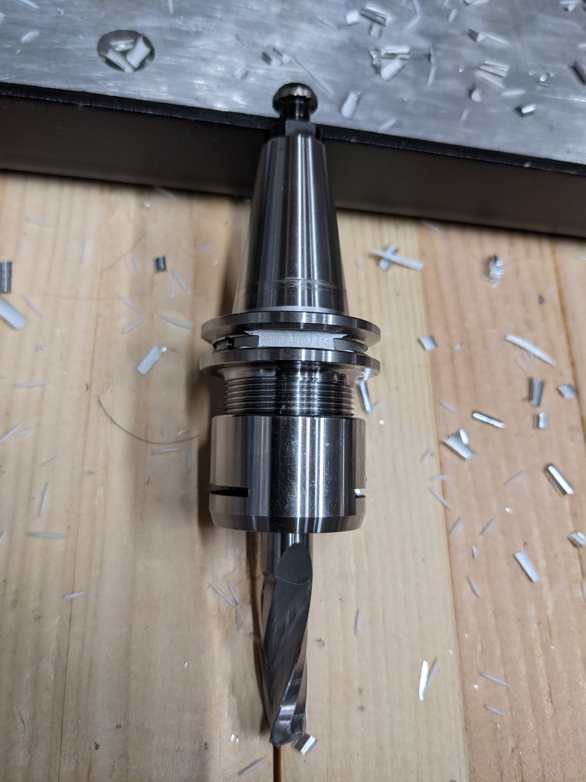
It was first days of the spindle being operational, no tool automation at this point just manual quick tool changes. It was more human error than anything, a miscalculation of cut depth and feed rate. Cutting forces and probably mostly the leverage causing it to pull out.
3/8" single flute suffered broken/chipped tip and tool holder has imperfections on taper and pull stud is “rounded”
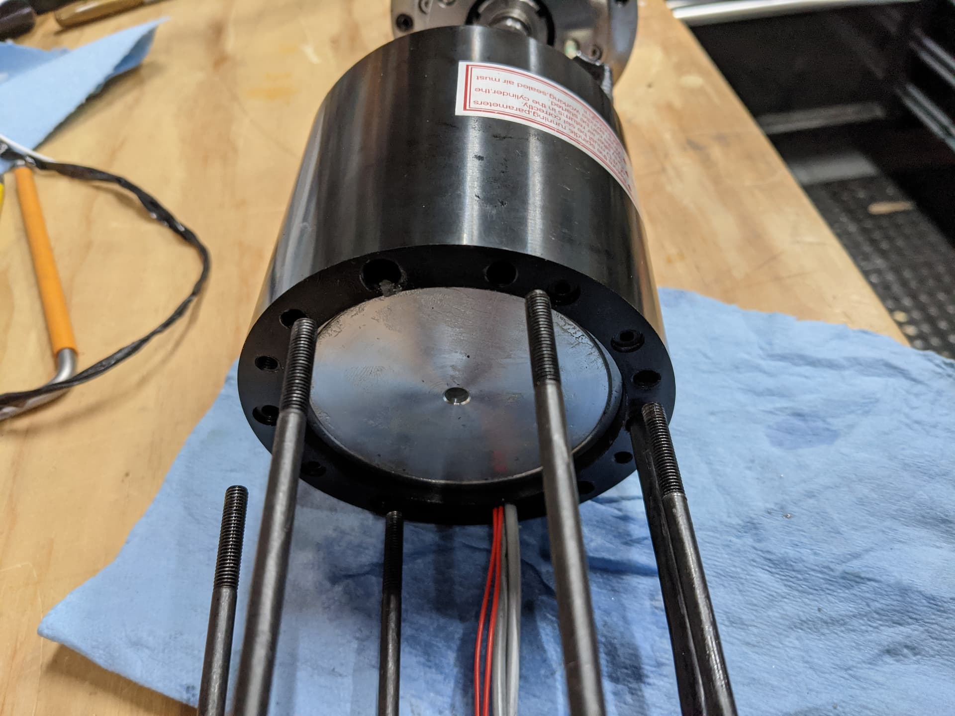
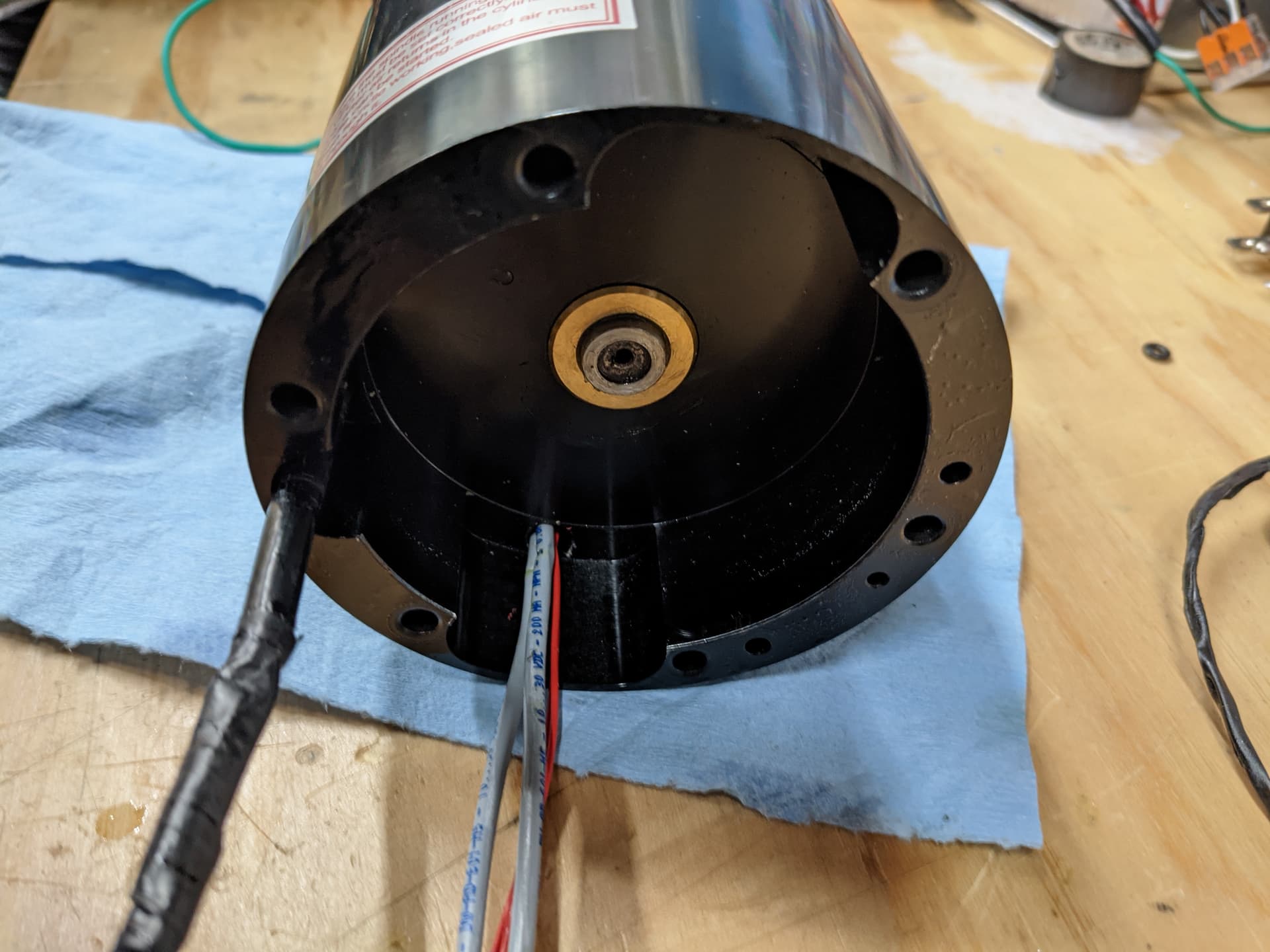
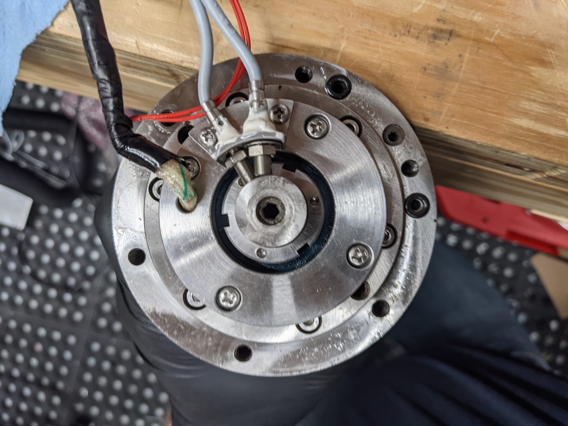
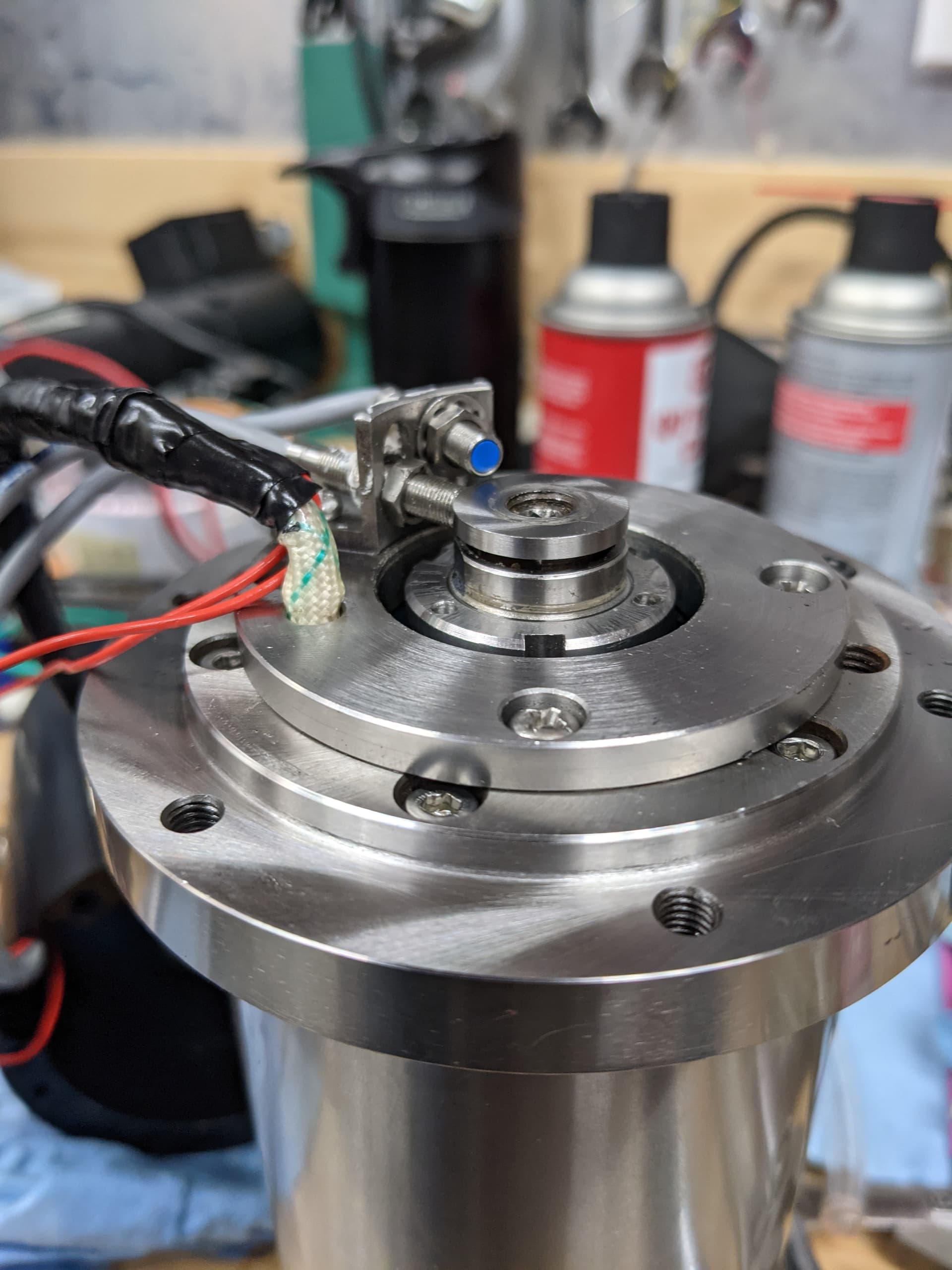
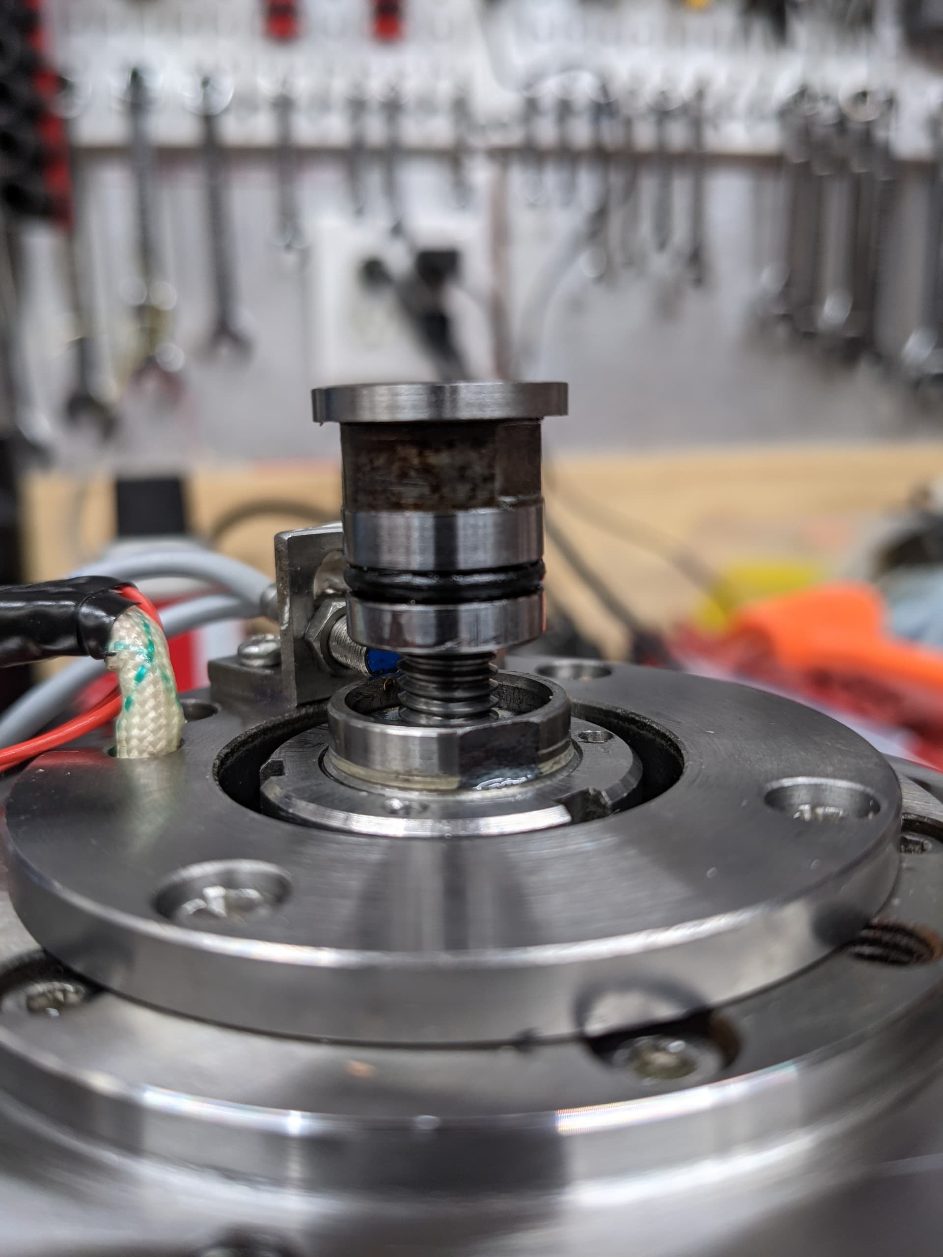
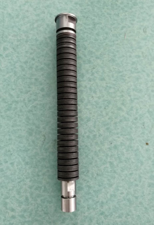
Clamp pressure only retracts the piston, the drawbar has spring washers to retain clamping force. You can actually relieve air pressure afterwards if you really wanted. Here are some glory shoots of the spindle top and piston when I was inspecting everything.
I finished up the video and had a laugh, I was gonna ask about your M6 macro but I know it extensively ![]() , you happen to use my M31 as well? Let me know if you have any suggestions, issues, etc.
, you happen to use my M31 as well? Let me know if you have any suggestions, issues, etc. ![]()
You mentioned Fusion Probing, I actually have been working on supporting Fusion’s WCS probing, but not necessarily the inspection piece (behind the $$$ manufacture extension). I am hoping to work on it more this winter. I decided on creating my own probe routine macro that models similar to Renishaw’s, which includes updating WCS, tolerance assertions, tool wear and dimension report files. These are WIP but can be seen under the fusion360-probing branch on my repo (PP, M32).
I would watch every in depth video you create about this setup because I want to learn everything possible about the process.
I am good at following wiring diagrams and have done a few air suspension setups on mini trucks so the air solenoid valves and air line pluming are not a problem for me. Programming and setting up the software to accommodate all the inputs and out puts for the CnC controller to run the relays and sensor controls and stepper drivers is where I need educating. I’ve never added, modified, or written my own script for anything outside of a school play.
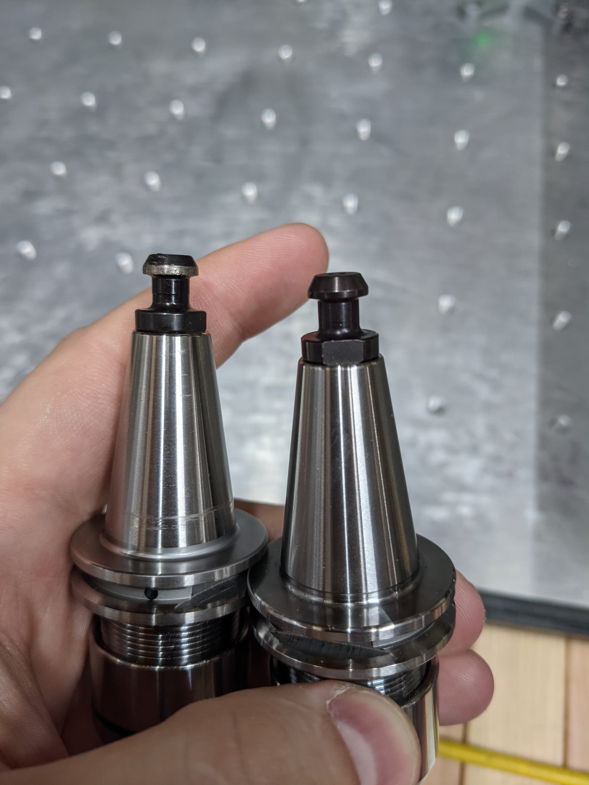
the pull stud cap on the left looks to have a thinner cap.
while the clamp assembly is spring loaded, my spindle has a clamp input which is used during tool change (5seconds) to fully seat the tool clamp.
in terms of the M6 macro someone shared it with me, wasn’t sure of the source. (now I know)
but I did have to add a bunch of logic to clean up the pneumatic support and pre/post calls) I may have had an older version…
I have a working fusion360 post processor with WCS probing, geometry and Inspection working.
(although inspection relies on UCCNC M40/M41 digitizing)
I have not implemented wear yet, I am finishing up multi-axis on the inspection features as fusion allows you to probe at angles. happy to share with you if you’re interested.
I think thats just because the tool holders aren’t at the same angle/plane in the photo. While it was damaged at the point, I checked the pull studs and tapers on all my holders to make sure they matched. At least with my limited amateur “metrology capabilities”.
I hadn’t incorporated a sliding rack, it hasn’t been requested ![]() but I personally use a drop-in rack.
but I personally use a drop-in rack.
I did add some workflow changes/prompts and fork side-loading through people’s requests.
I can merge in your additions if you like (making them optionally configurable). I liked the idea of the probe prompt to connect it before continuing that I saw in the video ![]()
I’d be interested in how you went about your solution, sounded like you went more PP and [native] GCode on the (WCS) probe routines?
You plan on hacking the “angle probing”, due to it still a feature request? I’ve only seen Probe’it do it via safe probe jog tripping.
I’d also be interesting in hearing about your use cases and workflow for WCS and inspection probing, sounds like that might be a future video. +1
And there I was thinking I was the only one who had taken apart one (four) of these…
I watched. I just wish we could get the HDM as a bare bones machine and BYO electronics. This platform with better electronics would b ideal.
This topic was automatically closed 30 days after the last reply. New replies are no longer allowed.