I’m sure it comes as no surprise, we looked at a number of ways to ensure chips stay out of the Y channels - I’d have loved bellows but the compression length left allot to be desired and we’d have lost around 150mm of travel.
You really have to cut hard, fast and allot of material to fill up the channel between the side covers - enough to cause any kind of issue. The chips also have to be really big to get enough momentum to get in there on mass - the side covers do good work for their simplicity.
I fear that this is a testing issue, I suspect that Luke’s copy of Carbide Motion has only
“Reset Feedrate”
and
“Feedrate +10%”
The
“Full Send”
and
“Do it for Dale!”
buttons must be missing…
In the machine’s defense, Matt is probably approaching material removal rates that rival most small mills (Tormachs). We need to get some video…for science @TheWatchMker !
I don’t have an HDM, nor am I that familiar with the design. But I have an old German Ballscrew machine that uses what I think is a pretty simple solution, seems to work quite well. The Z and X bearings, rails, and ball screws are not visible, they are enclosed. The external portions pass through rubber like teflon strips. Boat tails are machined onto the leading edge of carriage pass throughs to facilitate gradual and smooth opening of the strips. The y screws and bearings are mounted in typical configuration below the plane of work surface. Anyway, seems like something that could be adapted to a machine like the HDM.
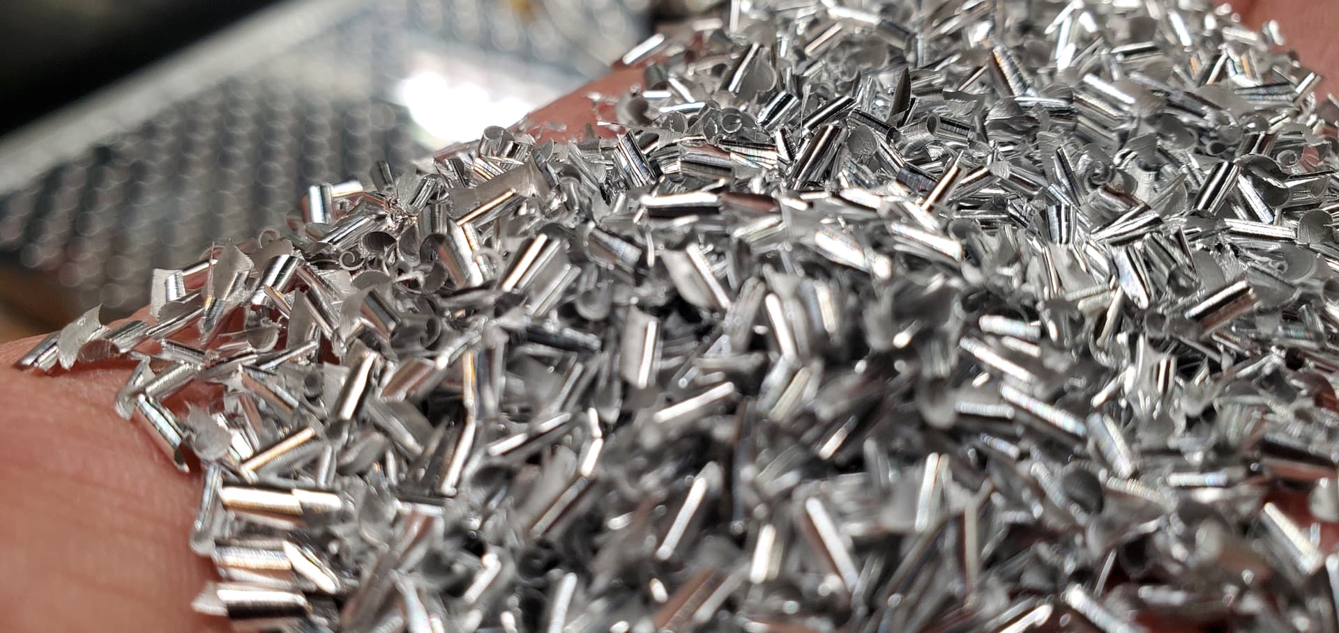
How much stock are you leaving with those TAS roughers? The chip pile size difference is huge when using chip breakers compared to traditional mills when running at full depth and really makes smaller dust collection systems go much longer before having to empty them.
totally been slacking on these.
Got so much else going on and ive been vacuuming and blowing out inside my rails every run and sometimes a few times during longer runs and hasnt been a problem since.
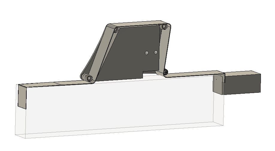
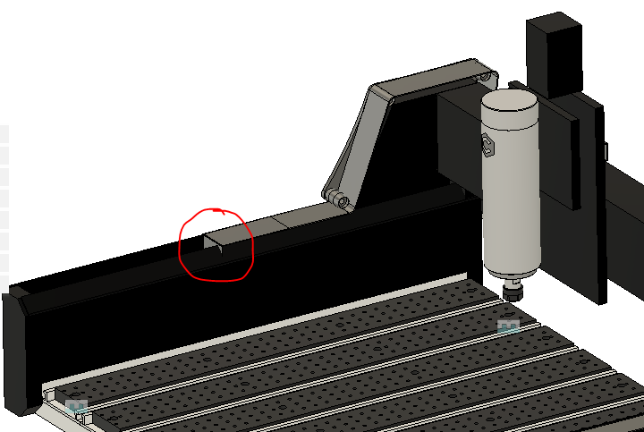
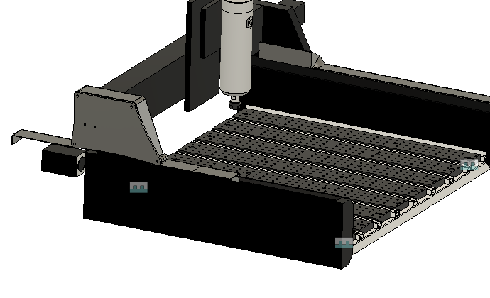
this is my concept if anyone else wants to run with it. the belt has rollers to go up and around the x axis, its fastened using the bolts in the front and the rear. The rollers are mounted to the side of the x gantry supports.
Im sure i could make it alittle better with some flushing out. i just dont want to slow down anyone who needs it.
in the mock up with the circle it would extend to the front.
Mount a couple steel plates to the end plates and use focus magnets for easy mounting with a door sweep brush bent at a 45 degree angle in front of the bottom belt roller on the gantry plates to sweep any chips off the belt back into the bed area.
Notice the “Min. Pulley Diameter” on those belts?? Not sure if that indicates how flexible the belt is.??
Also, wouldn’t the 2 exposed rollers allow for chips between the rollers & belt?
I love the idea of a continuous belt. Doesn’t limit range of motion at all, and isn’t obtrusive.