Perfect.
Here is a file.Formations Test 2.c2d (45.2 KB)
Thank you.
Perfect.
Here is a file.Formations Test 2.c2d (45.2 KB)
Thank you.
Here’s a first set of questions for you:
can you confirm which toolpath in the file corresponds to that video ? I’m a bit confused because the only enabled toolpath uses a 1/8" square endmill at 4ipm / 0.3ipm plunge (which is what you mentioned in your post above), while there are other toolpaths using a #202 ball endmill, which is closest to your 1/4" diamond grit ball cutter, but feeds and speeds are different for those?
can you also confirm which RPM you had your router set to during the cut?
do you have a link to that diamong grit cutter that I could check to know more about this tool?
Reading a bit about machining concrete, it sounds like doing it with a Shapeoko (and a stock one at that) is going to be very challenging anyway (because people apparently normally use very rigid machines to do it), so don’t expect too much (this is a fun experiment, but the answer may well be that one has to reduce load/depth of cut so much that the resulting cutting time is not acceptable…we’ll see!)
In response to you questions:
I did a lot of investigation regarding the engraving of stone and concrete. While I do not know a lot about engraving of concrete I run a concrete sawing and drilling construction company. So in the investigation I looked at other machines, visited tradeshows before deciding on the Shapeoko. In my opinion, it is the best option for the portablity factor.
The only other machine that I thought about is from this company https://redarttechnologies.com/, but I was thoroughly unimpressed with the machine and the owner.
Thanks for clarifying that, this was for me to establish a baseline (your current cutting parameters) and compare it to an adaptive-based alternative.
So your baseline is:
If I use that in CC on your sample vector, I get 3.5h cutting time for those three letters:
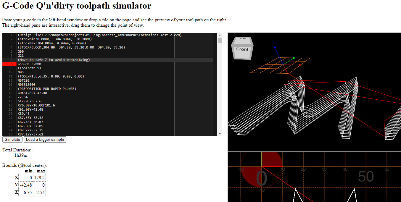
but then again the generated G-code previewed in a different tool tells me it’s going to be 1.5h:
Which one seems to best match the cutting time you are seeing ?
In the meantime, I stumbled upon this cool page:
And that is telling me that my “deep adaptive toolpath” approach could actually make sense, because that guy is doing exactly what I was about to do in Fusion360: ramping down at a very low angle, and once reaching the full cut depth, start moving in circles at a very small stepover (basically adaptive clearing). He also uses feeds and speeds that I would have aimed for (60ipm ballpark), so there’s hope.
Soooo, give me some more time to do sam CAM in Fusion360 tonight, and check cutting time, and then we can get down to milling tests!
![]()
Let’s prove that there’s nothing a Shapeoko can’t do !
EDIT: did you get some of those on that Amazon special ?
It should allow to cut deeper that the ball one
btw Carbide Create makes toolpaths that have different forces during it’s path…
but you can “smooth this out” using a tool:
https://fenrus75.github.io/FenrusCNCtools/javascript/gcode2gcode.html
that adjusts speeds to have a more equal forces across the paths
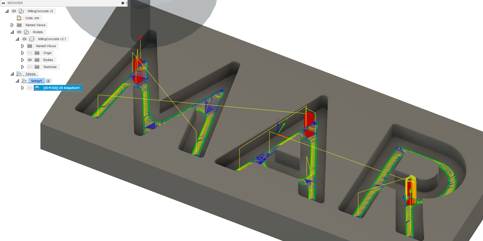
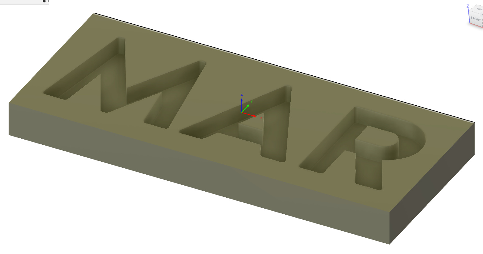
@isoworks: so an adaptive toolpath will look like this:
zooming in :
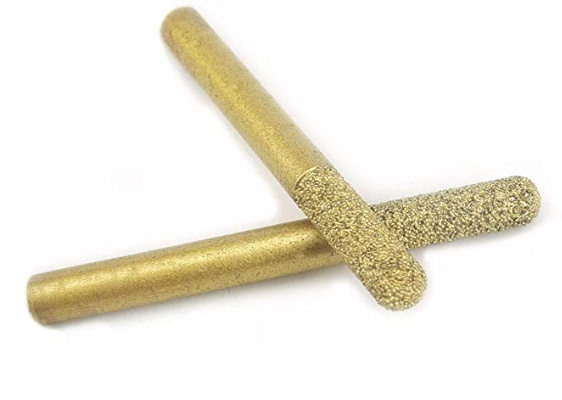
However this assumes the use of that other tool in the picture, that is only rounded at the tip, to be able to cut 0.25" deep in one pass. The ball tool is 1/4" in diameter, so it cannot take more than 1/8" in depth and you woud need two passes:
=> let me know which one you have and want to use, I’ll adjust the toolpath and post a first G-code test file !
Julien,
That is fantastic. Let’s use the ball end mill with the straight sides, not the in-cut.
I agree with the smaller stepover on the first attempt.
A couple of notes about why concrete is even more difficult than stone.
Most stone is relatively homogenous and therefore it is simpler to set up parameters for that type of stone.
Concrete has a very difficult mixture of softer abrasive particles of sand and cement. This is mixed with much harder aggregate. Sometimes, as is the case with the concrete in this mix, the aggregate is river rock and therefore smooth and round.
The abrasive particles will eat the electroplated coating and the hard, round aggregate will cause deflection of the cutting tool.
The combination of factors is the most devastating combination. This is true for large, heavy-duty concrete cutting machines and even more so for a small ball end mill.
It will be very interesting to see how the adaptive tool path will behave.
And you are correct, the tool is 6 shaft but the OD over the diamonds is .25".
Allright, so first the obligatory “use at your own risk” disclaimer:
That said, here’s the G-code file:
MAR_AdaptiveTest_0.004stepover.nc (2.9 MB)
In case you want to install Fusion360 and take a look, here is the project file:
https://a360.co/30re4JE
to match the rest of Christian’s settings, I suggest you set your router to 25000 RPM, that’s 4 on the dial. The higher the better (but the router screams at 30.000RPM, so 25k is probably good enough)
the settings are what I described above: 30ipm helical plunge at 1° angle, followed by adaptive clearing at 60ipm and 0.004" stepover and full 0.25" depth.
Fingers crossed, I’m curious to see the results!
EDIT: I forgot to add, that you may want to run the G-code file as an air cut first, to check that there is no obvious issue/surprise, at least for the first few seconds.
Julien - I will run this tomorrow. I will let you know as soon as I have some results.
Julien.
That went remarkably well. Here are some videos and pics.
I would like to increase the overstep and run it again. The initial suggestion was .020 and it was run at .004. So let’s try .012 as the new step over.
The one minor issue is that it seemed to spall the edges just a bit more.
So now the decision is whether to move to Fusion 360. I am worried about your comment that it has a steep learning curve. CUrious about input on this from people who have made the switch.
Really impressive work! I recently made the switch to fusion 360. I started using carbide create and Vectric software for CAM earlier this year but I was finding it limiting in a lot of the same ways you seem to be. I can say there’s a lot to it at first so it is a little daunting but I went through all of the Fusion 360 CAM tutorials on the NYCCNC website and its all been much easier since then. I really love Fusion 360 now and most of my other CAD/CAM software has gone unused (Besides Vectric Vcarve since its so quick and easy for simple stuff).
P.S. I’ve also tried EstlCAM but find the lack of a preview option to be too nerve wracking. The fusion 360 preview is top notch and really helps to catch small mistakes before breaking stuff.
Glad to hear it worked out fine!
Here’s the same example file regenerated with a 0.012" stepover
MAR_AdaptiveTest_0.012stepover.nc (1.1 MB)
If this works, we may want to try a slightly lower feedrate and check whether that reduces the spalling
EDIT: here’s the toolpath at various other stepovers for you to try.
0.2mm / 0.008"
MAR_AdaptiveTest_0.008stepover.nc (1.6 MB)
0.4mm / 0.016"
MAR_AdaptiveTest_0.016stepover.nc (904.0 KB)
0.5mm / 0.02"
MAR_AdaptiveTest_0.020stepover.nc (742.8 KB)
About the chipped edges, what we could try is running a first shallow & slow regular toolpath (as you did initially), and then follow up with the adaptive clearing. Another approach which is typical when using adaptive, is to use some “stock to leave” in the adaptive clearning toolpath (which I have set to 0 in the examples above), and then follow up with a contour pass on all walls to shave off the remaining material (slower but at full depth).
Oh and about Fusion360,
Julien - I will be headed to the shop late this morning to see how new tools paths go.
I saw that you posted the 0.0.12 stepover path and was going to ask you now for the other files. But you anticipated that question. So thank you for the .016 and .020 stepover files.
Thank you for the additional feedback on Fusion360. It does sound worth it.
Hmmm. I didn’t know that Fusion360 was a CAD/CAM platform.
I have a OnShape license so I am not inclined to get into another CAD program. OnShape has a number of CAM plugins. On first glance VisualCAM appears to the first choice, though not free.
So more research required.
I’m not familiar at all with Onshape, it does seem like VisualCAM implements “high speed machining” (so likely adaptive toolpaths). Another option could be to do the CAD in Onshape and the CAM in Fusion360 but of course that would be a less convenient workflow.
Julien - here is the update.
Concrete is such a difficult material to work with being non-homogenous.
Overall the the adaptive toolpaths are much faster. So we are absolutely on the right path. Here is a video of the 0.020" stepover. https://youtu.be/6DB4Zf2K1do
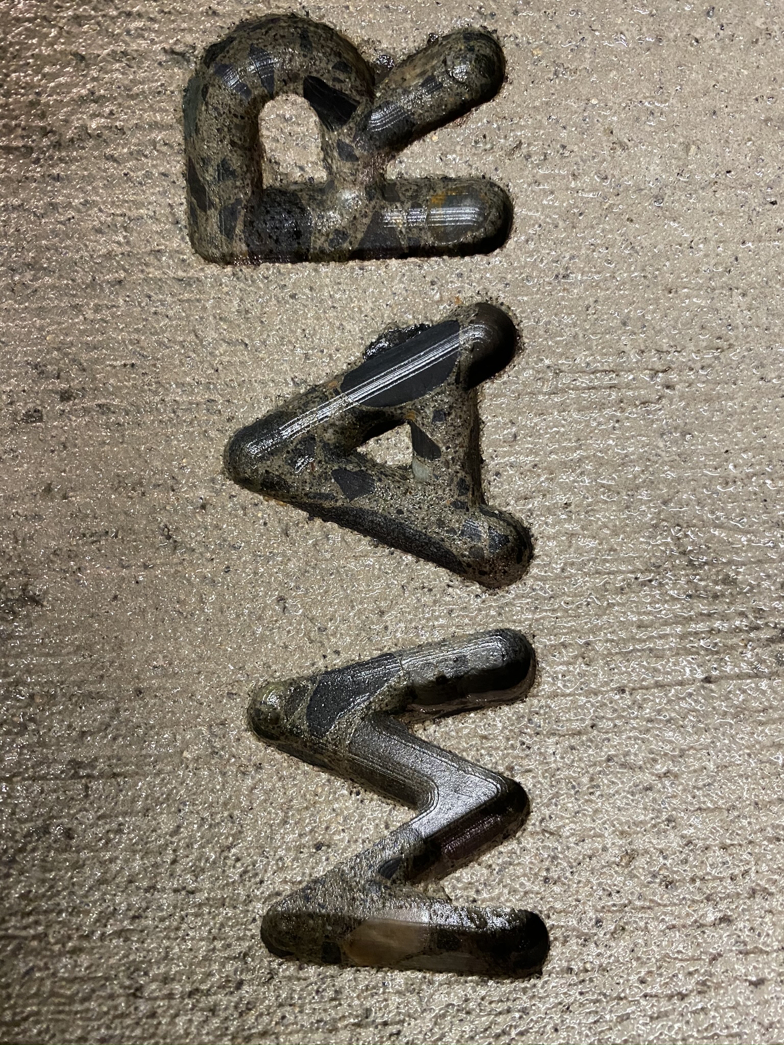
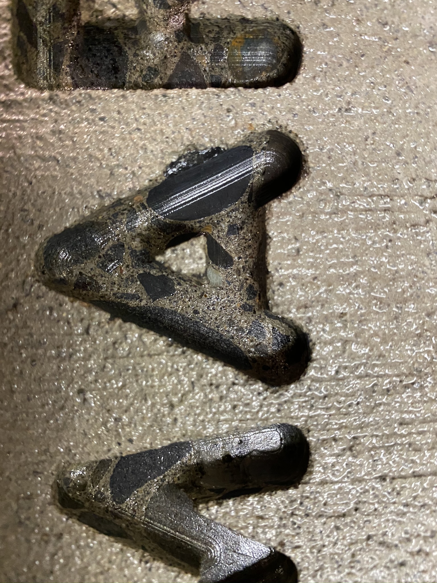
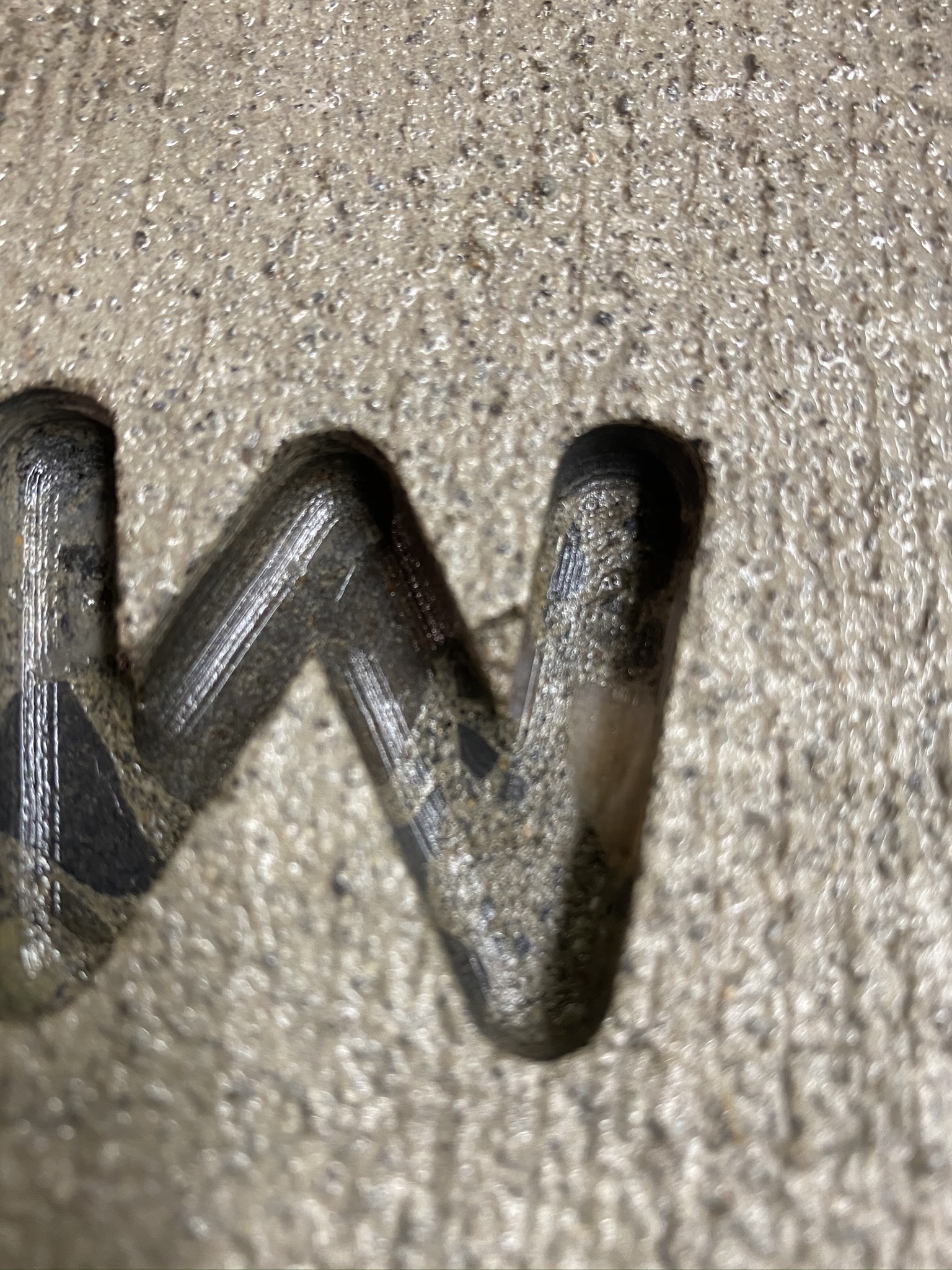
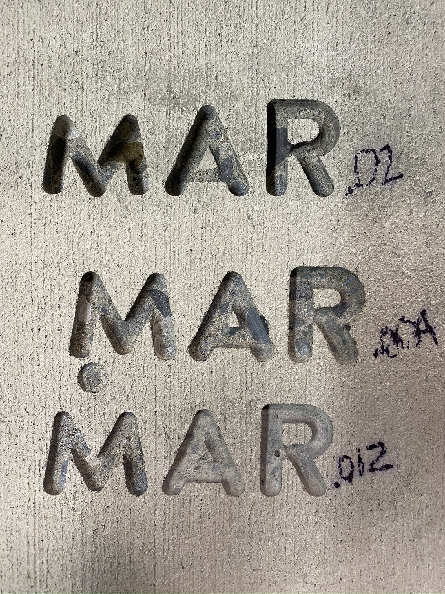
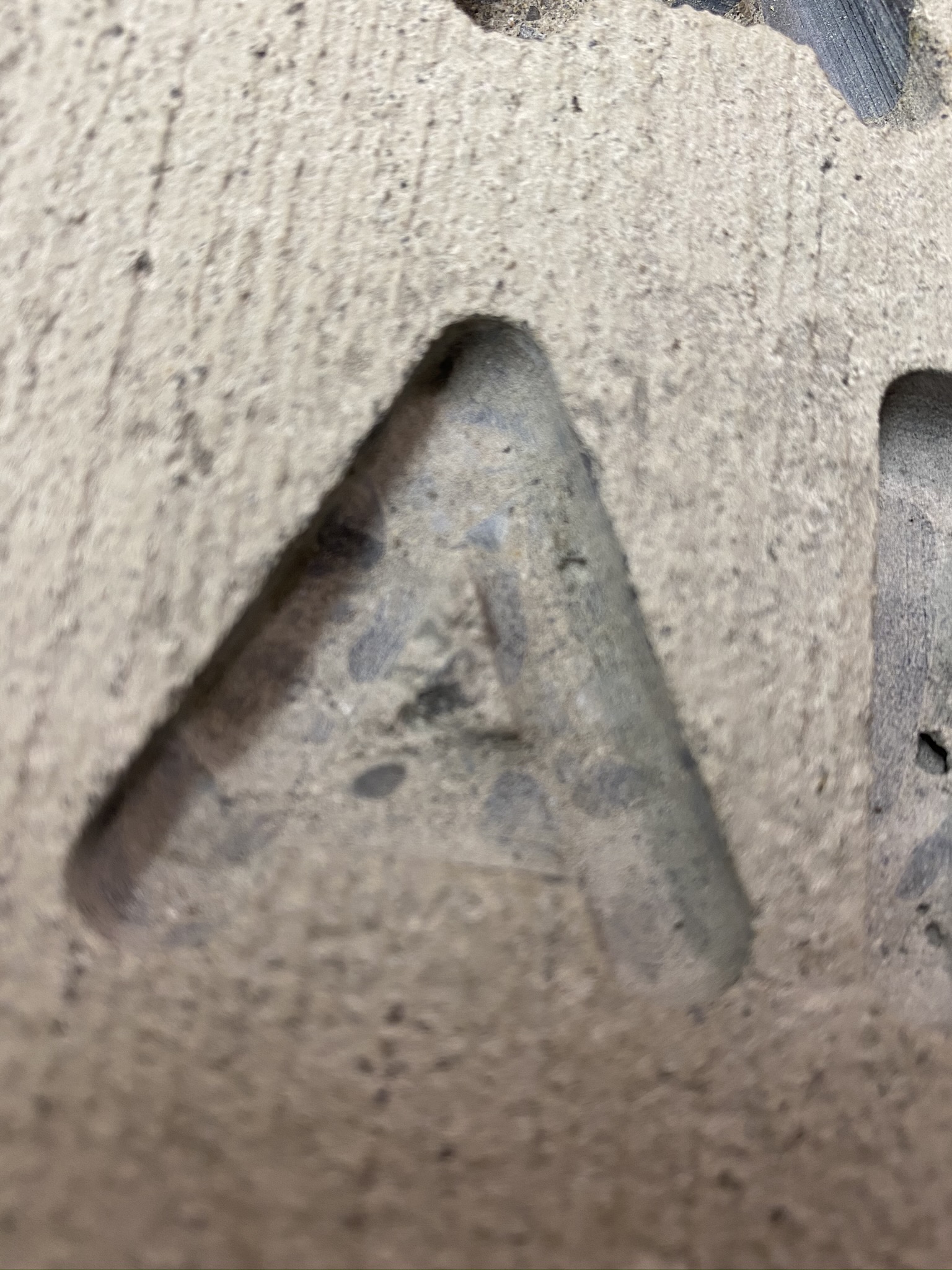
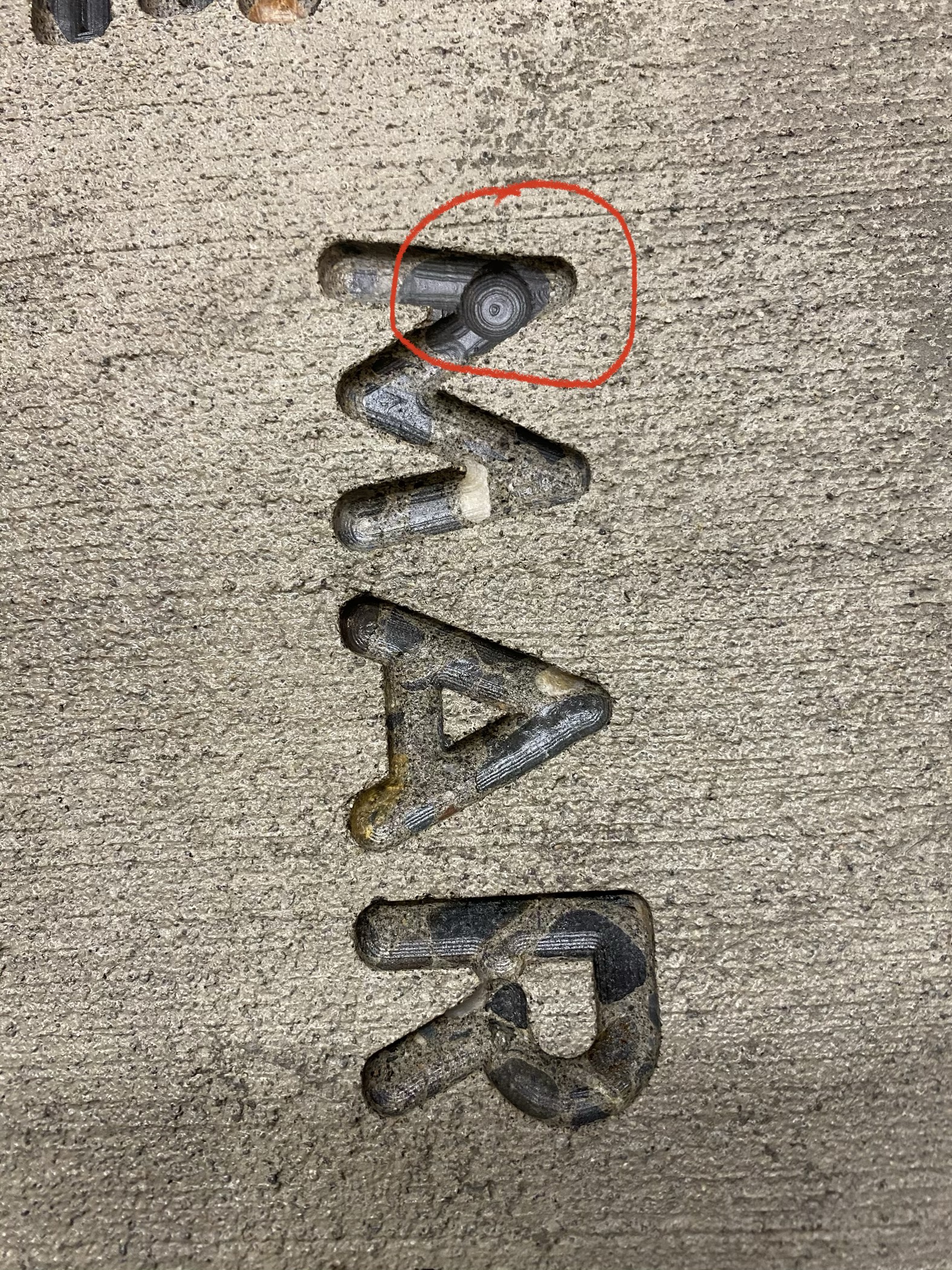
The downside is that the Z axis was skipping on all three of the trial runs Sunday. When the aggregate is hard, the forces are just too high for the stepper motor to hold. The worst attempt was made when the plunge hit a hard piece of aggregate on the plunge. Skipping like a kid with a jump rope. Obviously the depth control was, well, not in control. Need that HDZ upgrade!
The comment about the non-homogeneous material is related to the small inside of the A was knocked over during the milling process. However, this is not due to the toolpath or speed of travel this is due to the material that was supporting the small column. The top and bottom A are broken and the middle is still standing. The middle had a piece of aggregate that the center of the A was carved out of.
Here are some pictures.
Quite interesting. So 0.02" radial stepover it is, for now.
I can see how the Z axis would skip steps in such a demanding material, however: