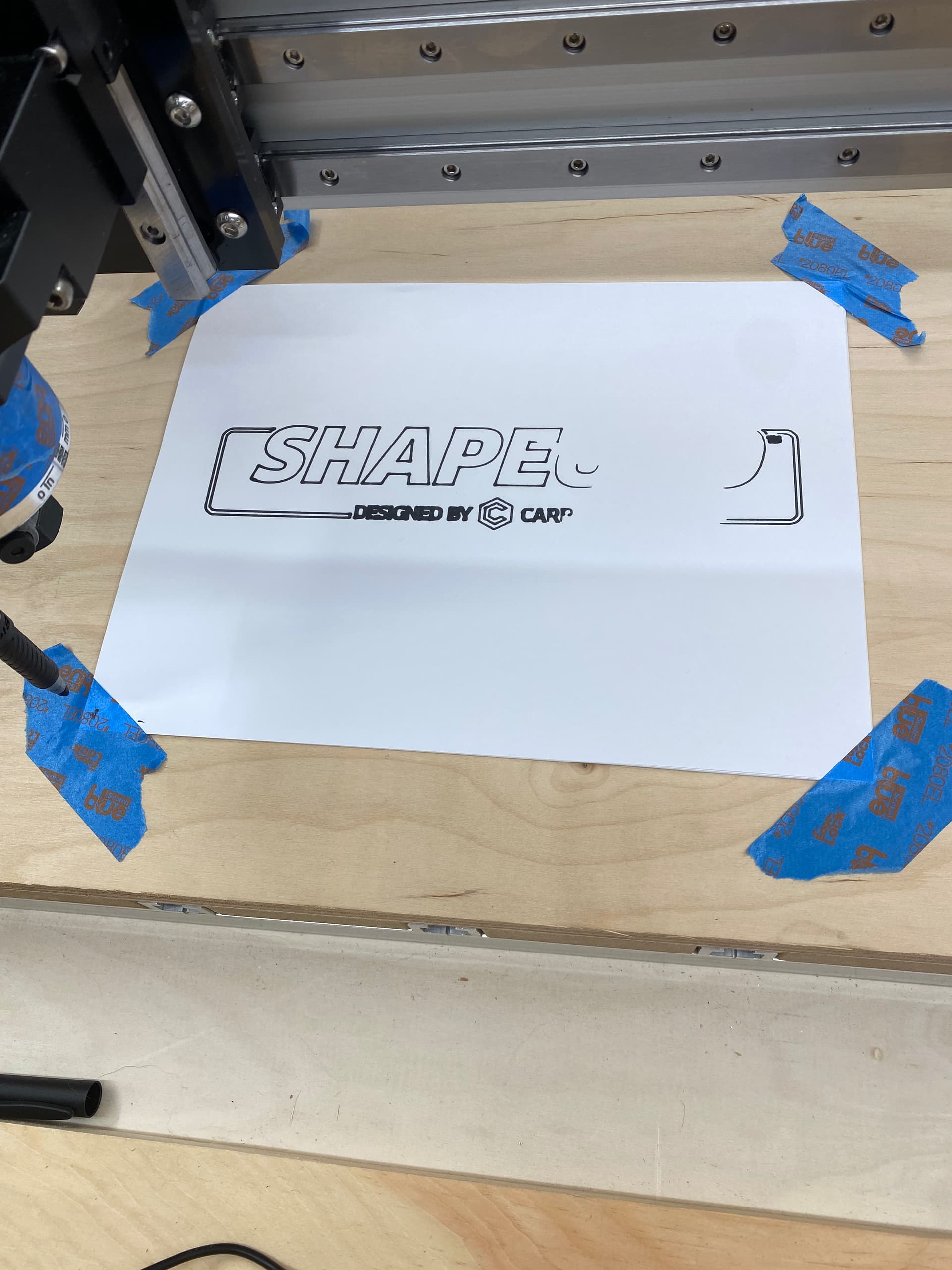
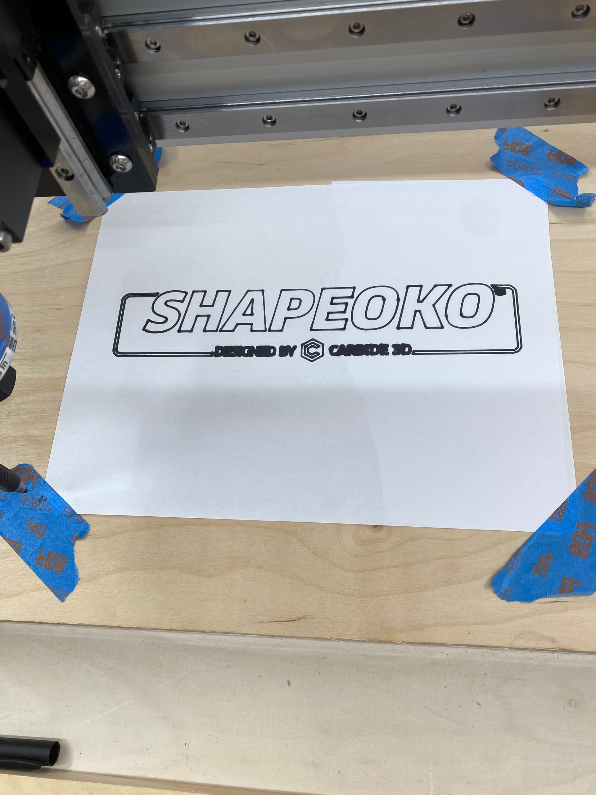
Low spot on the surface — you can put a pad of paper or something similar under it and try again if you wish, or just go to cutting — it looks good other than the low spot.
I see you are using a plywood base. Plywood is not the greatest but it will work. Most people use MDF as a sacrificial spoilboard.
Since this this looks like a new machine some have the T-Tracks and MDF in between. Some like to make a MDF spoilboard that fits on top of the hybrid base from C3D. If you are interested I have a document about making a supplemental spoilboard. It was written for a Shapeoko 3 XXL but all the instructions apply to making one for any machine. See if you find it helpful.
When you first drew your Hello World you can see that you have a low spot. That low spot will also show on your projects. Plywood once you surface it to get level it will disintegrate into the layers that it is made up of. Plus plywood has hidden voids inside that once you expose them are a problem.
Some make supplemental spoil boards of MDF others out of HDPE and some Aluminum. There are many discussions about each of these materials. The MDF is the generalist way to go. The HDPE and Aluminum are used for more specific types of milling.
This is a brand new Shapeoko Pro XXL. I bought it in November and have just run into constant hold ups and issues. I had to redo my entire enclosure, had to wait for an electrician etc.
I do have the aluminum tracks with the MDF in-between.
Thank you for the information on the spoilboard and wood differences and the document, I will take a look at the document tomorrow when I’m fresh.
“level” is not the same as “flat” or “parallel”. You want the tip of the pen (cutter) running in a parallel plane to the base. Likely there is a low spot in the plywood. Run a few fine passes over the surface of the spoil board with a bit in the collet to flatten and make it parallel to the plane of the bit. MDF makes for a nice spoil board material.
I went through the file and I have cut the MDF, I am waiting for the flycutter bit and I need to order the T-nuts. My question is how do I hold down work with the T-Nuts? Do I use the get a grip work holding kit with these or something else ?
Apologies for all the questions I am completely new to CNC and while I have been learning a lot, there is still a lot to learn.
Ive been going through your PDF on spoilboards. I made my spoilboard the same size as yours since I have an XXL pro. I did not center my board as I wanted it further away from the bitsetter on the machine so there was no chance of striking it.
I adjusted the x from 864 to 825.400 in carbide motion but it is seeming to subtract it from the left side as now it is showing 39.600 for x instead of zero when i select to 0 it and it wont let me jog it. If I set it for 0 from the left front would the number not increase as it moves from left to right instead of limiting the range to the left when i reduce the X?
I adjusted the y to 825
Bitsetter is working properly
Edit: I didnt send the configuration. Once I sent the configuration now it is zeroing where I set zero.
Edit: i went to do bit zero and goofed it up had to hit stop on machine reintialized but when i told it to go to home XY it didnt go there yet it still has the limits i put in for X and Y.
I then sent configuration, intialized machine let it run bit setter i then went to rapid position, rapid to current xy and its short again. This makes 0 sense to me
However this brings another question, I have the bitzero add on. How do I set this and how do I set the size of my spoilboard ?
I did not quite follow you on all your changes. However one difference between the two machines is I have a Shapeoko 3 XXL. The Pro XXL is different on the front edge. Now when I surface my spoilboard I made it 1/2 inch shorter so my Whiteside 6210 could go over the edge so I get the entire spoilboard surfaced.
When I surface my spoil board I remove my BitSetter for the same reason you dont want to hit it. On the Pro XXL not sure how hard it is to remove the BitSetter but on my SO3 XXL it is two set screws and it is off. I marked the position before removal so it is easy to put back and usually does not require recalibration.
The default configuration sent by CM to most C3D machines is not the actual maximum travel the machines are capable of. The X distance has been diminished for a while to accommodate the Suckit dust collection which is wider than the Z carriage. C3D has restricted the X travel so you dont crash your Z into the Y rails.
You could manually increase the size of your travel and move your machine to the mechanical limits and write down those absolute maximum travel dimensions and come up with your own configuration. You dont want your machine hitting the mechanical limits so shrink your travel slightly to accommodate this.
Another difference between the SO3 XXL and the Pro XXL is the SO3 travels quite a bit off the front of the bed. The Pro and SO4 machines do not travel as far off the front edge as an SO3.
So for the Pro XXL you need to experiment and figure out the absolute maximum travel dimensions for your Pro XXL. Possibly remove the BitSetter when surfacing. Adjust your spoilboard dimensions based on your configuration to be able to fully surface your spoilboard. Design your spoilboard for the Pro XXL based on your dimensions. My concept of the spoilboard does not allow the absolute maximum cutting ability of my machine but restricts it so the entire surface can be reached. The small amount of maximum cutting ability is not a real loss because you seldom cut to the absolute edge of the machines’s ability.
I didnt realize yours was an SO3 XXL so my spoil board is smaller than it could be but I currently do not have anything big to CNC.
I am about to run the program for making the holes in the spoil board. Last night I used bitzero and set the configuration. I shutdown the machine disconnected my computer and then restarted carbide motion today. I ran bit setter and now when I jog to current xy it seems like it retained the settings from last night but when I go to run the file I got a warning about setting zero. However now when I go to load the file I get no such message.
Does carbide motion retain the settings from the last run or do I have to change to the probe bit run bit zero every time I have shut the machine off and turn it back on and then run bit setter again ?
Cm remembers your last time you set x y and z zero. The homing switches are pretty accurate but repeatability is dependent on those 3 switches accuracy. When powering on your machine best practice is to use rapid position to check. The z rapid position is 0 +6mm so make a 6mm spacer to check.
I have noticed that if you turn off bitsetter in config the z zero is no longer set properly. That is a special case and not usual.
FYI. The first sentence of my pdf says the instructions are for an SO 3.