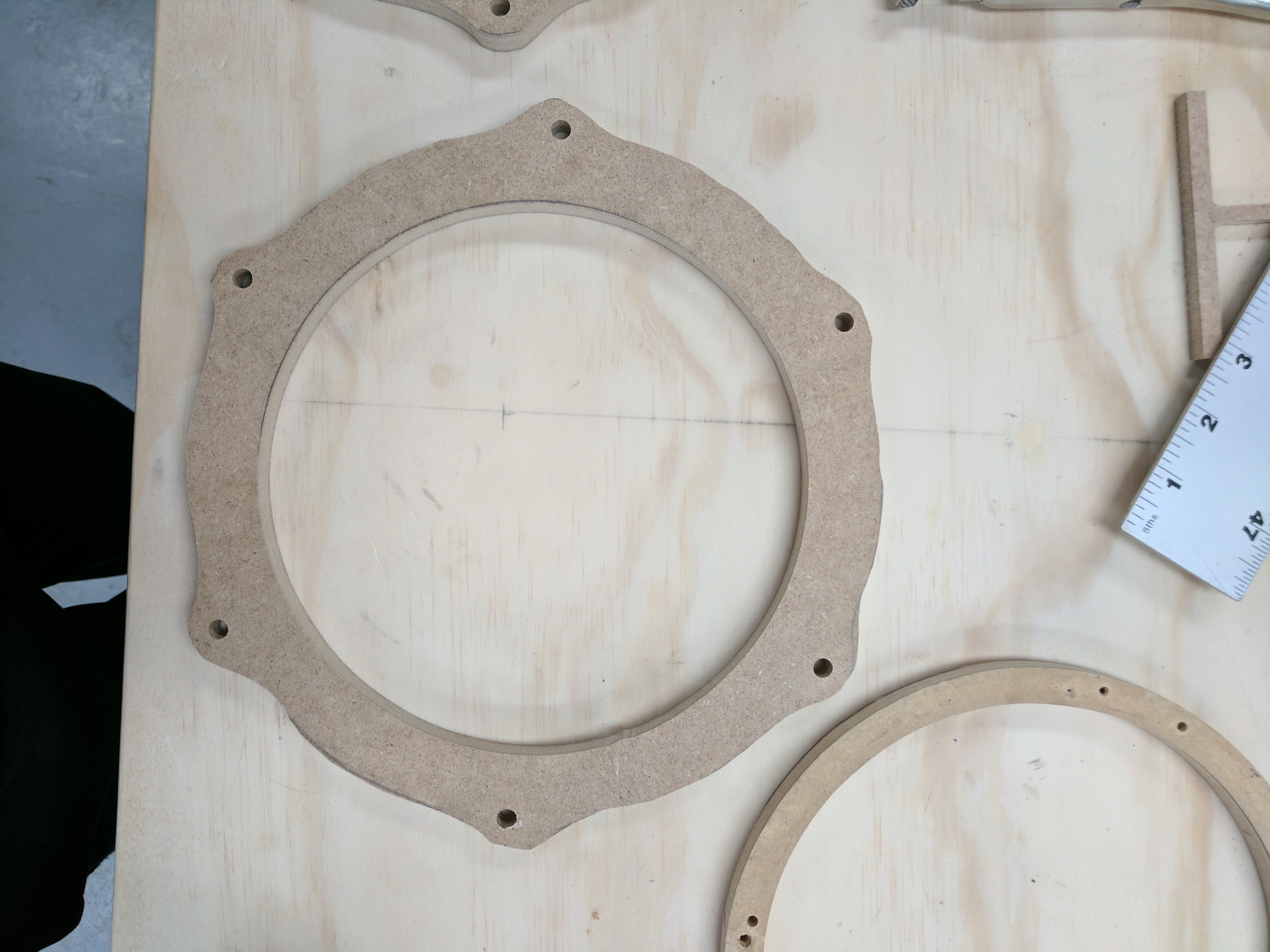
Im a new user to carbide create and shapeoko and unfortunately already having a tough time. Ill be using this machine for work. At my job we have a bunch of speaker mounting bracket templates that we use to make new ones, and I wanted to transfer these into carbide create to make life a lot easier in the future.
The problem is I have not yet found a simple and easy way to do it. I tried the inkscape program, but didn’t get too far with the trace to bitmaps option.
Manually making the curves and lines seems like a LONG process, that also doesn’t seem too effective.
Only other thing I thought about was using magnetic selection tool in Photoshop, filling the selection with a solid color, and then transferring to inkscape just to save as a svg file.
Are all the templates the same? Your picture suggests there might be at least two different ones. For someone familiar with drawing in Inkscape, Illustrator, Freehand or Corel it’s an easy task to draw those. I use Illustrator and will draw the main one in your picture for you if you supply the EXACT measurements for the inside diameter, the outside diameter, the spacing between the hole centers (across from each other) and the diameter of the holes. Also, do those holes form an exact hexagon?
No, not all templates are the same. They differ for each car, as well as location of actual speaker, the picture I attached is just one to show an example of what I want to make.
While I do appreciate the offer to draw it up, I’d like to know how to do it myself as there will be many of these in the future , maybe even in paper form, that I’ll need to create.
Is it all basically freehand? I know Photoshop has a magnetic selection tool which allows you to follow the edges and it seems like it’d help, but I thought there might be a better and / or quicker way.
Take the photo, place it on a background layer, scale it to the correct size (photographing against a grid or including a ruler will help with that, see https://www.shapeoko.com/wiki/index.php/Carbide_Create_Photo_Tracing ) remember that symmetry and regular dimensions are your friends.
Position the photo so that the center of the hole is at the center of the page.
Draw in a circle of the proper measured diameter and center it on the page
Draw in the first bolt hole, measure its distance from the other bolt hole and place it half that distance from the center of the page, count the other holes, calculate the degrees of rotation needed, clone it in place, rotate the clone around the center of the page (easiest way to do that in some programs is to draw a box the size of the page and rotate it at the same time) — in Freehand, “Power Duplicate” would now activate and you would tap Command d as many times as needed.
Clone the original circle, offset the path of the clone by the width of the part along the main portion, clone this and send the clone to the back (you’ll need it later)
Select all the bolt holes, clone them, offset their paths by the thickness of the part at its narrowest around the bolt holes
Draw a rectangle which is centered on the page and which crosses the outermost circle at the point one would want a path to soften that edge. (fastest to do this when one is making the bolt holes, but we’re trying for simplicity here) clone, rotate and dupe it as many times as needed.
Clone the outermost circle, select the rectangles and the enlarged bolt holes and do a Boolean intersection — you should now have the basic shape one wants, one just wants to smooth it a bit.
Delete the point there one of the bolt holes intersects with the outermost circle — it should be constrained by the point where the rectangle intersected it — make this region a smooth connection. Draw in geometry to isolate only this one half (from top of outer circle to rectangle intersection. Trim it down so as to make an acute triangle for the balance of the part with the point at the center of the page.
Clone it, flip it, drag it so that the point is at the center of the page
Union the two parts, clone the union, rotate and duplicate it as many times as needed, get the original outer circle from the background layer and union it with the rounded sections you’ve just made.
Select all the bolt holes and inner circle, bring them to the front and punch them out of the shape, select everything else and delete it or send it to the background after using the extra geometry to verify symmetry.
Takes longer to type up than to do — when I taught using Freehand I’d have my undos set to 100, and would go through such tasks at full speed, then undo back to the beginning, then step forward and explain each step.
Taking a photo of your template on a high contrast background would make it much easier to clean up in photoshop. You make also consider throwing it on a scanner.
What are the elements of the template that demand precision? Just the center hole and the bolt holes? Does the outside profile have to be accurate? It looks in the photo like it was a hand-done bandsaw rough cutout.
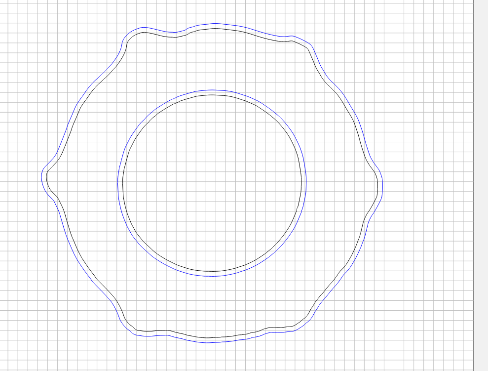
I would draw (in Inkscape) the inner and outer circles and a hexagon (all accurately sized) and align their centers. Then draw the hole circles and position them on the hexagon points - then delete the hexagon. Then draw one of the bumps that projects out around the hole. Have that bump drawing overlap into the outer circle. Then duplicate and rotate it five times around the center of the whole. Then join/weld/merge the bumps with the outer circle and you have your shape. This shouldn’t take more than a couple of minutes, assuming you’re familiar with the drawing program.
The precision we need is the middle circle (for the speaker to slide through), and then the smaller holes for the screws. The general shape, usually doesn’t have to be precise as it’s really meant to get around parts on the door, such as wiring, bumps or whatever else.
I’m open to options for different programs such as fusion 360, if it makes life easier for this and future projects. I’m.actually trying to compare the two see which would be better.
So I was messing around more today and I managed to get something going on, using a combination of Photoshop and inkscape, but my problem now seems to be scaling down to the correct size. Any suggestions?
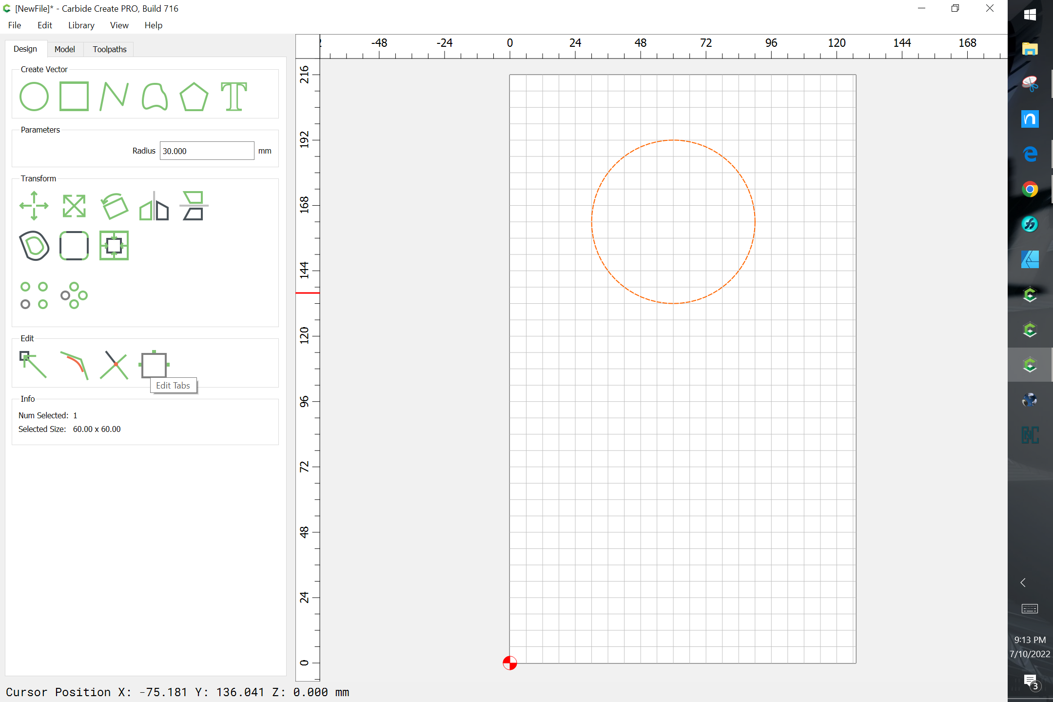
One thing that I’m still trying to figure out is how to add tabs easily. I read through one of the topics here but some reason i dont know how to apply it to my project.
I have the traced image in but cannot not for the life of me figure out how to add tabs, Maker cam does this so easily and this just seems like a royal pain
You can DL the free version of Artcam (Artcam.com). For your project it will do the tabs and it has a nice simple bitmap to vector conversion tool. I don’t use Artcam, but for the price this is a really nice tool.
Frustrating that the tabs are a necessary part of cutting all the way through your piece and not every project has holes in them that you can screw down. I guess I am going to have to use a different program!
A lot has changed in the 5 years since this thread from 2017, you might want to review the tutorials, which include (section 9) tabs.
Wonder how that all worked out for @coderedpl? Today he could scan the part and use CC’s built-in image trace and scale to match the original for his multi-part library
Those templates look pretty beat up & out of shape. I wonder if that shape is intentional or just a result of use?? Seems like it would be really fast to just draw it up as initially designed & get a much nicer end result.