Help Tramming Shapeoko Pro XXL

I am attempting to Tram my Shapeoko XXL. But I am not sure I am doing it right. I did use the magnet and went through zeroing it out.

Should it be trammed to the original MDF table slats or to my wasteboard on top?

When i checked the level of my wasteboard the bubble is off on the X axis but almost centered on the Y. See pics

When checking Tram on X it has the differences show in the pic

When checking Tram on Y the Northernmost dial indicator is not even moving by the time the other one reaches 0.

I am not sure where or how to adjust the tram on the shapeoko.


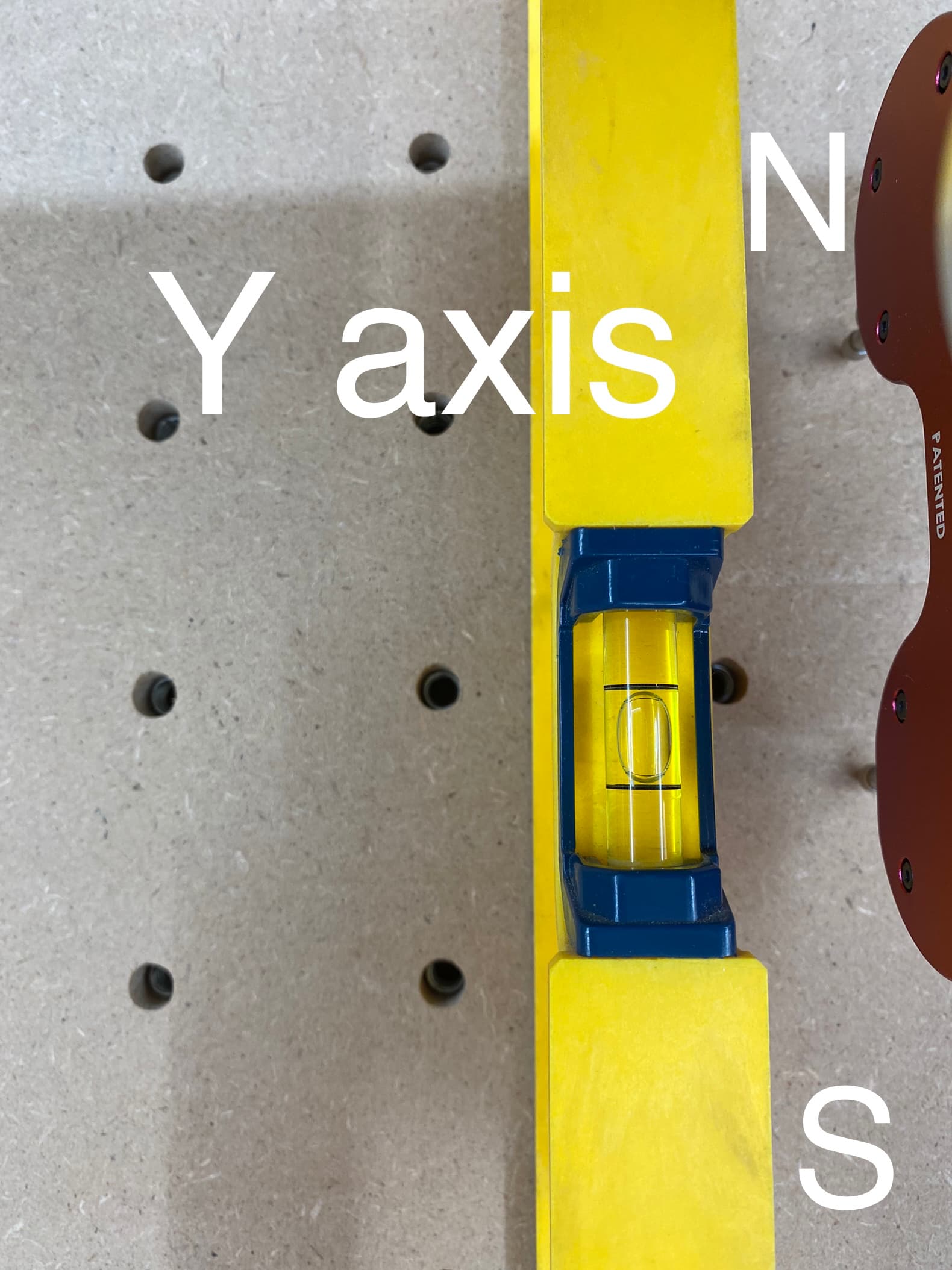
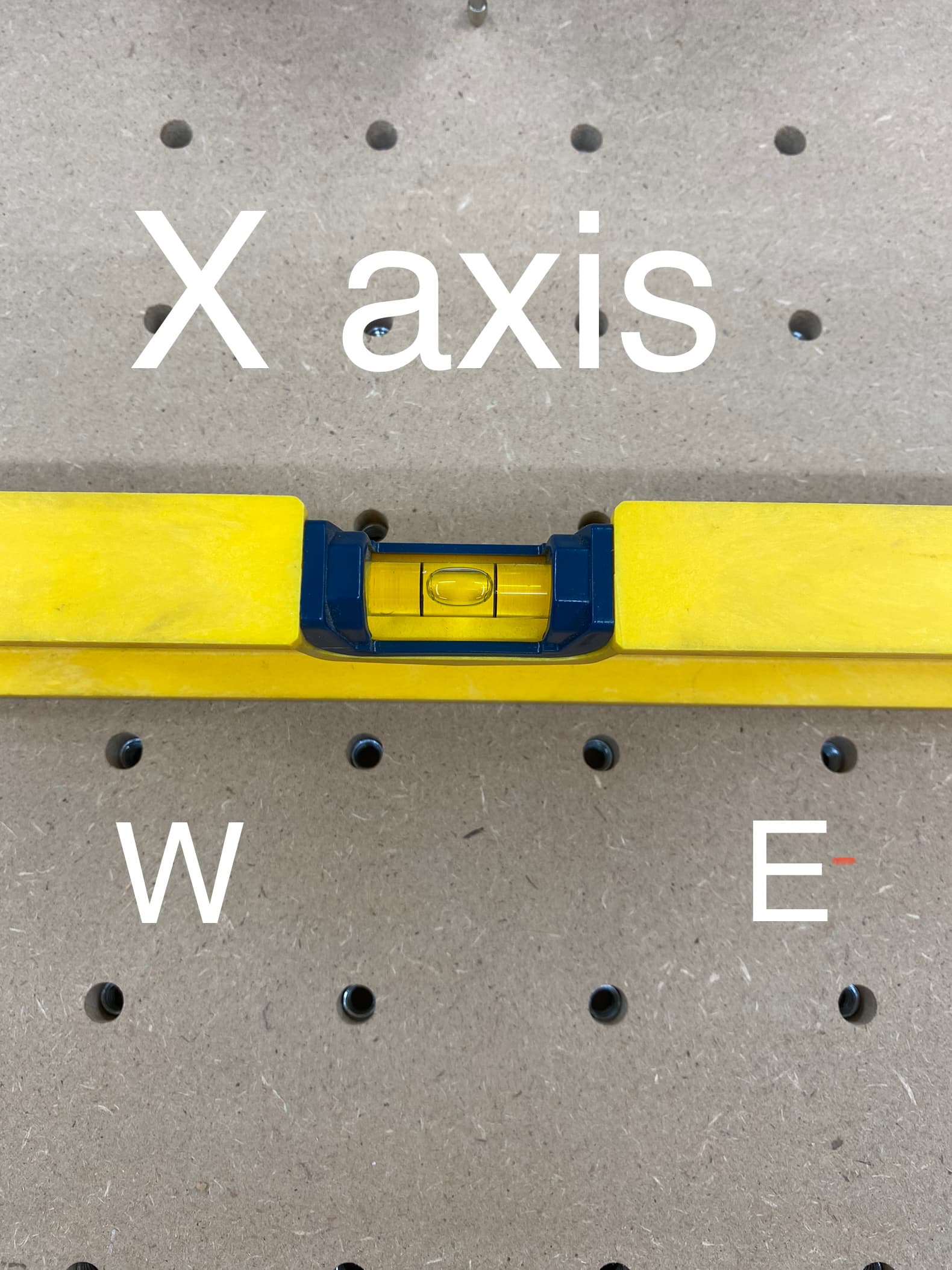
1st, put the level away. It means nothing. unless you’re using it to judge the flatness of the wasteboard.
That or a precision straightedge…

Either one. But the surface should be recently surfaced flat, and then checked for flat.
Use the straight-edge or level to check flatness front to back, side to side, and also on diagonals.
If not flat, shim the machine to get it flat.

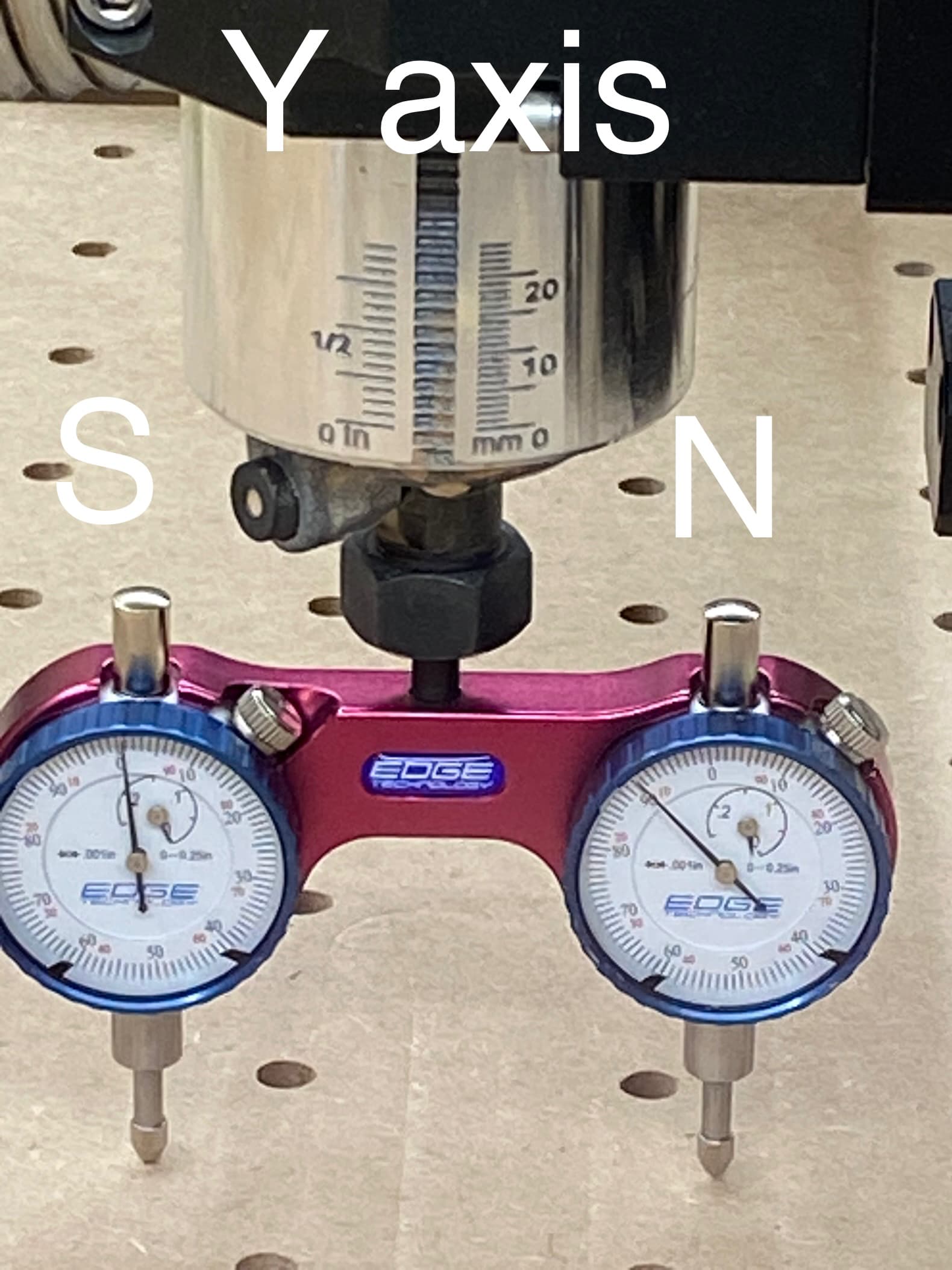
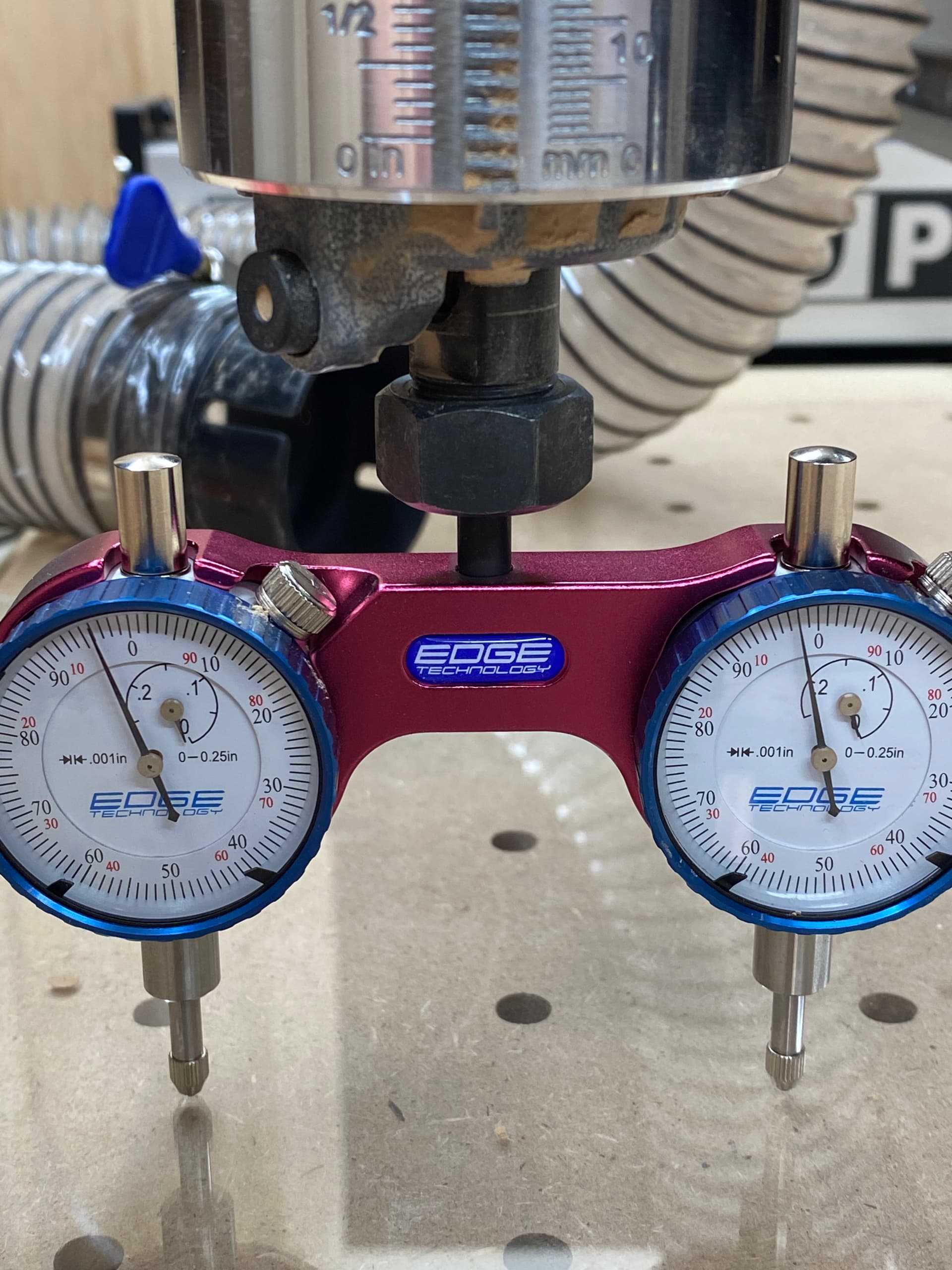
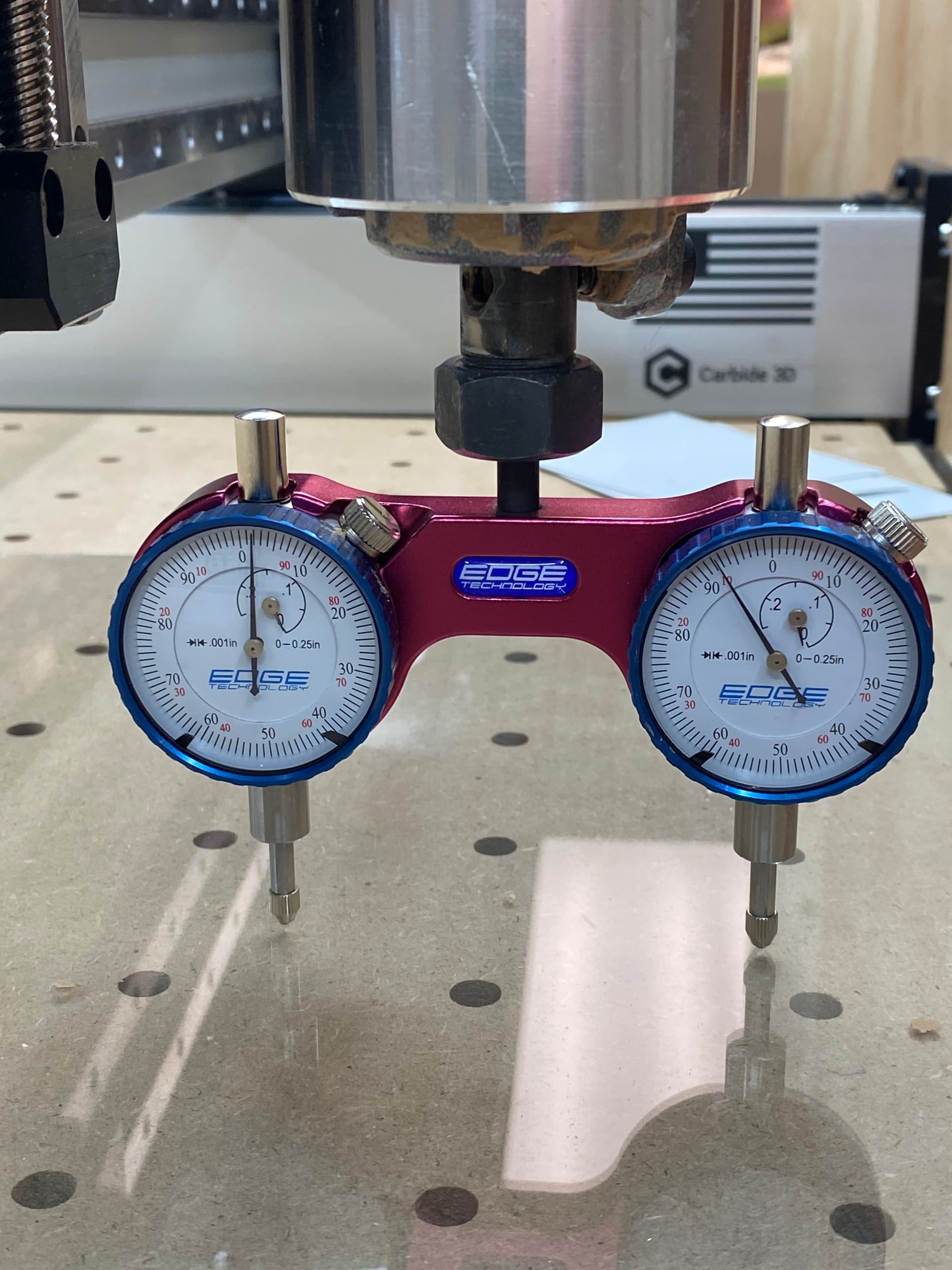
Next, calibrate your tramming tool. Move one probe down to a solid surface (1-2-3 block, parallel, anything flat & solid) until it reaches zero, or moves the needle a bit & set the dial to zero. Lift up, spin the tool, and set the other probe to the same zero.

Now when you lower your probes to the table, lower them until the 2nd dial reaches zero, and read the other dial for your “High spot”.

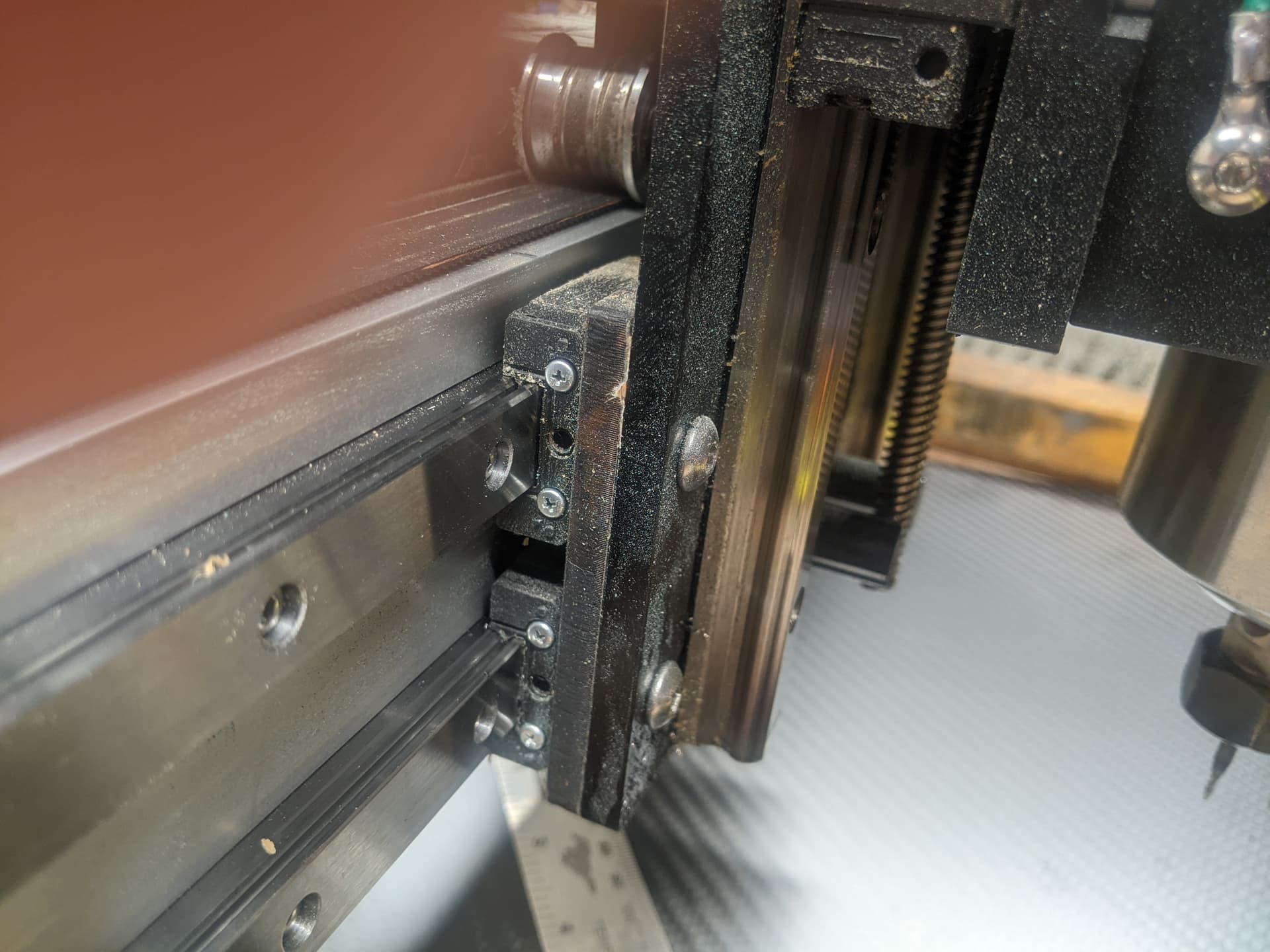
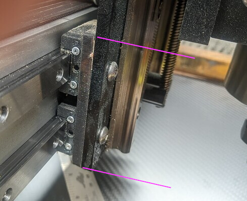
I do Y first on my HDM, and I shim the Z axis mount to get it even. If you shim the motor mount, the axis itself is still moving at a slight angle. Your tool will be perpendicular, but not at the same Y position as it moves up & down.
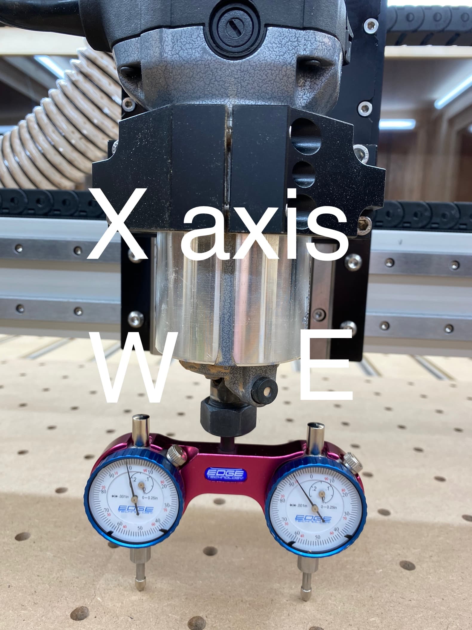
For the X, I crack 3 of the 4 motor mount bolts about 1/8 of a turn or less, just to loosen them, leaving one of them tight. Gently tap the motor mount until the indicators are even, then re-tighten.

Not sure the size of your indicators, or the tolerances you’re shooting for, but I would say if either axis was off by more the 0.005" I would resurface the slats or spoilboard after tramming.

Now you’re ready to calibrate the 3 axes, and check the XY for square (If you choose to do so.) :slight_smile:

6 Likes

I was trying to determine how level the MDF spoilboard was. I did surface it with a Whiteside FlyCutter a few weeks ago and sanded it down smooth since there was slight lines between the passes since the router is not square to the surface and this is where the confusion is coming in. How can I properly tram the head of the Shapeoko if my MDF is not perfectly flat? That was the reason for the pics of the level is to show how level it is as I am not sure if I can get it dialed in any more level.

I did the process as you said above using the magnet that came with the pro tram to set zero for both indicators.

What Z Axis mount are you referring to ? could you show me ?

As far as how far off it is on the X Axis I was able to straighten it out.

The Y I have not been able to straighten out and it is quite a bit off. I think it is -.009 judging by the 9 marks on the right dial gauge versus the left one which is at 0. It seems the South facing end of Y axis is higher and the North end is lower as the North end is not moving.

While I’m very new to this, I’m currently initiating the same process, and have seen people first surface the spoil board, and then place a piece of glass (approx A4 size or so) on the spoil board, and use that as a tramming guide. My understanding is that it averages out the flatness of the MDF spoil board, and serves as a smooth and flat surface upon which the gauge pins can easily travel.

Also, I’ve found this resource helpful: How to Tram Your Shapeoko - YouTube

2 Likes

Yes, glass works nice. But make sure to measure it’s thickness in a bunch of spots to make sure it’s true. Old glass can sag & be thicker on one edge.

Anything else that you know is flat & parallel, like a metal ruler, framing square, would help you eliminate the scallops from the flycutter.

It looks like on the Pro, the slides for the Z axis mount directly to the plate for the X axis. No shimming to be done there

I do recall seeing something about twisting the whole X axis gantry on another topic. Check the manual for your machine to make sure.

1 Like

I bought brand new glass today, i then set zero for both sides.

I tried to align the Y axis but it is so far out that even loosening the bolts on both sides of the X gantry can’t fix the difference in Y. See video for how much the southern direction of Y is down before the northern side starts to move. I have checked the level of the bed unless there is something more precise then a bubble level the surface is level.

Watch the video to see how much the gauge on the left moves before the gauge on the right does

How do I fix this? Do I have a bent x gantry or something?

To tram the Y, I shimmed the Z plate with paper, until I got it where it needed to be,. In my case, I had to shim the top out. Yours looks like the bottom needs to be shimmed out.

3 Likes

I was wrong about the carriage. If that picture is correct you can shim it.

image

Looks like it was about 0.044" off over 3" using your tramming tool.
I’m not into blind trust much, so I would spin the tramming tool around 180° and check it again.

So measure the height of your X axis carriage (magenta in pic).

Shim = 0.044 x height / 3

1 Like

Ok so I tried shimming it tonight.

When I have the Y axis so the dials are facing to the right i get this reading

When I spin them 180 degress to face to the left I get this reading…

Why is there such a big discrepancy? What am I doing wrong ?

I had a thought… is it possible my spindle is bent ?

It could be that either the shaft on the dial indicator assembly is bent, or the collet isn’t true, or the trim router is no turning true — check the runout of the collet and trim router using a dial indicator?

How do I check runout ? What do I need part wise to do this ?

I can not picture in my head how a bent spindle, shaft, or runout will stop you from tramming your spindle.Wore out bearings? yes. Warped spindle housing, yep.
I would reface off your spoilboard first, and NOT sand it smooth. then put your sheet of glass on the spoilboard. I would also put a test indicator in the spindle, and run it over the glass to verify that is is level with the gantry. Then I would begin tramming the spindle.

Just my line of thinking,

I would also put a test indicator in the spindle

What do you mean by this ? Do you mean the tram gauge?

I only currently have the Edge Pro Tramming gauge I do not own any other gauges and I am very new to all of this so I don’t really have any experience tramming or any other setup/ adjustment of a CNC.

Whats happening with the tramming makes little sense to me. When I rotate the tram to face to the right on the Y axis it reads one thing and then when I rotate it 180 degrees so it is facing to the left I get a completely different reading. Are the indicators not on the same exact spot ?

I guess I will try resurfacing the spoilboard again and not sand it.

It looks like the Edge Pro gage is pretty close, it just needs to be dialed in to start.

Not sure what you meant by calibrating it with a magnet.
But if you put something solid under one of the probes, and move your machine down until it reads 0.000
Set your Z zero on the machine, or note the Z value.
Raise your Z and spin the gage around 180° (If you raise Z 0.100 it’s one click to move it back)
Now lower the Z to the same position it was, And assuming the needle has moved, turn the dial face so it also reads 0.000.
If the second needle doesn’t move, move down until it reads 0.000, then repeat the process for the other probe.
Either way, they should both read 0.000 when rotated checking the same object.

Now when you bring them both down to your glass so one of them reads 0.000, when you spin it they should switch.

1 Like

Not sure what you meant by calibrating it with a magnet.
The Edge Pro comes with a little magnet that you are supposed to use to calibrate it with.

I put it in Y axis orientation with only one side of the gauge touching the magnet which is supposed to be square to the surface and the other side is hanging off. I then bring it down and in a video it said to get it to 10 then set for zero. Lift up rotate and set for zero again, except that when I set for the same distance the opposite side the needle does not move. In the second pic above the gauge needle wont even move on the right side of the gauge yet when it was flipped 180 degrees it was almost the same measurement for both gauges. I hope I made that clear.

May I suggest simplifying your problem by eliminating a calibration for now?

If you use just one of the dials on the tramming gauge then it doesn’t matter if the gauge is set up properly, it will need setting up to have both dials zero correctly.

Just pick one (probably the left one as it moves first) and rotate in the spindle watching that gauge and ignoring the other. I tram my machine with a single sided arm with a single dial gauge in.

Once you get it all set up I’m sure the whiteside is a bit quicker and easier to read but for now, I’d simplify the problem by eliminating a variable.

HTH

6 Likes

And now I have a new problem. I finally got it trammed and now the X axis is binding and not running smooth WTF!

2.64mm thick cardboard shim. Once I removed the shims the binding stopped. I have no idea now how to tram my machine now. It is apparently out of tolerance by quite a bit and putting the shims in is causing the Z plate to bow causing the linear rail to bind so I can’t shim it to where I need to, to properly tram it.

I honestly do not know what to do anymore with this machine it has been just one problem after another.


Please write in to support@carbide3d.com and let us work through this w/ you.

1 Like