The machine is mostly set up but I have a question regarding setting up the media. I think I have the x/y correct but what is the proper way to assign the Z height? Do I set it up with the bit in the router or remove the bit and nut then lower the carriage to the top of the media?
Start with the endmill in the machine, move to where you want the reference for Z zero to be, then lower until you can get a repeatable setting. Methods to use:
- use a touch plate: Shapeoko CNC Router, Rigid, Accurate, Reliable, and Affordable (Carbide 3D will be releasing one soon)
- use a piece of paper: Shapeoko2 - First Job
5.Lower your Z-axis so the tip of the end mill mounted in the spindle just touching the material. A good way to gauge is to lower it down onto a single sheet of paper. As the bit gets close to the paper, try moving the paper around slightly. When the bit prevents the paper from moving, then you’re at the right height! This also usually works out to leaving a paper-thin thickness connecting the cut-out part to the balance of the material.
- use a cylinder of known diameter — jog the endmill against it, then incrementally lift and jog until the endmill just passes over the cylinder — this is a good way to set Z-zero when you want to reference off the bottom of the material and material thickness is a bit variable, say when woodworking and you are making rabbet joints
I believe this is discussed in: http://carbide3d.com/docs/tutorials/tool-change/ or it’s in one of the videos: Getting Started with Carbide Create or it’s in the tutorial: http://carbide3d.com/docs/tutorials/makey/
This is how I set up the machine but it isn’t cutting the correct depth. It is barely skimming the surface, sometimes it doesn’t touch it at all.
I see the cartridge dropping but it is starting at the wrong height. It’s almost like the z 0 setting is reset to the 12mm up position after I hit run.
In that case, it’s more likely a confusion in the file setup — where does it have Z zero set to be?
Your setup has to match that.
It’s quite easy to inadvertently change that in Carbide Create if the drop down menu gets the focus and one touches the scroll wheel.
If you still have problems, please post your file and a step-by-step of your process.
1 Like
Think of your Z zero as “front left bottom”
I touch the tool to the top of my material, then zero Z, then move down to the bottom, or the depth you define as your “geometry thickness”. This gets a perfectly repeatable setup, every tool, every time. Just remember to rezero Z for every tool change. After a while, it will become second nature, and take almost no time to accomplish.
I’ve tried to use other locations for my zero in meshcam, but the only one that works consistently is the front-left-bottom.
Sometime I take a risk, and use the center. That usually works as well, but remember: meshcam really REALLY hates making negative dimensions.
1 Like
Yes, I’ve set 0/0 at my front left. The x/y seem to be cutting in the correct position. Z is not cutting at the correct depth. Should I be setting the Z zero on the media i’m cutting or on the table?
I’ve been setting the Z zero on the media.
I tried to set the Z zero on the table (waste board) but the end mill is too short? If i’m setting Z zero on the waste board should I drop the lower the end mill from the collet?
If you’re having trouble reaching the wasteboard with the endmill you should add a spoilboard.
If it’s a small part you could work up a fixturing plate.
You need to get the tip of the endmill to a known offset of the desired Z-axis zero and then set that based on that, and it will then need to be able to move to the lowest cutting depth in the file.
Apologies, I don’t think I’m doing a good job describing what i’m trying to do.
I have a piece of MDF clamped to the table and do the following.
- bring the router to the front left corner. Drop the router to the MDF and zero the x-y-z values.
- run the program
I have the file set to cut to a depth of 0.4". When I run the file it barely cuts the surface. While looking at the router I see it going up/down but it is starting at a much higher point than when I zeroed out the value. It’s almost like it sees the zero value at the up 12mm for end mill replacement.
Please check the origin in the file. Or post it for us to examine.
I just ran it again and it appears it’s starting at the tool change (12mm) position. Here is a copy of the file
CircleTest.egc (4.0 KB)
It’s difficult for people to see what’s going on directly from the .egc file. Please post either your .c2d file from Carbide Create or your Gcode. To get the Gcode, in Carbide Motion with that .egc file loaded, click the view G-code button and copy and paste to a text file.
Here you go. Appreciate your time.
Circle Test.c2d (4.3 KB)
You said you have the file set to cut a depth of .4" but the .c2d file in toolpath #7 shows a max cutting depth of .1", but toolpath #8 is set to .394" so you are correct on that one. Your circles in the design are set to a radius of .157" which is fine, since you are using the #201 bit with a .25" diameter. Just to make sure, your stock is setup to be .5" in thickness in Carbide Create. Is that how thick your MDF board is that you are using? It should not matter though, as if you are zeroing correctly by just touching off using a piece of paper as described earlier, you should not have an issue.
Will or one of the more prolific users should double check me, but I think your .c2d is fine, leading us down the path of maybe a bad machine setup. A video if you can swing it is also usually very informative and helpful showing what your machine is doing.
1 Like
That is correct. One circle is supposed to by 0.1" the other is 0.4". The 0.1" circle isn’t cutting at all, the 0.4" is surface cutting only. I think the mdf is closer to 3/4" but since i’m only cutting to a depth of 0.4" I didn’t think it would matter.
Will shoot a video now.
How do you attach a video? It’s not allowing me to upload.
I don’t know if you can share directly. May require using a host like Youtube. But you should be able to set it so that only those you give the link to can see it.
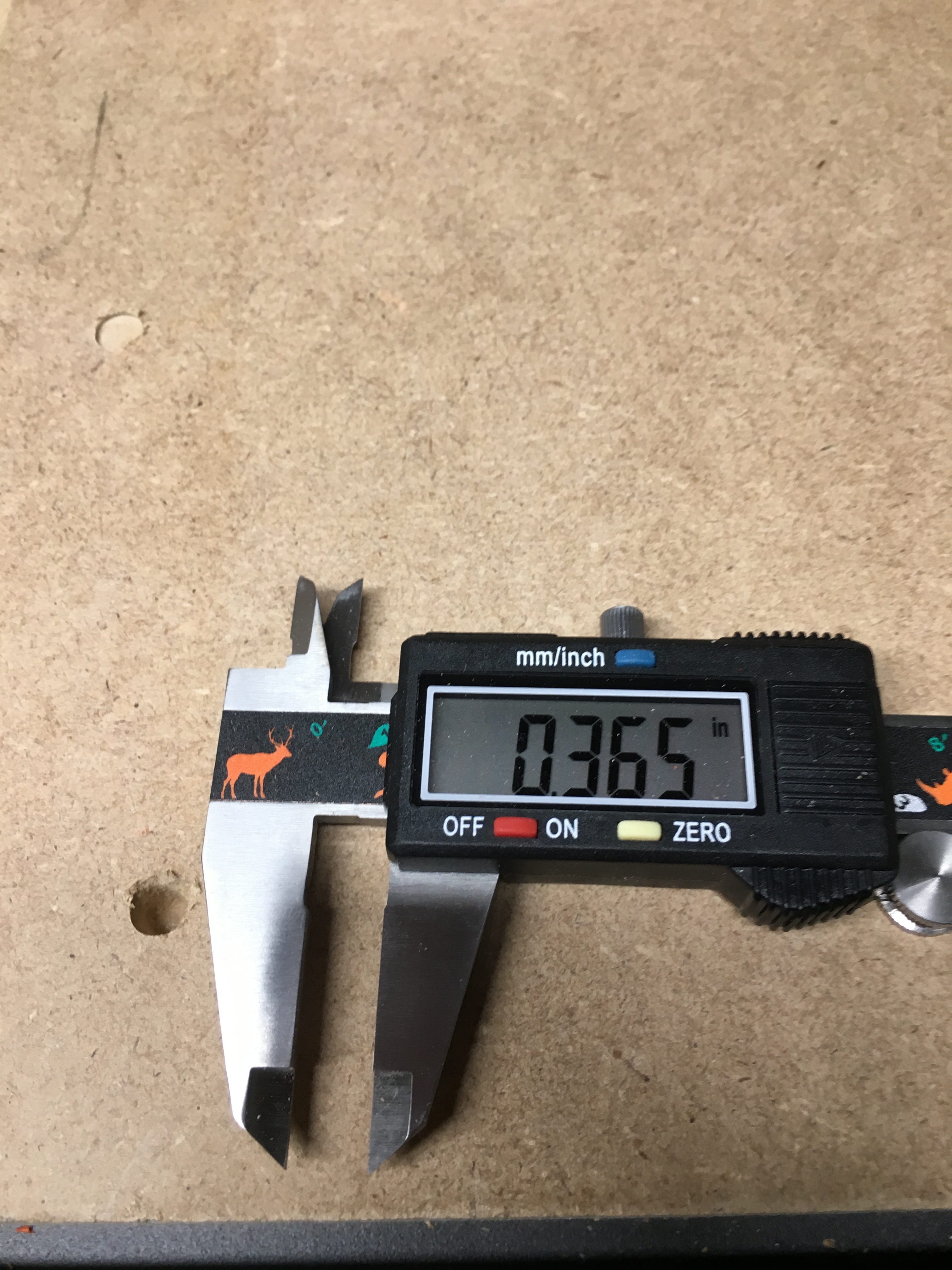
I just ran your file on my machine…turned out fine. Here is a picture. You can see the low depth hole in the top left, and the deeper one next to my calipers. I measured the depth to show you how it came out. I was in a hurry, so the depth is not exact, but close enough.
1 Like
I think i’ll delete and reinstall carbide motion and see if that works.
Don’t forget that they just released a new build of carbide create the other day. May help to get the latest one. I was using the previous one.
I wonder if the new version is creating the error. I just downloaded it the other day.