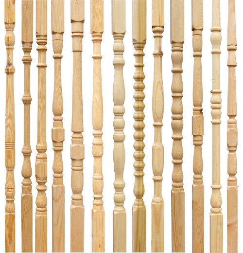
Now that I am feeling very accomplished with 2D designs, it’s time to move onto some more complicated stuff. How do I cut spindles?
I need to cut some that are quite small (8 inches tall) and a few that are much larger 4+ feet. It’s okay with me if they are halves that I can glue together. What software do you recommend for designing the parts? I’ve not really delved into importing STL files with CC Pro but I assume it should be fairly straightforward to design something like this in a 3D CAD program, export as STL, then import for tooling and cutting?
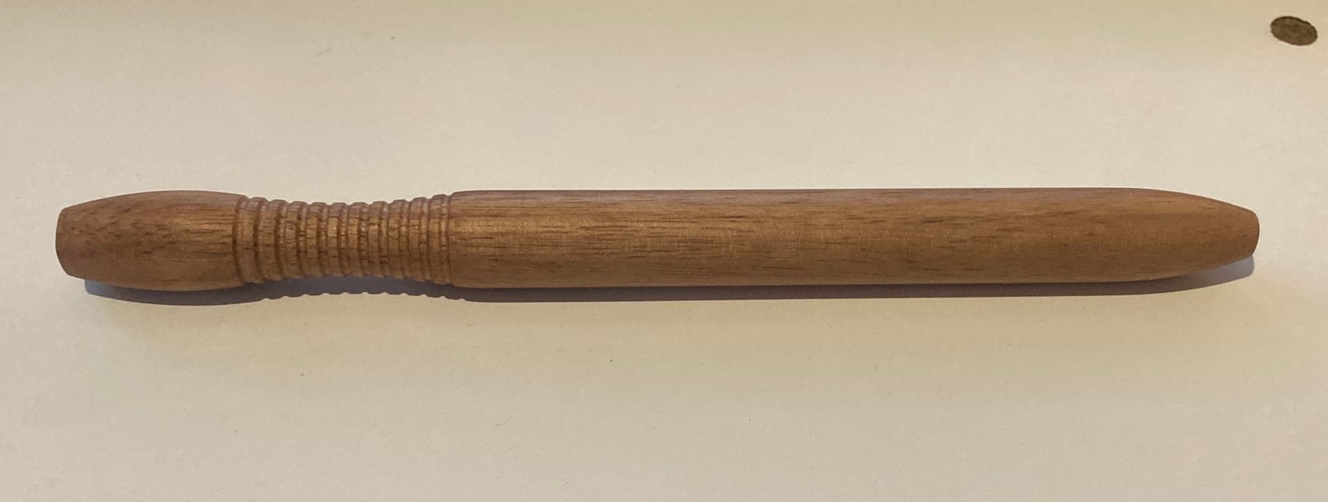
Yes, I know that these are traditionally cut on a lathe. I don’t have a lathe, but I do have a Shapeoko 5 Pro 4x4.
Many trim manufacturers make 3d models and/or svg files of the profiles. So if you find a manufacturer that makes spindles search to see if the 3d model or svg is available and copy that. That will give you a good design to start with. You will likely need CC Pro to do the 3d modeling. I will let others chime in on creating your c3 models.
If you can find a picture on google you can download and use Inkscape to turn the picture into an svg to use as a model to create your balusters.
I did a search for balusters and did not find any databases of images but many trim manufacturers have images and svgs of their profiles. So it will take some research to find the pattern you want or you could draw it up in a paint program and then turn that into an svg.
I have wanted to install a 4th axis on my S5P but the electronics of adding it to the controller escapes me. Anyways, I think about making one with a drill attachment or even a motor attachment that can be switched on manually and then the program ran as a contour program. Maybe I havent thought about all of the dynamics of this kind of setup, but the idea of adding one has been on the mind before.