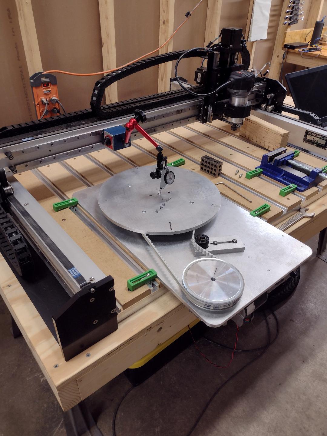
I recently added turntable deck to my Shapeoko Pro XXL, with the goal being to have a set-up where I can create bowl-shaped parts quickly and with a nice finish. In effect, I’m making a CNC lathe, turned on its side.
The idea is to fix my stock to the turntable deck and set it spinning, and then trace a 2D toolpath in the XZ plane (could just as well be the YZ plane) to carve out the profile. Unless I’m missing something, neither my MeshCAM nor my Carbide Create can be used to create the required XZ toolpath. As such, my goal now is to write the required G-code to drive the router in the desired path. I have now taken my first cut at it.
This is my first-ever attempt at G-code, by the way. In my G-code program draft I have the cutter “hogging out” the bulk of the material in five consecutive passes, each time cutting .050 deeper, with a final finish pass that cuts about .020. But I think I have a problem, which is that my code assumes my cutter is zero-diameter, when in fact I intend to use a 3/4" diam ball-end cutter - on the advice of a machinist friend. He mentioned using either a G42 or G43 command to compensate for the cutter diameter. So I added - or tried to add - a G42 code (Tool Compensation Right) to my program. This is where the problem surfaced. When I try to load it into Carbide Motion to drive my Shapeoko I get an error message, which seems to say that G42 & G43 codes are not allowed. Might somebody confirm that? If indeed they are not allowed what might I do as an alternative?
As an experiment I removed the G42 code and reloaded the program into Carbide Motion. The error message went away and the program ran fine, though of course it wouldn’t actually cut my part correctly as it doesn’t account for the ball-end cutter radius. This got me to thinking… how do Carbide Create and MeshCAM deal with it, if the G-code they create can’t have tool compensation? I looked at the G-code from a few of them and indeed didn’t see any G42 or G43 codes. I’m stumped for now and would appreciate any input. I feel like there’s got to be a reasonable way to do this. I really hope it doesn’t mean calculating a bunch of XZ coordinates by hand to enter into the code.
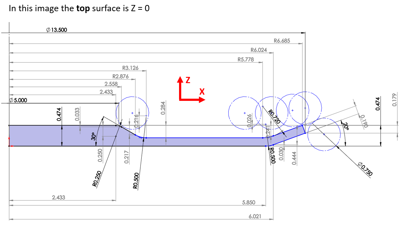
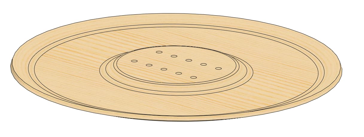
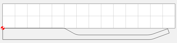
The images at the bottom show the profile I’m trying to cut, as well as a SolidWorks screen shot of the “pizza-pan” part I want to end up with.
Grbl, the firmware which we use doesn’t support this command, save for turning cutter compensation off.
In Carbide Create you can work around this by setting up multiple tools which have different diameters, though for 3D you can change the stock to leave value. MeshCAM has a facility for roughing clearance and so forth.
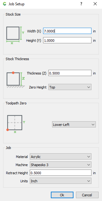
When you zero your tool, type in 0.375 for Z. (zero to the center of the ball)
This is 6 separate contour toolpaths on each of the offset profiles.
Output your G-Code, then just mass edit all of the Y’s to Z’s. Leave the existing Z’s for your retracts. I set my retract distance to 0.5 to make sure it’s above the stock.
gdon_2003 Ha! But you know, I think it would. The motor is a variable speed DC motor (from Makermotor) with a 100 RPM max. My pulley ratio is about 0.6:1, so I can go from a max of about 60 RPM down to about 20 RPM with good stability. The guy at Makermotor (sole proprietor) is very good to deal with, by the way.
Many thanks for the reply and suggestion. I have the feeling I’m making this harder than it needs to be. But I’ve had a hard time wrapping my brain around it. If the cutter were a plain square-end type, i.e. a right cylinder, I could better picture how it would cut, but the ball-end shape is - wait!! I think it just hit me what your idea is! I think you’re saying that rather than writing the G-code myself let the CAM software do the work (in the XY plane), then open the code and manually transpose the Y coordinates it spat out into Z coordinates (using a find & replace-all command to perform a mass edit to change all Y’s to Z’s). Is that right? If so, I follow that. But I don’t follow the bit about “Leave the existing Z’s for your retracts”. It seems like the above process would result in code that consists of a good number of lines of code, most of which will now be of the form something like "G01 X2.60 Z0.05 Z0.50 F40”. In other words, there would be an X coordinate and two Z coordinates, but no Y coordinate, per each line of code. I must be missing something.
I just sat and tried to list the steps required to execute this approach and I keep running into more questions. Forgive me for being dense, but as I mentioned this is my first foray into G-Code, so maybe I haven’t yet learned to think in the required mode. Or maybe I am dense. I’ll list my questions here:
When you say “Output your G-Code”, where am I outputting it from? MeshCAM? Carbide Create?
In what format would I put my desired 2D profile into either of those two CAM systems in the first place? I figure I don’t want to put my whole SolidWorks model in there (saved as an .STL file), because I want the machine to move only in a 2D toolpath (in the XZ plane). Maybe save the profile sketch as a .dxf?
Say I do get my profile into MeshCAM or Carbide Create in the XY plane, how do I get it to generate a toolpath with the 5 or 6 multiple .050” passes? When the CAM asks me for depth of cut, which sets the number of passes, it’s working in Z, not Y.
All right, now I’ve got myself tied in a knot.
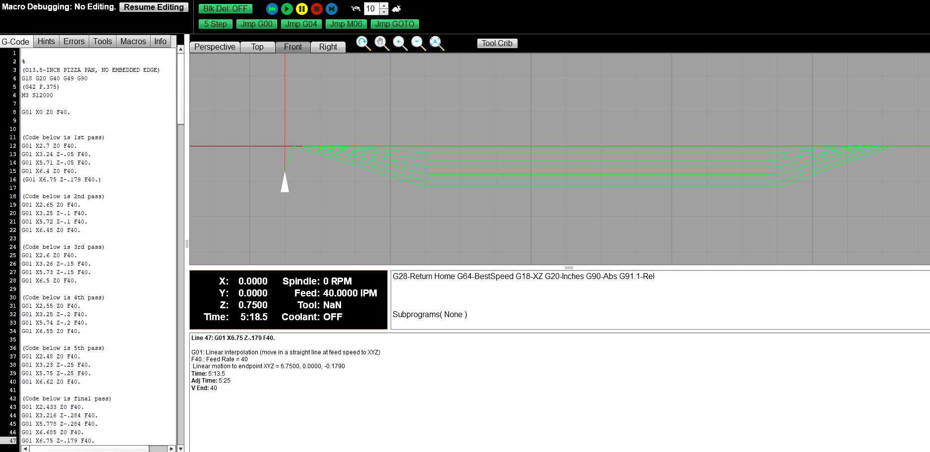
P.S. The new image here is the G-Code file I wrote in G-Wizard Editor. Well, I wrote it as a .txt file and cut & pasted into G-Wizard Editor to see what it looks like. This is the code that presumes a zero-diameter cutter, so it’s not useable as-is.
Okay - so that confirms the G42/G43 codes are not allowed on a Shapeoko. Thanks for the confirmation. But I have to admit I don’t understand how to implement either approach you’ve mentioned here. Are you saying that both Carbide Create and MeshCAM can be made to produce a 2D toolpath in the XZ plane?
There are no blocks with all 3 axes. It’s either just a Z move, or a XY move.
“Output your GCode” = “Save GCode” in CC
Ah, Glad you mentioned depth of cut, Max depth. If we set “Zero Height” in setup to Bottom, and the thickness to 0.625, the retracts should be good.
The first line after the “(PREPOSITION FOR RAPID PLUNGE)” would have to be edited to set the Y at 0
G0X6.4909Y0.5598 → G0X6.4909Y0.0000,
And then all of the other Y’s would become Z’s
I just drew the profile from your drawing. But if there’s a way to get from your CAD system to an SVG you could import it. Solidworks → .DXF/DWG → SVG ??
Process…
Draw the profile of your revolved part with XY 0 being the center and top of your part.
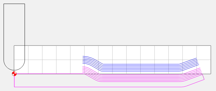
I placed a profile of the cutter at the starting point. Note that the center of the ball is at the starting point of the first cut. This is why you set the initial Z zero to 0.375, and not 0.0
Save GCode, and edit the file.
Change all of the Y’s to Z’s
Change the first move in each path (Preposition Move) Back to Y0.0
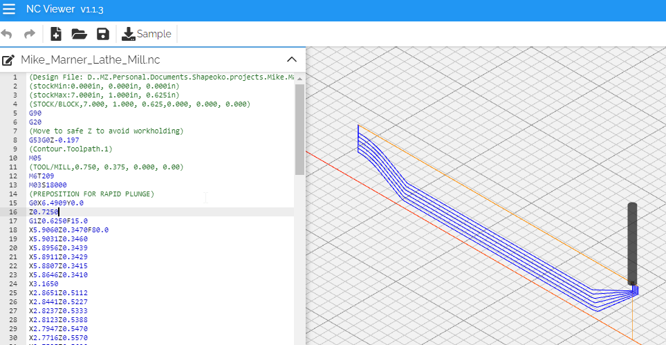
Save the file & verify (This is NCViewer)
Please pardon the delayed reply. Frankly, I’m a little gobsmacked about how much effort you put into this for me. How incredibly cool.
I’ve been away from this for a couple days - distracted by general domestic bliss (and changing the shifter bushings in my old 4Runner) on Sunday and by a full day of work at my “real job” Monday, yesterday. But I didn’t want to let any more time pass, lest you think I don’t appreciate your effort! I’m super anxious to try it out, but alas have another full day of work in front of me before I can get to it.
If you ever find yourself in either Tucson, AZ or Rochester, NY I hope you’ll allow me to buy you a beer or a cup of coffee. I spend time in both places.
I’ll post my results here as I make progress. Thanks again for the help.
No worries, I was distracted by a 30-pack of Stroh’s all weekend. (not to mention a boat, lake, fishing pole, several bands & a golf course)
I’d highly recommend verifying your path (NCViewer.com or similar) before cutting. Easy to fatfinger something.
No trouble really. I started using Unigraphics back in version 4 (circa 1987) when there was no lathe programming. So we had to use tricks like this to get what we wanted.
The key is not to view a CAM software as a 100% solution, but a tool to do the things that would be very difficult manually.
That sounds like sound advice - and an excellent weekend! I was also distracted by a six pack of Pilsner Urquell that my wife bought me as a treat and several bands myself.
It’s funny you mention Stroh’s beer. I hadn’t thought of it in a long time, but just this past week, for a reason I don’t recall, I told my wife about a rumor I’d heard back in the late 80’s/early 90’s that fire departments all over the country switched from the terrible high-visibility yellow-green paint scheme on their trucks back to traditional red because people instinctively recognize big red trucks as important.
The rumor was that someone noticed that while people wouldn’t pull aside for the yellow-green fire trucks they would pull aside for the big red Stroh’s beer trucks. I don’t know for sure if it’s true, but it makes for a good story.
And now back to CNC…
Thanks for the tip about ncviewer, but somebody else had already put me on to that sometime back. It’s amazing that it’s freeware. G-Wizard Editor seems to provide much the same visual simulation. I’ve run them side by side to see how they compare. I just got the G-Wizard Editor recently though. I got a good deal on a lifetime subscription, which is why I decided to pull the trigger. It is supposed to have good conversational CNC programming capabilities and a few other niceties. We shall see.
I still haven’t had time to try your scheme or look at the code you sent, as my day job has had me tied up. I hate it when that happens. So, I think it will have to wait for this long upcoming weekend. I can barely wait to try it. I’ll post my results.
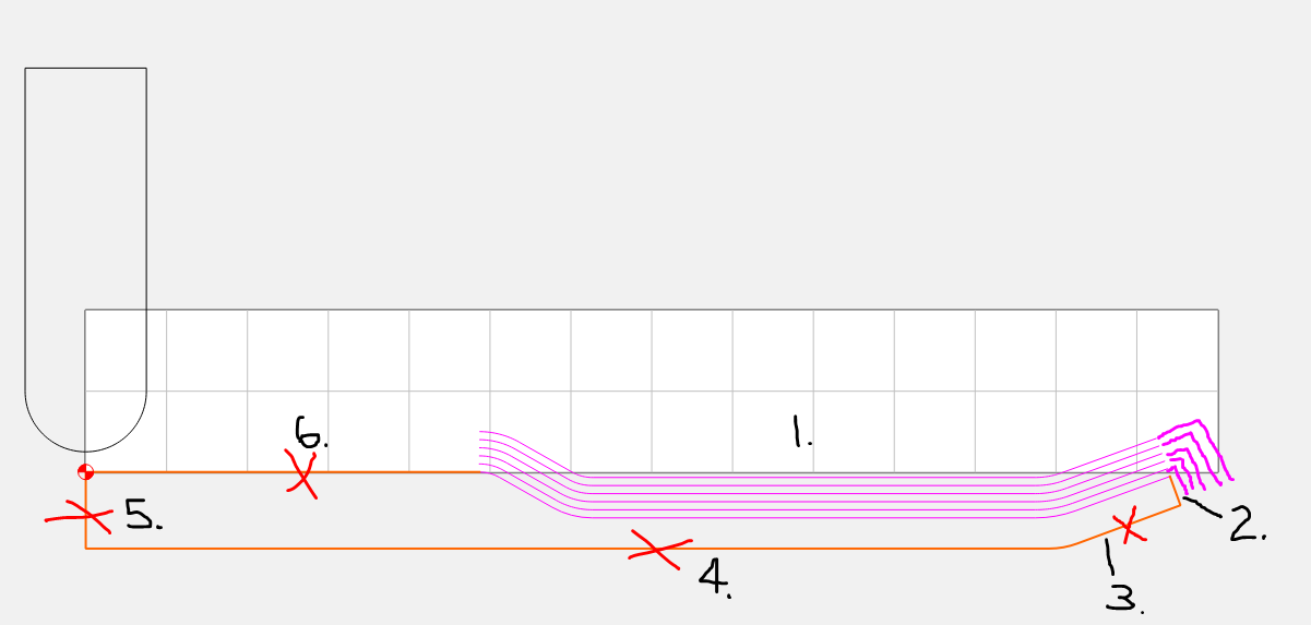
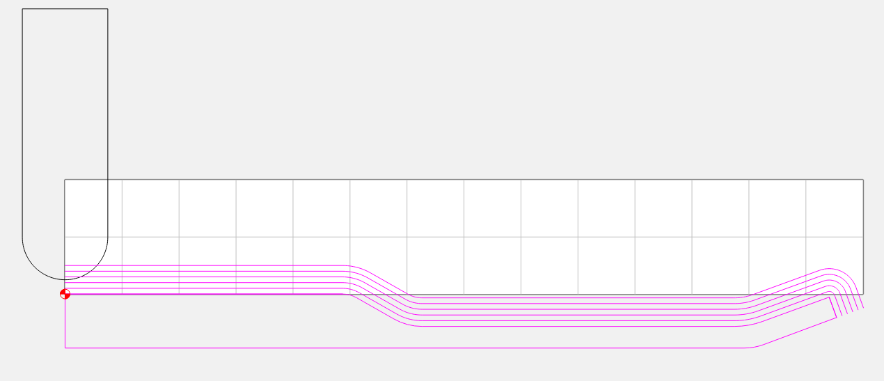
I have made some progress with this project this weekend. Basically, I’ve gotten the code to function the same in ncviewer as your example. The thing is, I need the toolpath to include the little dog-leg at the right end of the profile. See the image below. What has me hung up is that Carbide Create won’t seem to let me edit the vectors. I figured I’d be able to delete everything I show as X’ed-out and just cut the paths I want for now. In particular, I’d like to add segment 2 to the profile you already helped me with (labeled segment 1 in my screenshot). Then I’d delete segments 3, 4, 5, and 6 and create my toolpaths. Then I’d put it on my turntable “lathe-on-its-side” and cut that profile. With that done, I’d take my stock off the turntable deck, flip it over and put it back on, and the do a similar process to cut the bottom profile. That is, I’d cut only segments 3,4,5, & 6, but exclude segments 1 & 2. Does that make sense to you?
Jeez - I butchered that. I typed the last couple lines in haste when I realized I needed to be across town to meet my wife. I wanted to post the question before I called it quits for the day and didn’t take the time to proofread for sensibility.
So, thanks for taking the time to decode it. What you figured is exactly what I intended. To confirm, I’d like to cut the top profile vector, which will consist of segments 2, 1, and 6. Then I’d take my stock off the turntable, flip it over and reinstall it on the turntable, and cut the bottom profile vector, which will consist of segments 3 and 4. Segment 5, as the centerline, would never get cut at all.
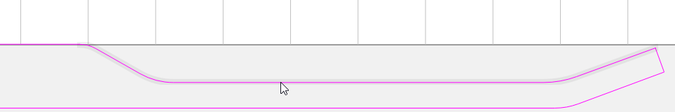
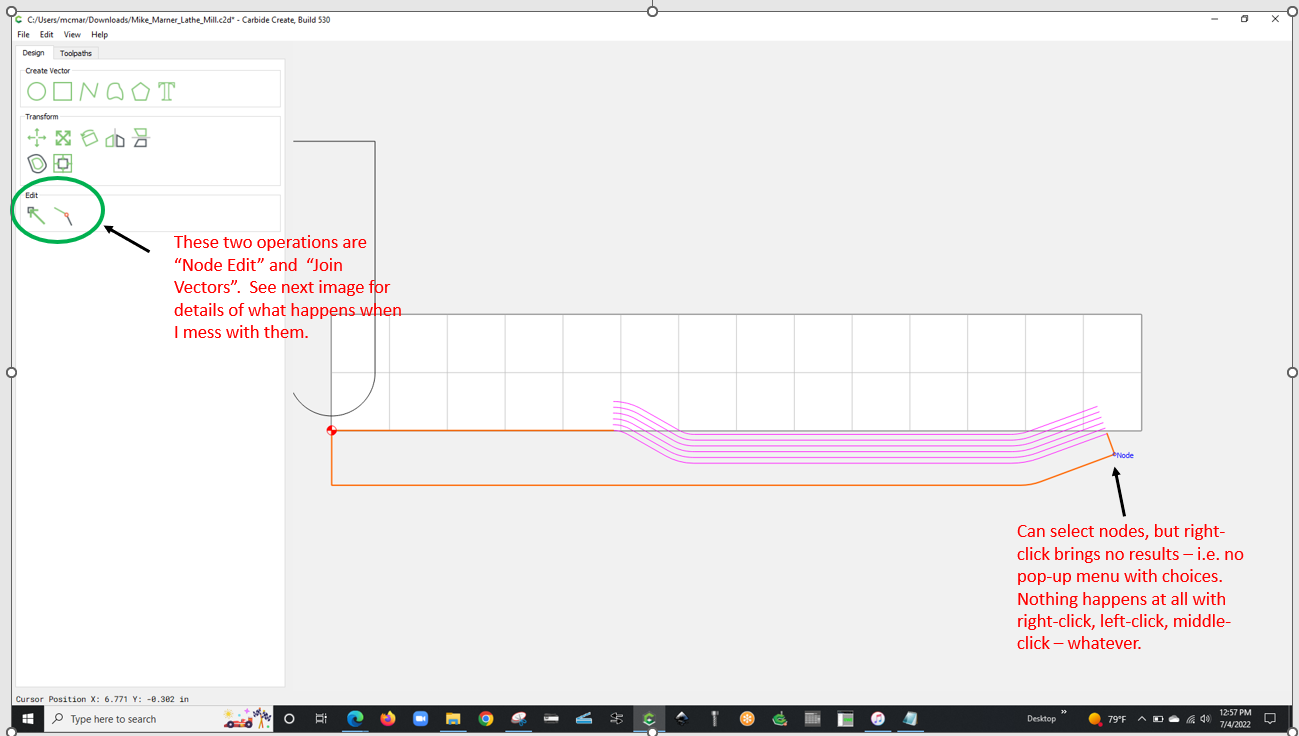
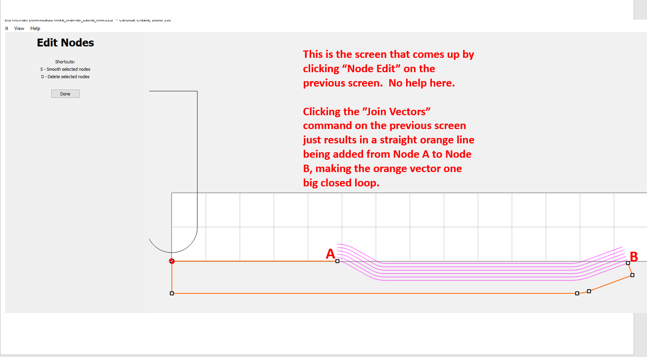
Okay - with that established there remains the issue of editing the vectors. The screenshots below show what I run into when I try to do so. I can’t navigate anywhere to find the command “Cut Vector”, which leads me to question if our software is different. I’m using standard Carbide Create. Might you have Carbide Create Pro?
Okay - I’m getting somewhere…see the new screenshot below.
After striking out with the Cut Vector approach I tried your second suggestion, which was to create a new line using the nodes on 2. Then I did the same with the nodes on 6. After that it took me a while to figure out how to combine segments 6, 1, & 2 into a single vector. I was holding down CTRL to left-click-select them in sequence, as I’m accustomed to using that technique in SolidWorks and Creo and a few other kinds of software, but it wasn’t working. At some point I tried left-click & drag a box to capture them all and it did work. Then I clicked Join Vectors and bang, they combined into one vector. With that done I offset the new vector five times at .050 per instance.
I think I’m gonna try to cut some wood now! Some scrap wood, that is.
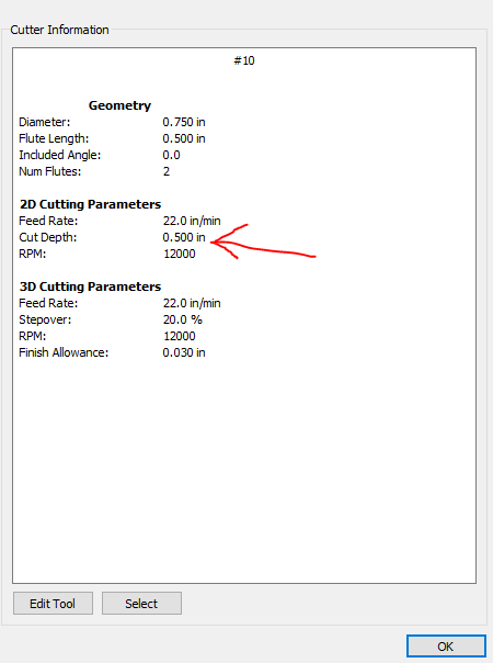
I spoke too soon! When I saved my G-code and went to edit the file I found that it had way too many lines of code. Then when I ran it in ncviewer I saw the problem was that it was cutting each of the six contours 10 times. After a while I realized that was because I had, in my cutter bit set-up parameters, a depth of cut of .050, with a Max Depth of .500. So it wanted to cut 10 x .050 deep passes for each contour to achieve the .500 Max depth.
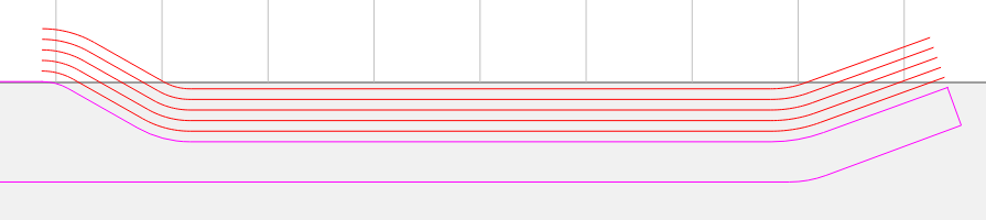
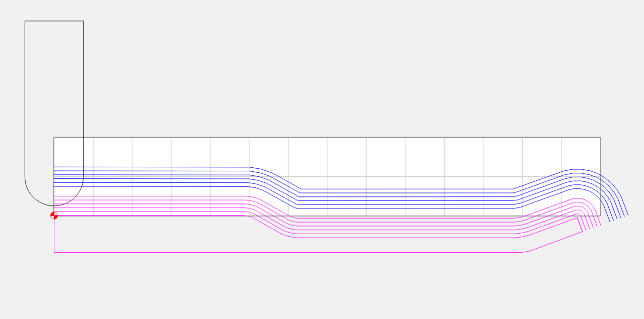
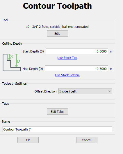
So, I went back into my tool settings and changed the .050 “Cut Depth” parameter to .500", then re-calculated the toolpaths. That indeed changed it to one pass per each contour. Then I tweaked various other lines to address some other weirdness I was seeing in ncviewer, and the current result is shown below. It’s looking pretty good, but I’m still a bit unsure of myself with this.
I’ve screenshot some of the various pop-up windows to show what I have selected. I’d appreciate if you’d look them over and let me know if you see any issues.
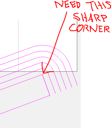
I’m also not sure what to do about the corner at the top of Segment 2. I need it to be a sharp 90-degree corner, not a radiused corner as ncviewer seems to be showing it.
If you draw a 0.375R circle anywhere on the last/lowest blue toolpath, you’ll see that the cutter rolls around a sharp corner.
You are setting your zero to the center of rotation. This is good. When you bring your tool down to touch off your Z zero, touch the top of the stock, then in the Jog screen select Set Zero, and instead of clicking the Set Z Zero button, type 0.375 into the Z field, and hit enter.
Ah, I just pictured a 3/4" diameter circle rolling around that hard corner and now I see what you mean. I guess the innermost blue contour with its rounded corner fooled my eye - fooled my brain, for that matter. Okay, thank you for setting me straight on that. It was plain old geometry and all I had to do was take the time to think about it.
As for the setting the zero height at 375, now I get that too. Thanks likewise for that
No worries. It’s an odd concept when it’s new. It’s typically called “TCP” (Tool Center Point) programming. It’s used on lathes, and some 5-axis contouring machines to allow the operator to rotate the tool without the need to create a new program.
I have customers that are machining full scale cars out of clay or foam using it.