How is "No Offset" measured for a contour?

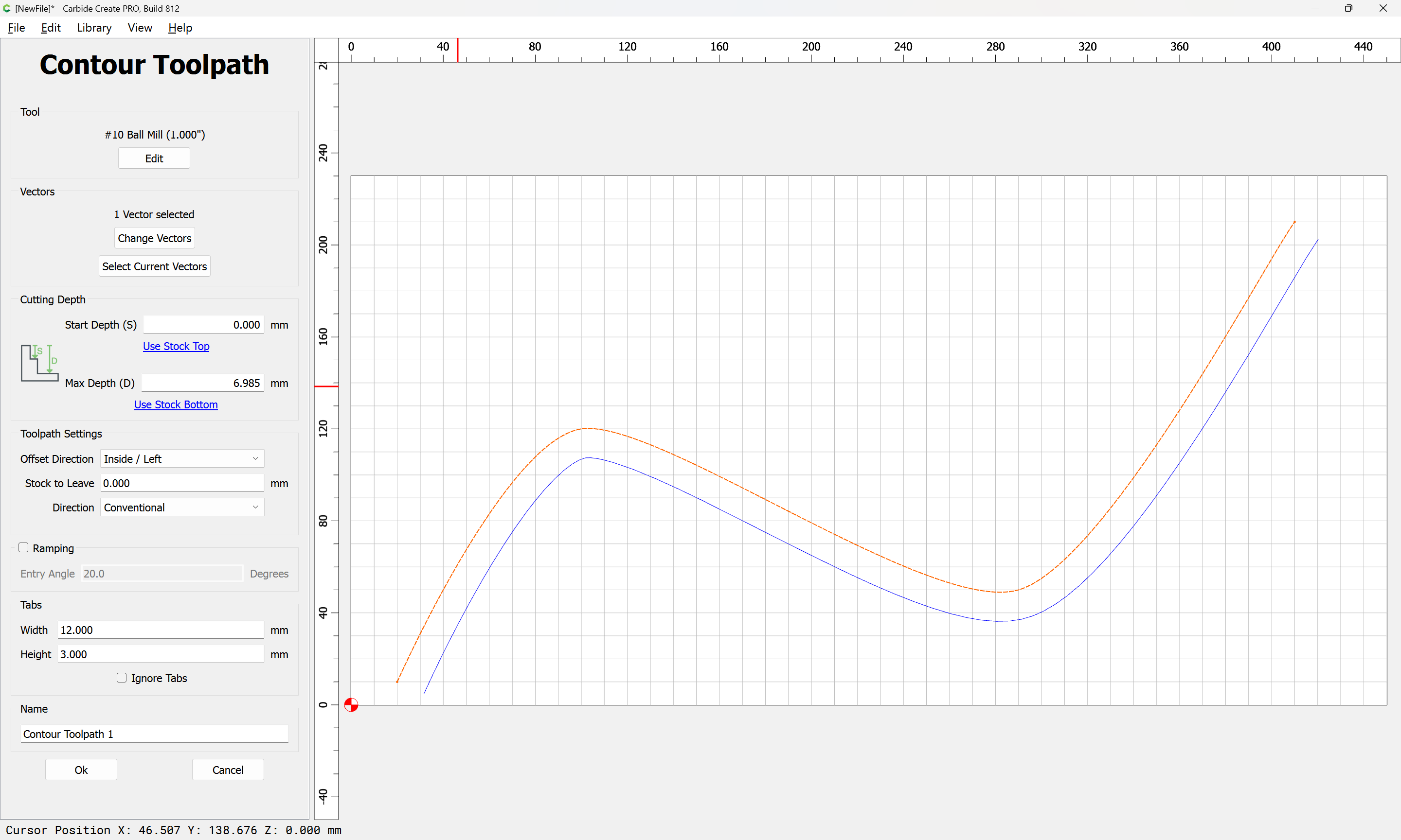
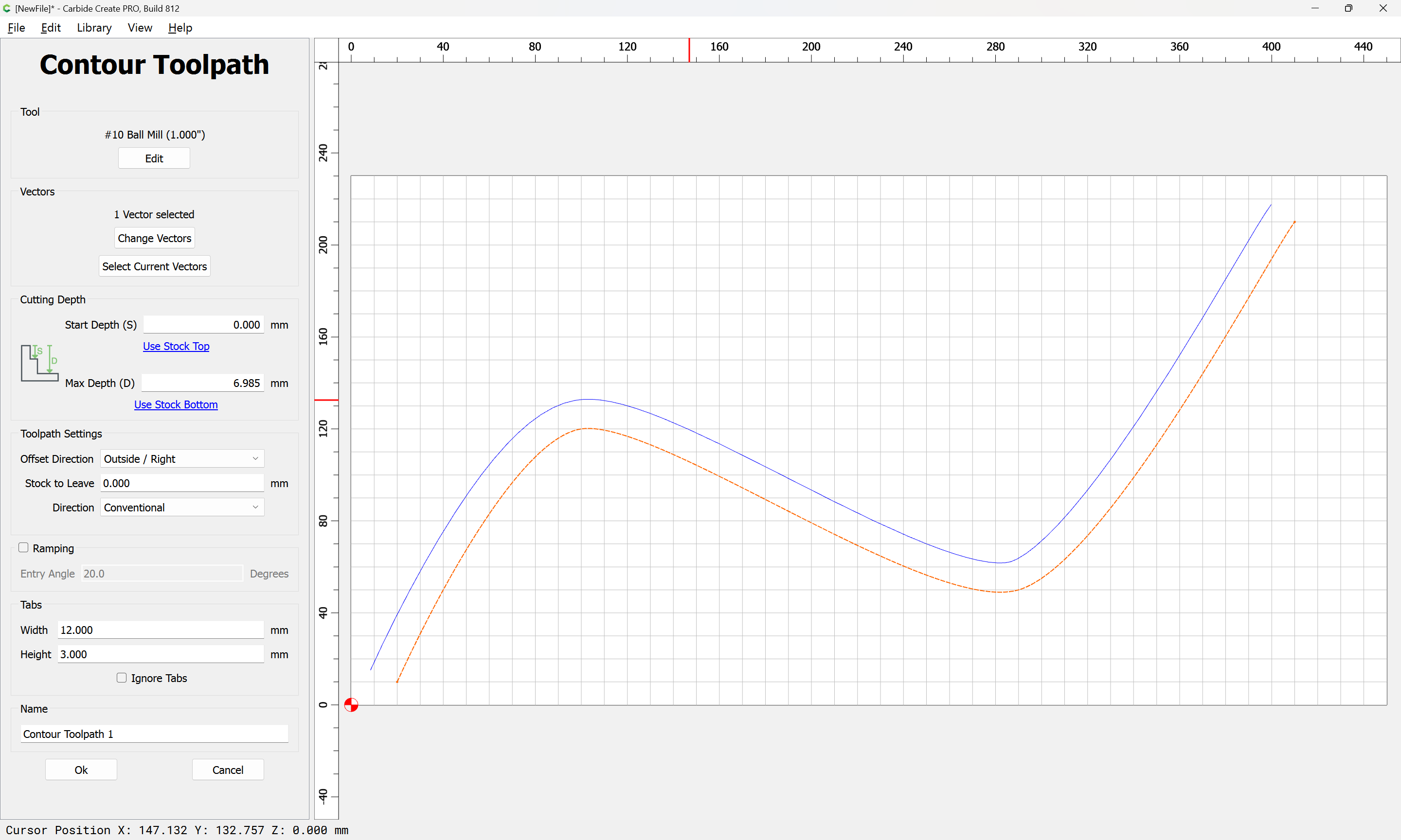
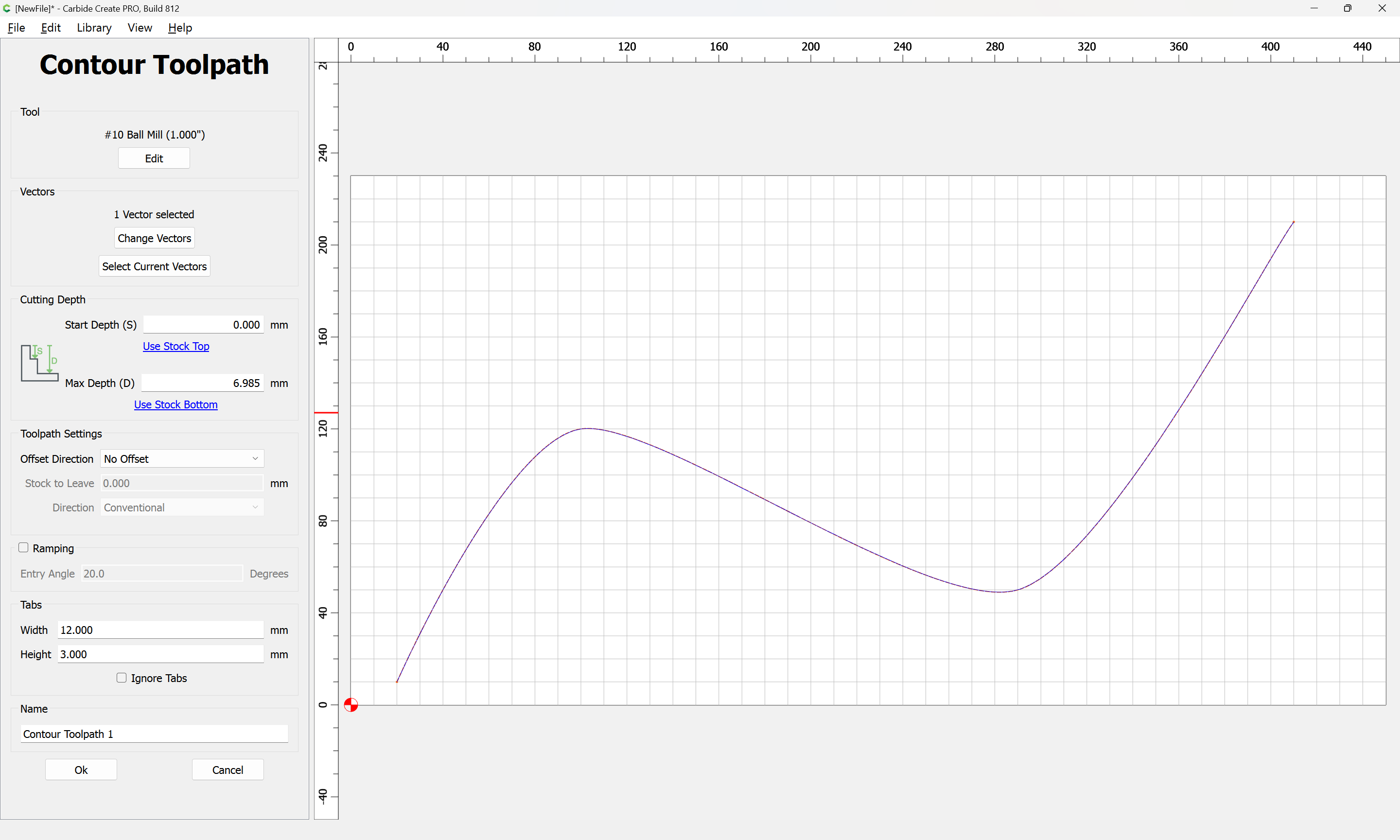
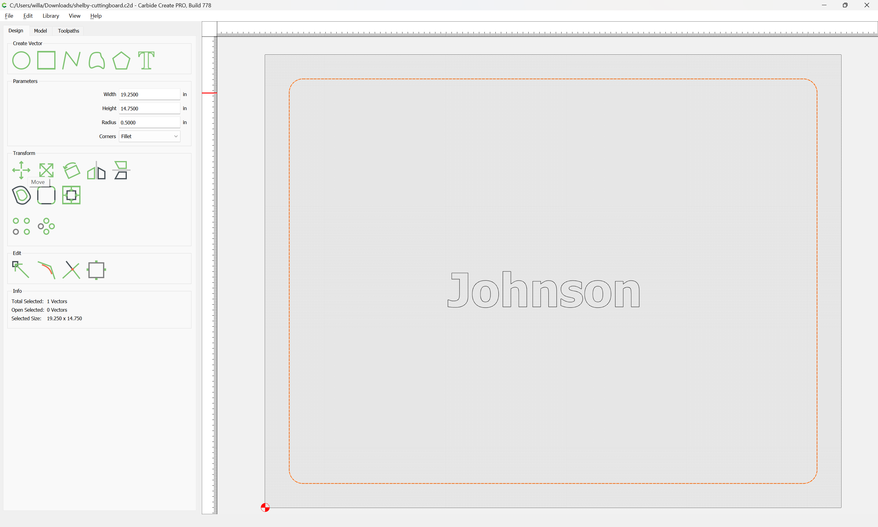
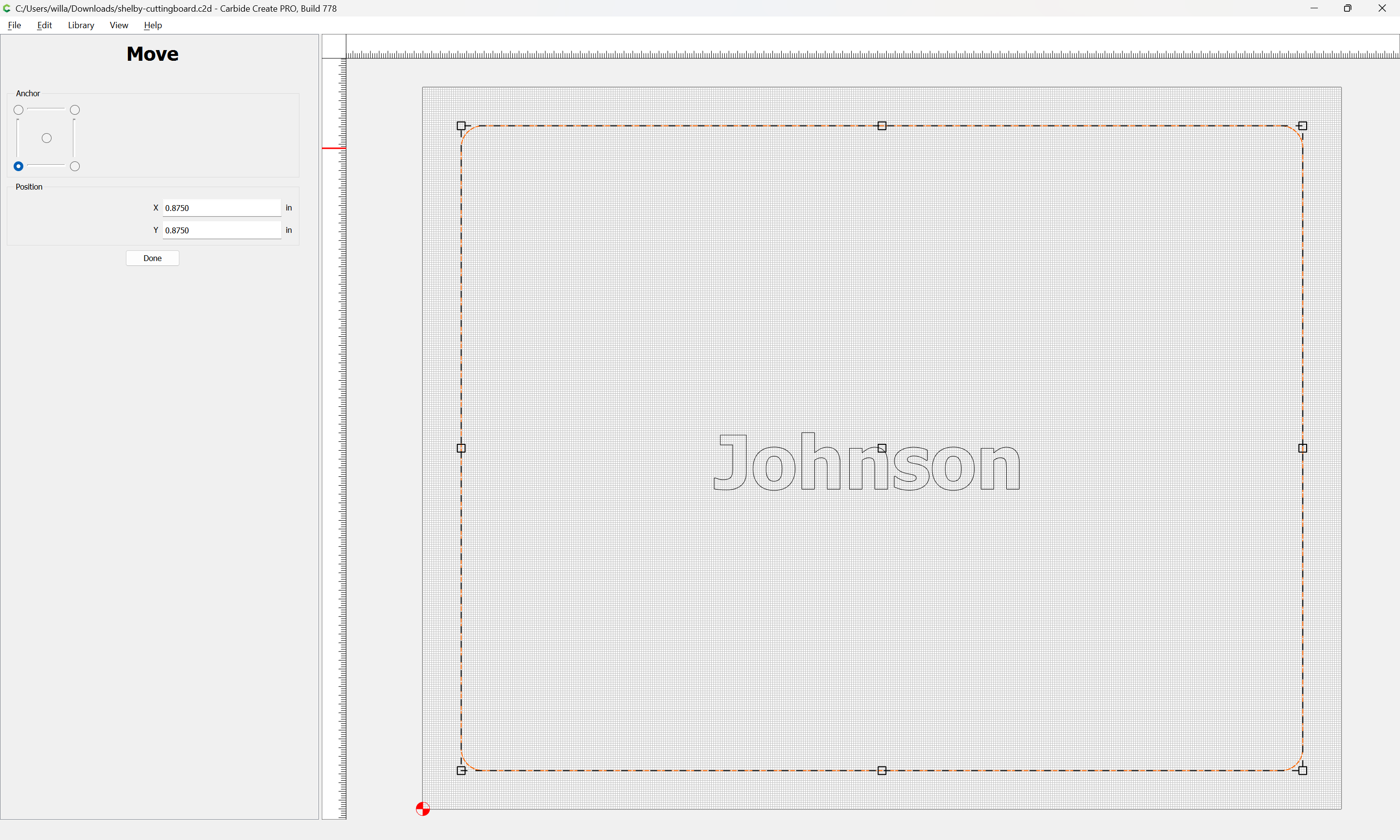
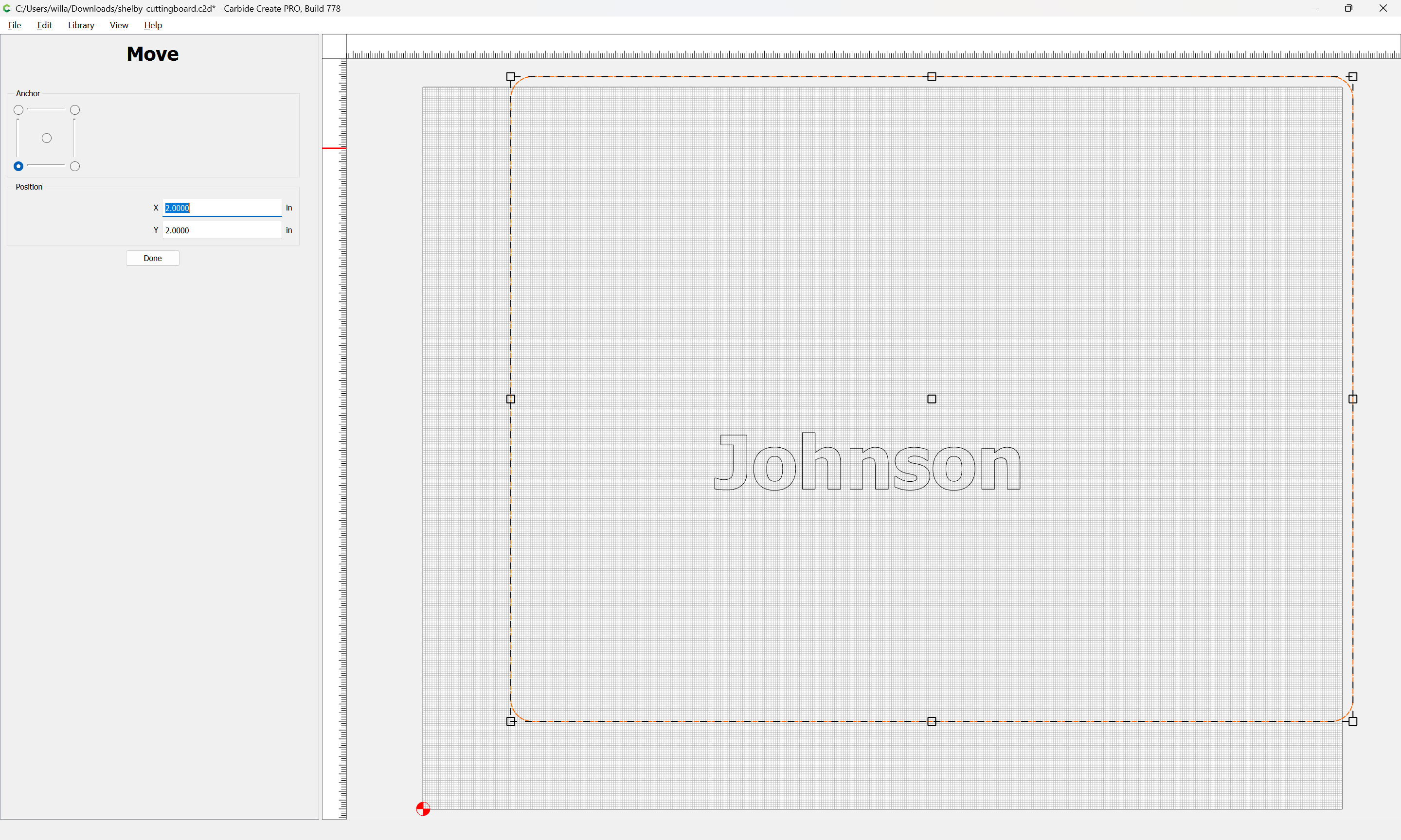
I would expect that it would be dead center of the bit, no matter what size of the bit, but that surely didn’t happen to me with a custom bit.

I used the following 3/4 Bowl and Tray bit and it seemed to use the inside of the bit. I had a square drawn 2" from the edge of my work piece (it was a cutting board doing a juice groove) with a no offset. I was expecting the middle of the bit to be 2" from the edge of the board. So with this bit was expecting it to be at 1.625" and 2.375 but what seemed to happen was the edge of the bit was at 2" middle of the bit was at 1.625 and the other edge at 1.25.

I double checked and I had it set to “no offset”. Is my expectation wrong on how “no offset” is being measure?

Are you using Carbide Create? If so post the C2D file so we can see what’s going on.

1 Like

Should be along the contour:

Inside Left:

Outside Right:

No offset:

I am. Just the groove around the edge of the board. It was 1.75 but same point stands.

shelby-cuttingboard.c2d (202.2 KB)

How much of an offset should it be on the inside/outside? Is this dependent on the inside/outside of the bit? e.g. if I’m using a 1/4 bit flat bottom cutter and set it as “outside” the edge of the bit will ride on the “outside” of the contour?

Am I correct on my assumption that for no offset setting the contour path should be the middle of the bit?

That file should cut/measure from the center of the line:

Post a photo of how it cut, link to the tool in question, and screen grab showing how you defined the tool?

Yeah, thats what I thought. I unfortunately don’t have the board any more :(. I’ll see if I can get a picture of it.

Here is what I have in my tools database .csv file. It won’t let me post that file type.

Bowl & Tray Bit

number,vendor,model,URL,name,type,diameter,cornerradius,flutelength,shaftdiameter,angle,numflutes,stickout,coating,metric,notes,machine,material,plungerate,feedrate,rpm,depth,cutpower,finishallowance,3dstepover,3dfeedrate,3drpm
1372,Whiteside,1372,“Bowl and Tray Bit 1/4-Inch Radius, 3/4-Inch Cutting Diameter and 5/8-Inch Cutting Length”,ball,0.75,0.21875,0.625,0,0,2,1.5,0,2.5,40,12000,0.03,0.1,20,40,12000

That was a v6 file:

a

Update to v7 or v8:

and let us know if you have this difficulty in a supported version.

hmmm, it shows I’m on a v7 build.

The file you posted was written out as a v6 file.

How are you checking the version of the file?

Here is the path of the file. It is the same file I attached here.

I opened the file I sent you and did a “save as…” and wrote it out as a new file below “shelby-cuttingboard-testv7-save.c2d”. What does that one show up as?

shelby-cuttingboard-testv7-save.c2d (96 KB)

Opening it in a text editor:

a v7 file shows differently:

t

and the two differing versions have markedly different file sizes:

Interesting…that is super weird…I’ve had v7 installed for awhile now…I started this project like 4 or 5 days ago…no clue how it would have become a v6 file.

Regardless though, I see an option to save as a v6 file in the menu and wonder if that was accidentally hit? Would that cause this issue though?

…I found the issue…

So my board size is 21wide x 16.5high. Job size was set to the same value which is correct…
image

Where I messed up my calculation is in the square inner vector size…I set it to be 19.25" thinking it would be 1.75" from the EDGE of the board…but that value is the total width of the square vector…which means that it is 1.75"/2 as its measured from the center of the board in either direction…so that square vector is really .875" from either edge. So that makes sense on how it was closer to the edge than I really though it was going to be.

Is there a good way to set a vector X inches away from an edge?

Select the object:

Select “Move”:

Move it the desired distance from the lower left corner:

This topic was automatically closed after 30 days. New replies are no longer allowed.