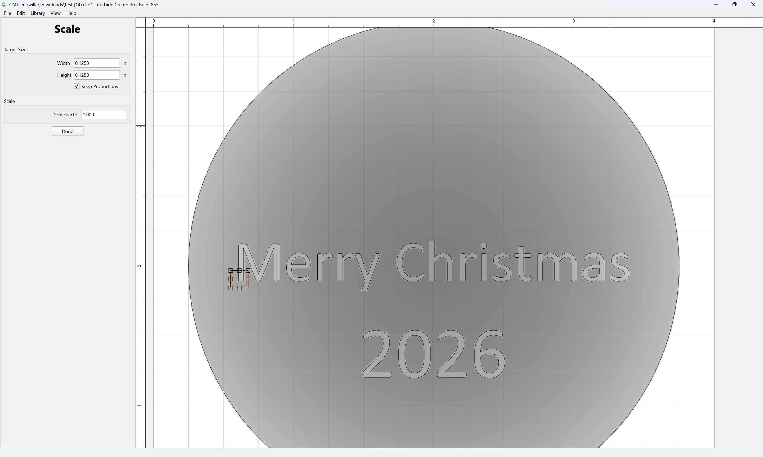
I’ve look at some of the other posts similar to what I’m trying to do but I’m still having trouble. I’m using Carbide Create 853 to try to carve text on a domed/curved surface to be used as Christmas ornaments. When I look at the 3D preview in the modeling area, it looks ok but when I add the 3D toolpaths and look at the simulation, the text is barely visible and not very detailed. I’ve attached the file I’m working with along with an image that I found that shows an example of what I would like mine to look like though it has different words and a heart which I don’t want.
I’m new to CNC carving (obviously) and would appreciate any help you’d be kind enough to offer. Thanks in advance!
So, it looks ok when viewed in the model area but when viewing the simulation in the toolpath area it looks terrible and is barely visible. I haven’t tried to carve it yet because of how bad it looks in the simulation.
Thanks, that does look better but the text still isn’t as crisp as I was hoping. Is it possible to carve the text, not as a 3D shape but the same as I would on a flat surface, meaning the 3D shape (curved surface) of the ornament would be cut first and then the text would be cut next in it’s own toolpath? I’m guessing it’s not possible but thought I’d ask. I think I’ve seen the functionality in vcarve but I don’t want to spend that much money just to make a few ornaments. Thanks again for your assistance.
The 3D modeling should allow quite good fidelity — check the Model Resolution and adjust that and the tool stepover until you arrive at a result which suits.
You have the right idea cutting the lettering as a separate 3D toolpath with a smaller tool.
Try a 1/32" or 0.5mm (0.020") ball, with a pretty small stepover 0.002" - 0.003".
Ideally a 2D path like a pocket, contour or V-carve projected onto the 3D surface would give the best results. CC doesn’t do that, so you are limited to a zig-zag / raster toolpath.
I would change model elements and remove the base height from the subtracted letters, so it’s only the 45° angle cut into the 3D surface.
Also, use ball mills for the finish 3D paths, rather than flat end mills.
There is still some scalloping on the edges of the letters. Nothing to do about that unless you want to do separate 3D paths that follow the angle of each letter section. Still not ideal for rounded letters.
I think offering a profile or follow-part cut pattern in 3D would help a lot.
My recent suggestion to Rob on that is “Toolpath Sub-Groups” which would have the characteristic of disabling “Start Depth” and each toolpath in a sub-group would use as its start depth the bottom of all previous toolpaths, and “Max Depth” would become “Relative Depth” and would cut from the surface of the remaining material down that additional distance.
I also asked (begged) for “fluting” toolpaths which will angle down from Start Depth to Max Depth and have a checkbox for “Reverse Direction”…
Other than that and fixing all the bad clipart graphics, adding a “Stagger” option to Linear Arrays, making it possible to draw Stars using the Polygon tool, and adding an option for making geometry to match toolpath shapes (maybe add a “Trace Toolpath Outline” entry to the righ-click menu?) and touching up the UI in a few ways/places and adding a feature to “Check Cutter Access” where one could click and modify toolpaths interactively, I think I’d be good…