very much a newbie here. i would like to build a bullet caddy for reloading. i know how to make the holes and copy for the number of holes that i need. what I can’t figure out is how to quickly space the holes without having to manually do it. i want 5 holes down and 10 across. anyone have an idea how to do this in CC?
Unfortunately, Carbide Create doesn’t have step-and-repeat or distribute spacing or any features which would make this simple and automatic.
You can use the Align commands, but you need a row and a column of items properly spaced to start — easiest thing is to draw one column, dupe it, rotate it, drag it into alignment, dupe again, drag the duplicate over, then dupe the first column and drag it into alignment, repeating as many times as desired.
Here, assume one wants 1/2" diameter circles on 1" spacing:
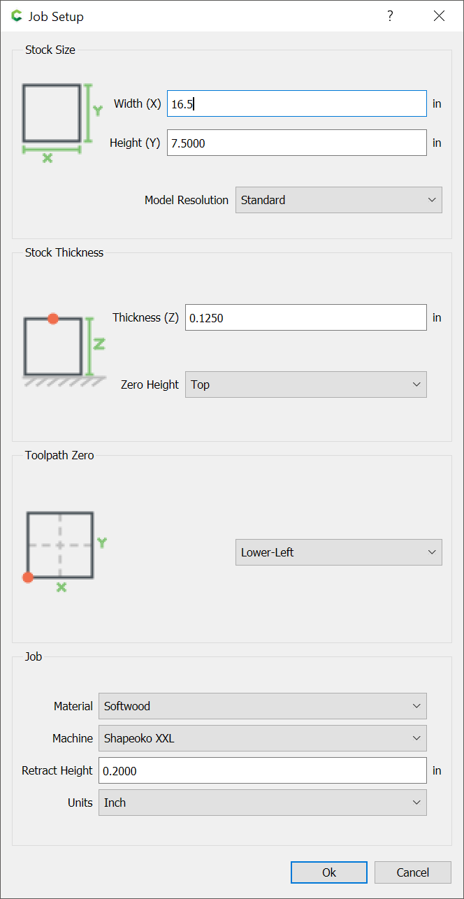
First, set up the document the correct size:
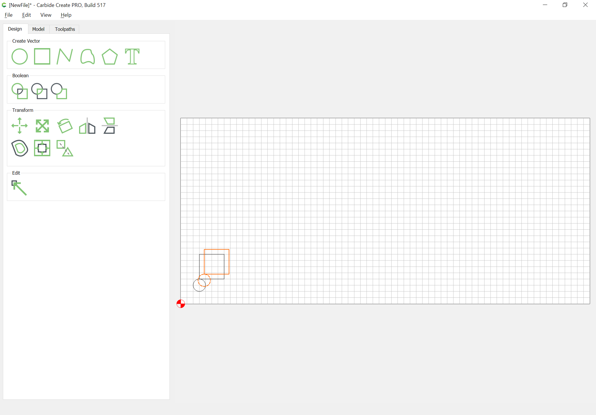
Then draw a circle:

Then draw an object for the spacing:

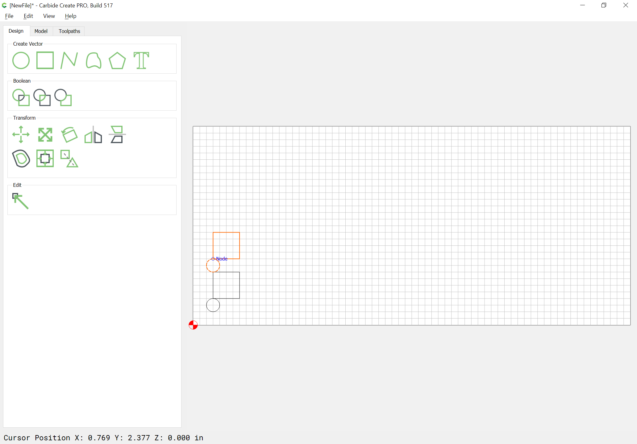
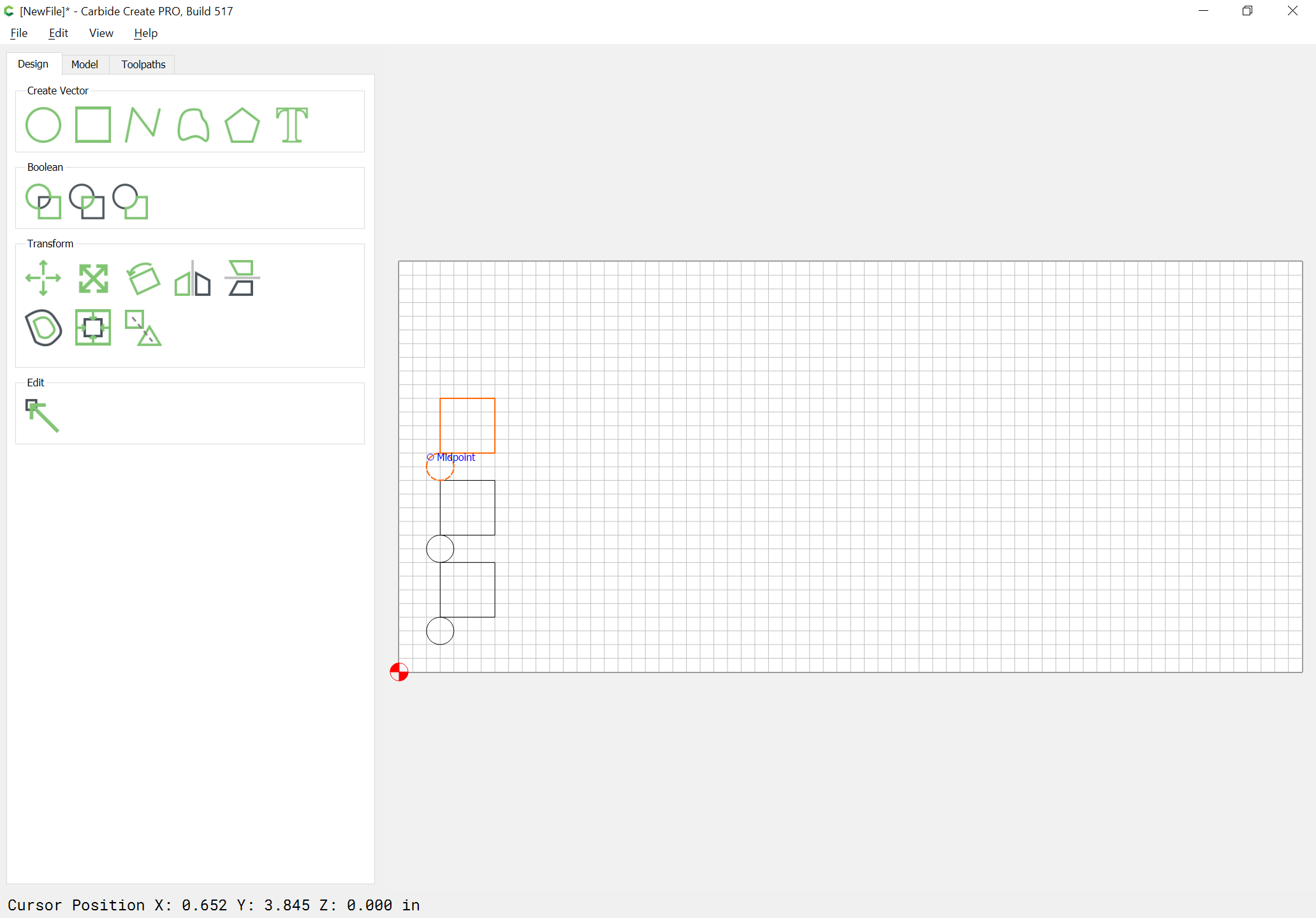
Then duplicate and drag and duplicate until one has a complete column:
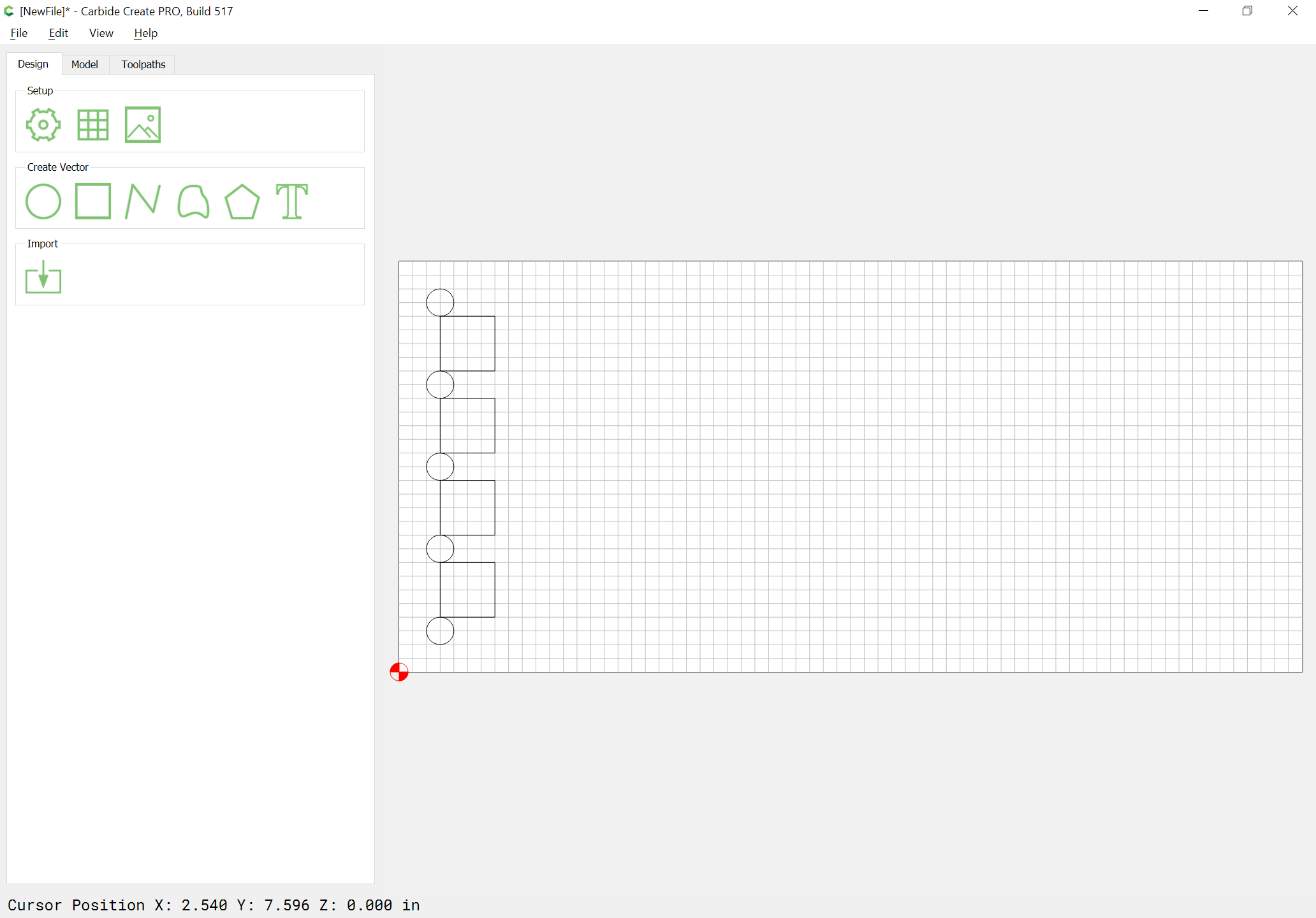
Then select the column of circles:
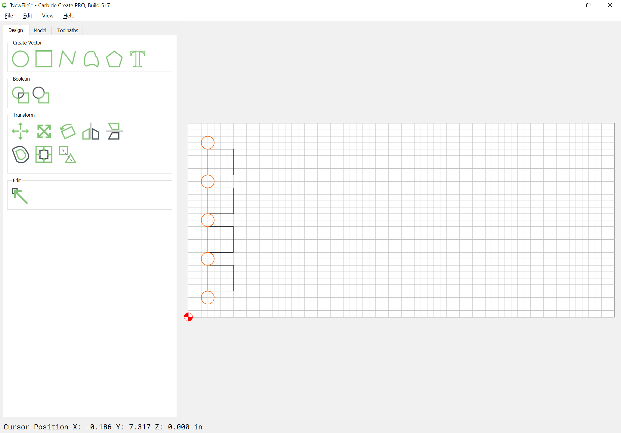
Duplicate it:
Rotate 90 degrees:

Apply | Done:

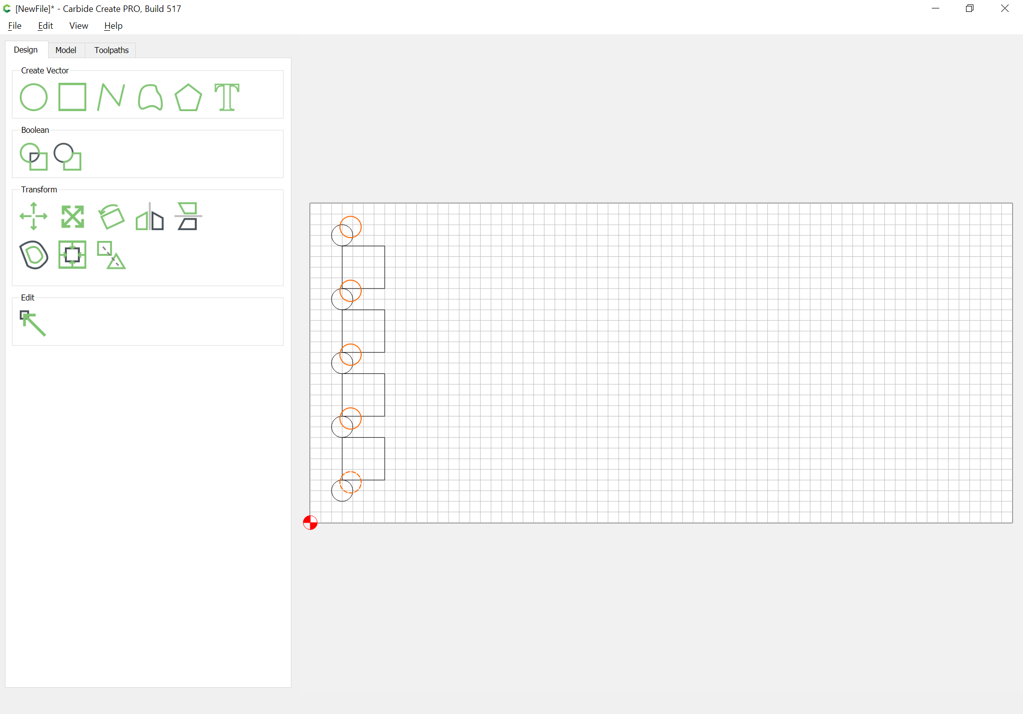
Drag into position:
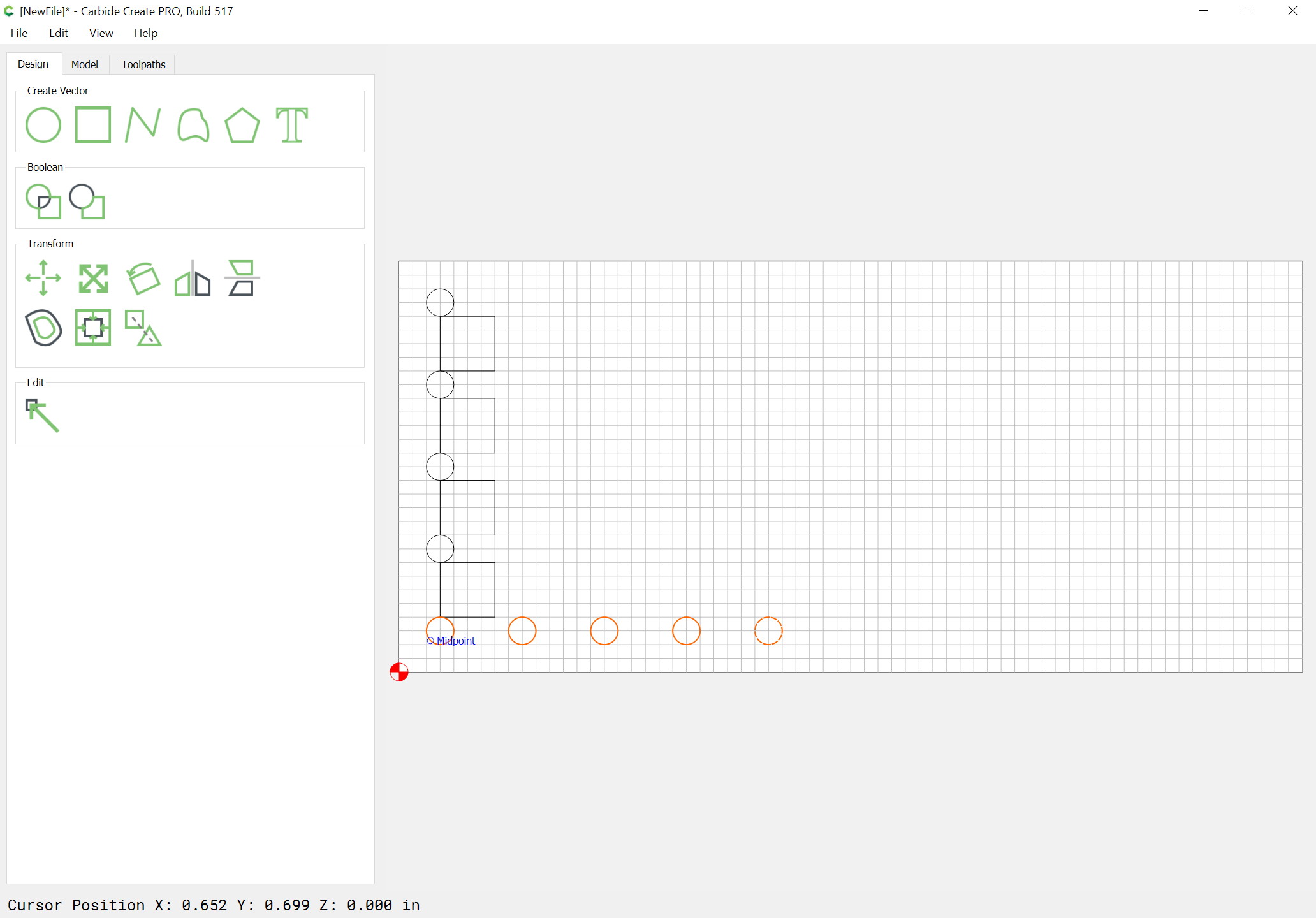
Duplicate, drag duplicate into position and repeat until one has enough:
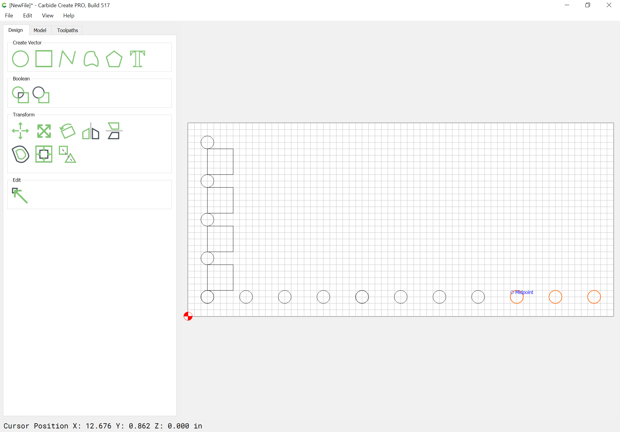
Delete the duplicate and unnecessary circles:
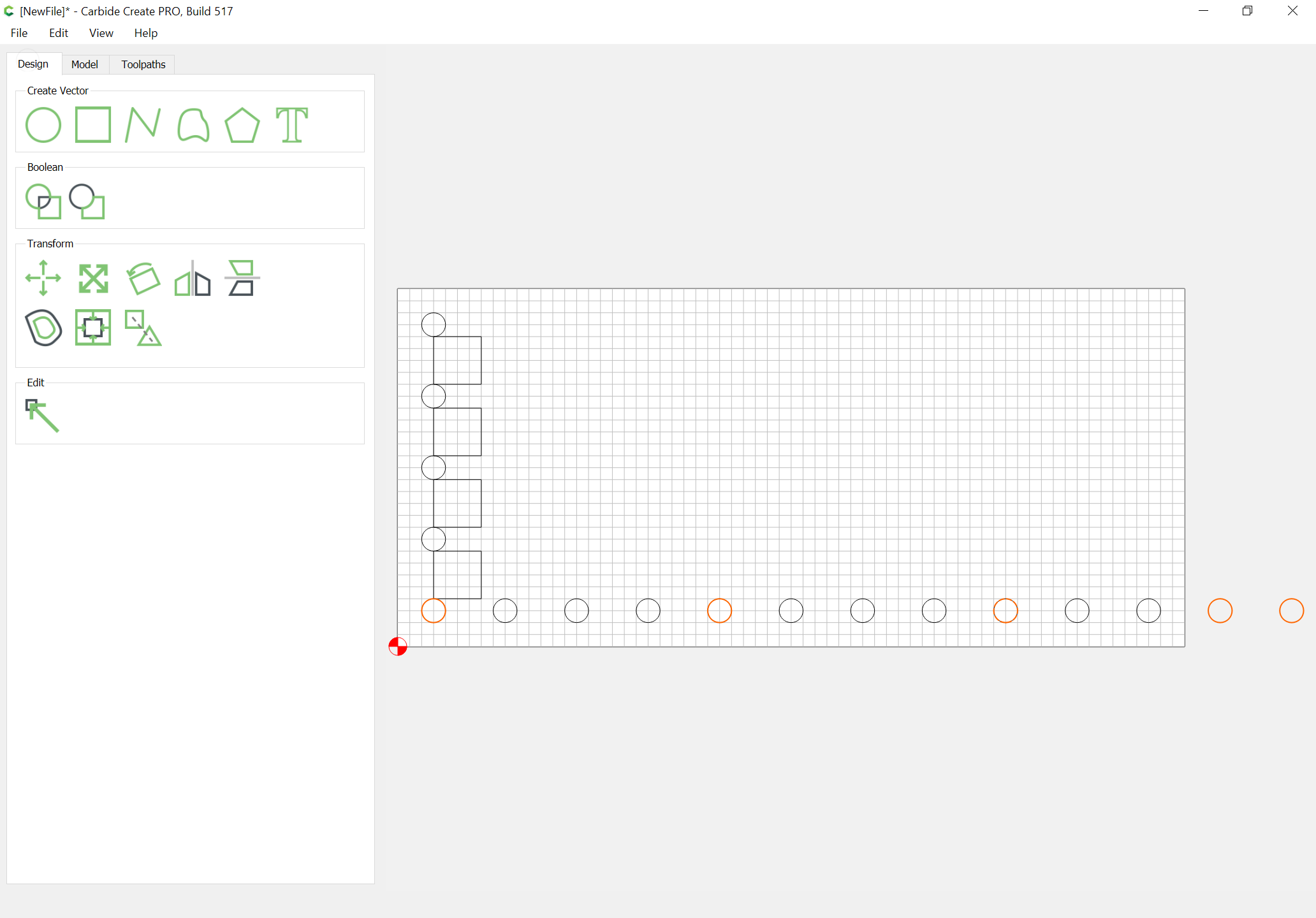
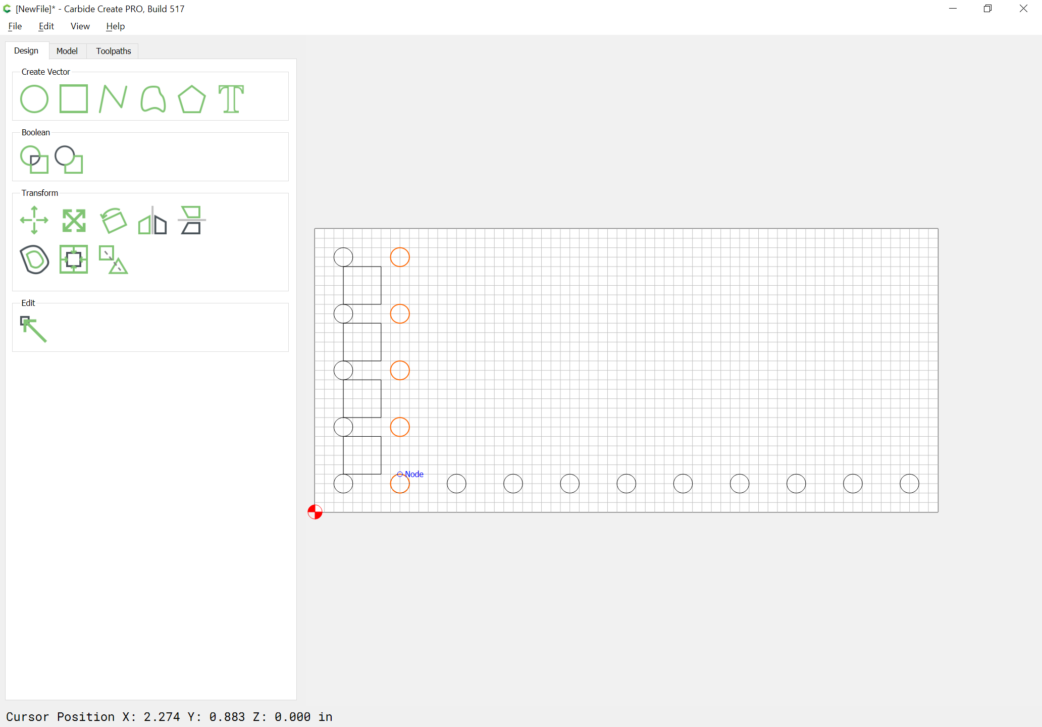
Select the column and duplicate:

Drag into position:
Repeat until all are done:
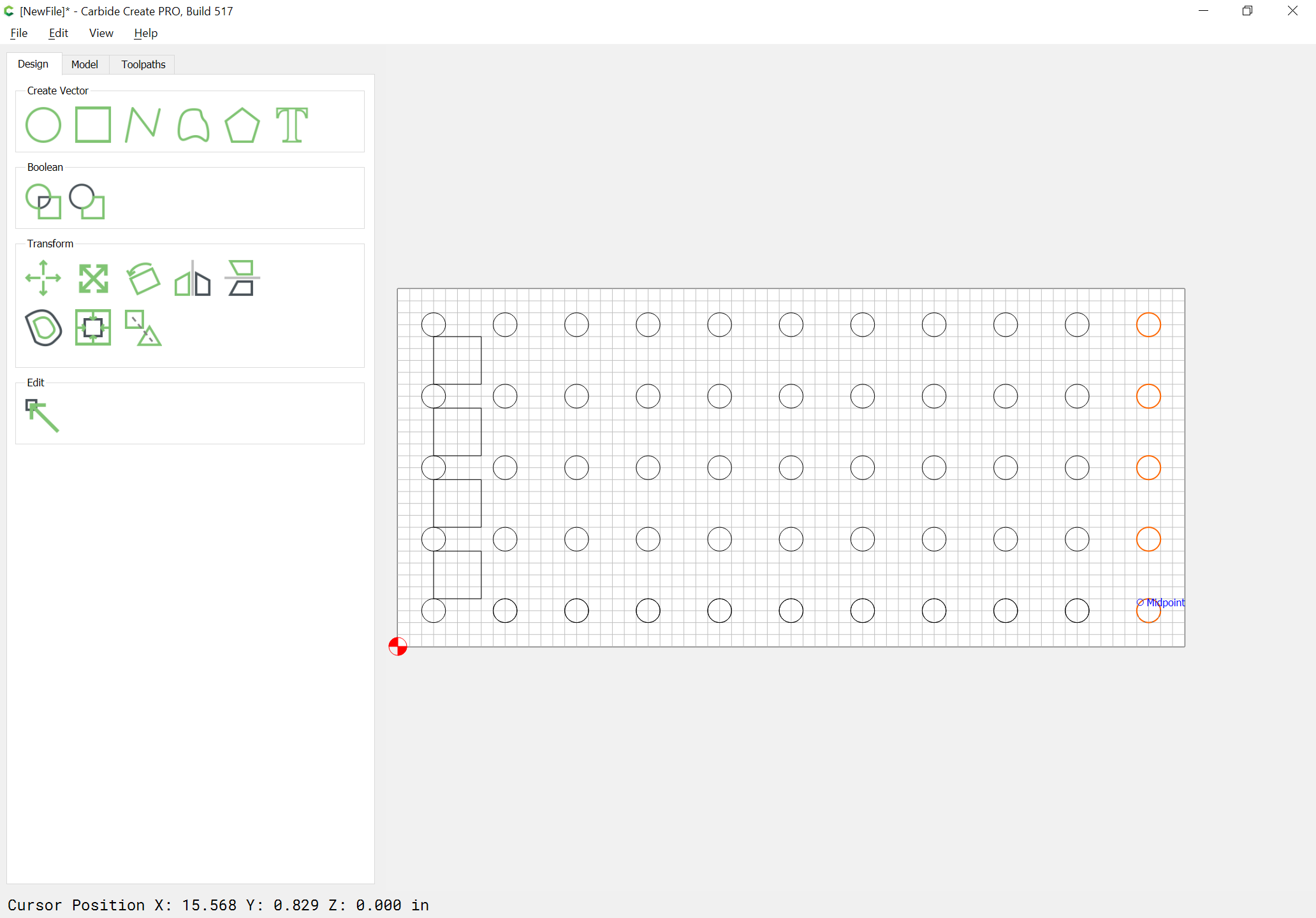
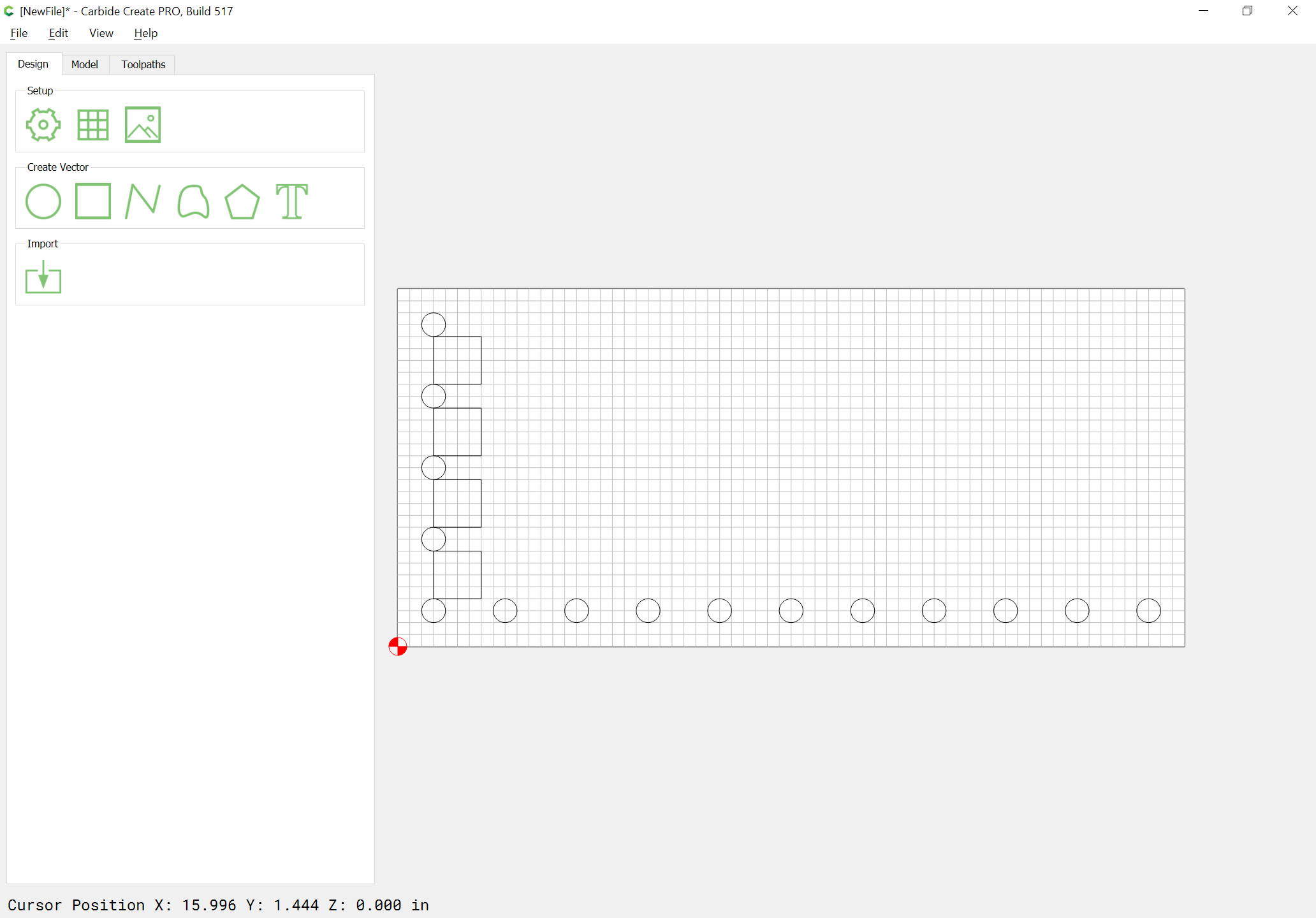
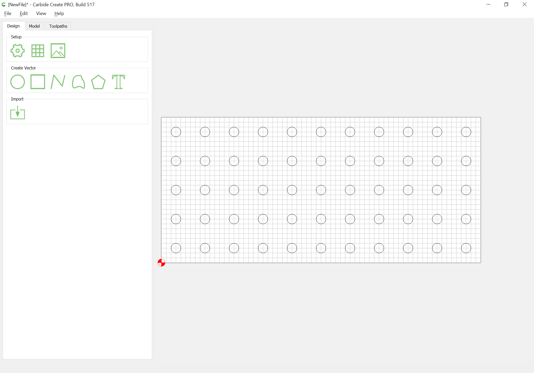
Delete the spacing geometry and the duplicate circles in the lowest row:

Arriving at:
Or, just draw and position things based on their matching up with the grid.
2 Likes
Will Adams always give through answers. For me I just make the first hole the correct size. Then I copy it as many times as needed for a single row. Then I select the whole row and copy as many rows as i Need. Then select all the holes, group them and create a tool path to cut them. I set my grid size to the spacing I want for the holes and while dragging the copied rows I make sure I select the center node and have snap to grid on. This makes my rows line up on the grid for uniform spacing.
4 Likes
WOW, that seems like a bunch of steps for what should be a simple process. i wonder if CC pro has a feature like this?
Wish it was easier. Maybe they will include in future updates if enough folks ask about it
No, Carbide Create Pro does not have any features other than adding 3D modeling.
Step and repeat and object arrays are a frequent feature request, so hopefully that will make its way into a future update once the UI changes from v4 to v5 settle down.
2 Likes
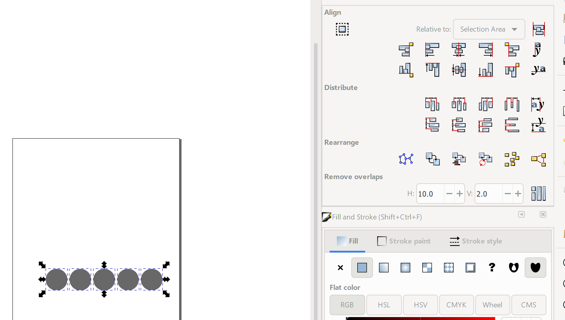
@MattM26 Look into Inkscape. It’s free and provides alignment and distribution functions that will easily allow you to do what you want. Then export the design as an SVG and import into CC to apply the rest of your work. A combination of these functions (align, distribute, and Remove Overlap) will give you complete control - for free - and without any Rube Goldberg-esque manipulations!
1 Like
@jepho No apology needed…
Yes…there is a need to understand Inkscape
And that’s one of my pet peeves about CC - in that, going to another product is usually the answer to a problem. But…for free software, it’s terrific.
The issue for Carbide, of course, will be when CC Pro starts to charge and people are weighing the quality of the code and documentation against purchasing options. Even at a substantially lower cost, if you can’t do what you need to do, that another product does out of the box, without hours of trial and error - or painfully repetitive / contrived tasks, it won’t be worth it. At some point, your time is worth more than the savings. JMO.
All that said, Inkscape is relatively simple to use and if @MattM26 contacts me, I’d be happy to walk him through the process in Inkscape…and I’m no Inkscape expert.
EDIT: Also, I happen to use Lightburn for my laser attachment…and that piece of software, at $40 a license, is powerful, flexible, and intuitive - and supports object matrices as well as all of the distribution functions. I use it all the time as a starting point for my CC designs…but I wanted to answer @MattM26 in a way that doesn’t cost anything.
1 Like
Awesome, Thanks. Ill check it out. when I get stuck, I be sure to give you a shout Gary. I appreciate the offer.
Since people are mentioning other software, it should be noted that Fusion 360 provides this feature standard even in the free hobby version. You draw an object, then click the circular/rectangular/on-a-path Pattern button and tell it how many you want in the x and y direction and the spacing you want. If you go back and change the size of one object, it changes them all.
2 Likes
My intent was not to start a software comparison thread but to just point out that there is an application that has that feature natively available since that directly addresses the question that was originally asked.
1 Like
@jepho Probing, as we do it, is an action that is independent of your CAM choice.
The WCS probing in Fusion would be for probing routines that are not handled by the sender UI. I don’t think anyone here uses them.
To @chilinski’s point (or @GJM’s), drawing can happen outside of Create and be imported for toolpath generation. One should be able to import patterned elements into Create (no clones, though).
2 Likes
For the super-nerdy among us who like to find over-engineered solutions to simple tasks, there is also the possibility to programmatically generate a CC design file that has a predefined array of circles, since CC design files are just JSON text files.
A few pages of Python script does the trick, like in this awful awful hack I experimented with a while back, to not have to manually create hundreds of shapes (and toolpaths!) manually:
I have a feeling that if you asked @fenrus nicely, he would do his magic and come up with one of his online tools where you click-click-click in a web form and bam, a CC file with an array of holes would come into existence.
2 Likes
Some of the terms are probably causing confusion here.
It’s a bit of a stretch to call CM or CNCjs a piece of CAM (Computer Aided Modelling/Manufacturing) software. They are just GCODE senders and not really a CAM since they don’t translate a model into GCODE. That part is done by Carbide Create and Fusion etc.
edit: typo
1 Like
I wrote Carbide Motion instead of Carbide Create… early morning typo. 
2 Likes
interestingly, carbide motion creates motion 
2 Likes
That’s right! Carbide create creates code carbide motion consumes creating motion!
But… back on topic… if you are familiar with javascript, you can do this sort of thing (I hastily adapted a jsfiddle for an SVG library) and save the SVG element:
https://jsfiddle.net/n5h4u0fz/10/
It would be nicer of course to have a site like this but for 2D thingies: Cone (truncated) ✂ Templatemaker ︎
2 Likes
Pretty cool, and a good answer to the original question I think!
1 Like
Carbide Motion is not really CAM, and you don’t ever have any CAM connected to your Shapeoko… that’s basically the clarification
2 Likes
I think the point was that automatic tool change and probing is not due to the specific combination of CC/CM and is readily available in other CAM and GCODE sender options.
For the beginner, you seem to be declaring that all beginners want to pay nothing for software even though they’ve just spent a substantial amount to buy a machine. This is a likely stance, but not the only stance. So building up an argument based on “it must be free for the entry level” establishes a precondition you have decided upon but is not universal. If you scrap that precondition, then the “automatic tool changes and probing early on” has many ways of coming about.
1 Like