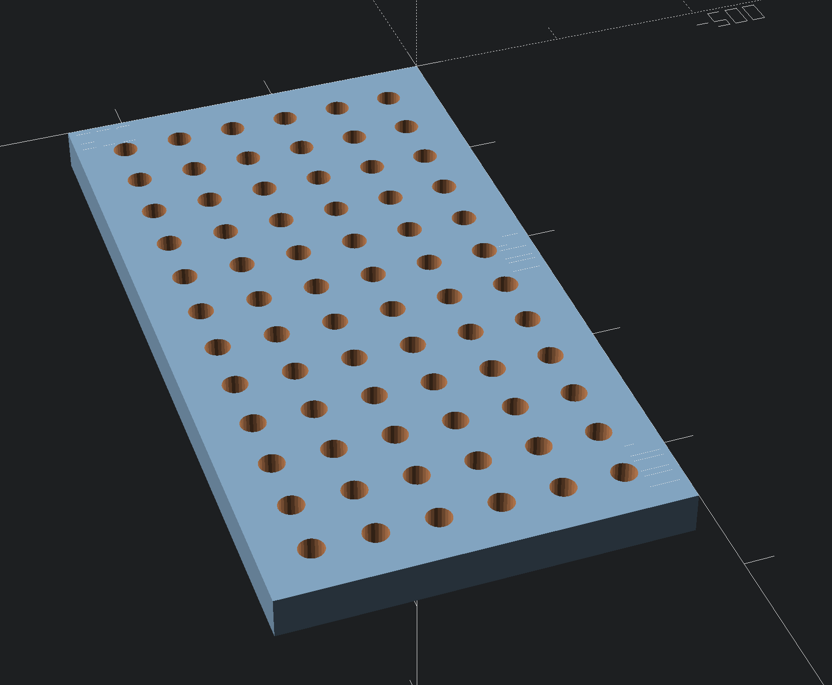
The task of creating an array of holes was recently asked after:
The rather prosaic solution of drawing a column of circles, duping it, rotating the duplicate as needed, and then duping the column and aligning each duplicate as desired was met w/ the observation that it was more steps than were expected:
Here is a way to do this programmatically using freely available tools.
Whilst this tutorial is being built for BlocksCAD, I put together a couple of scripts to do it using the BlocksCAD prerequisite OpenSCAD, which is quite wonderful in and of itself.
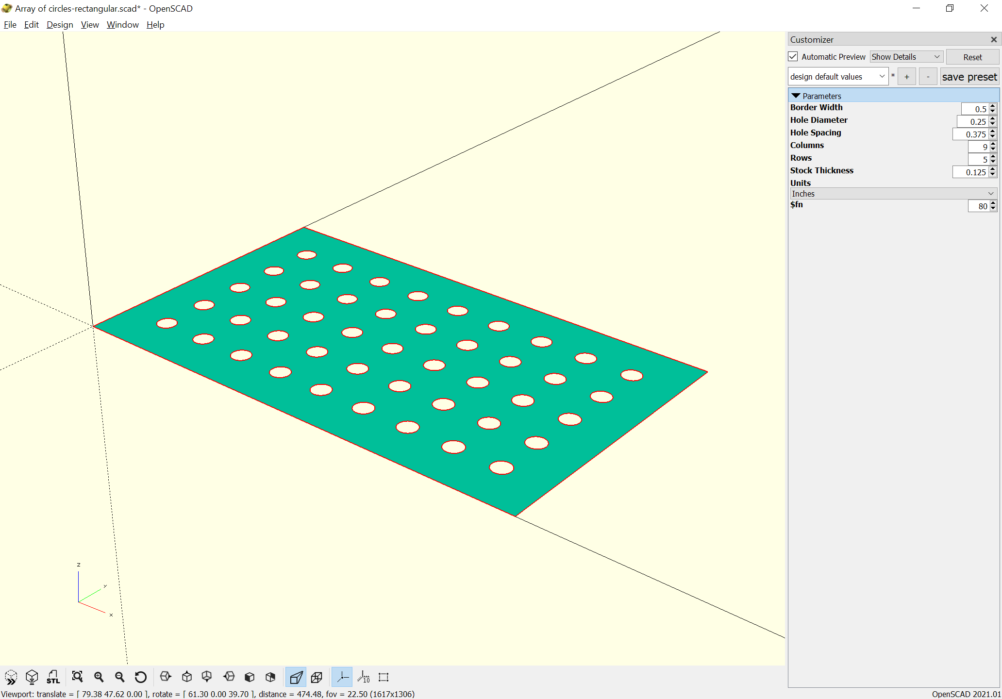
To draw circles and save them as SVG’s:
// Draw a grid of circles
//
// - All values are in mm
// - Adjust the variables, then hit F6 and export as an SVG
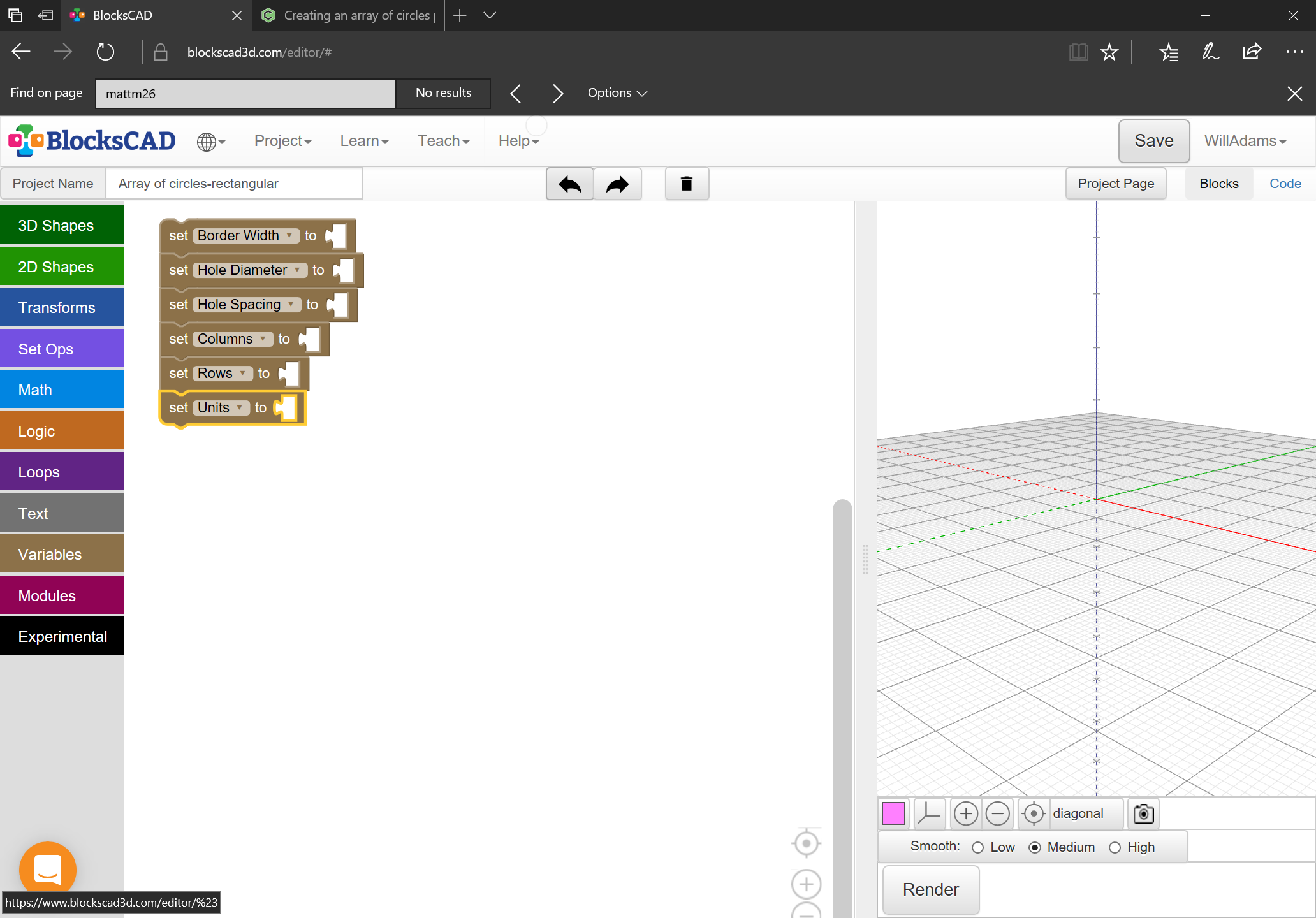
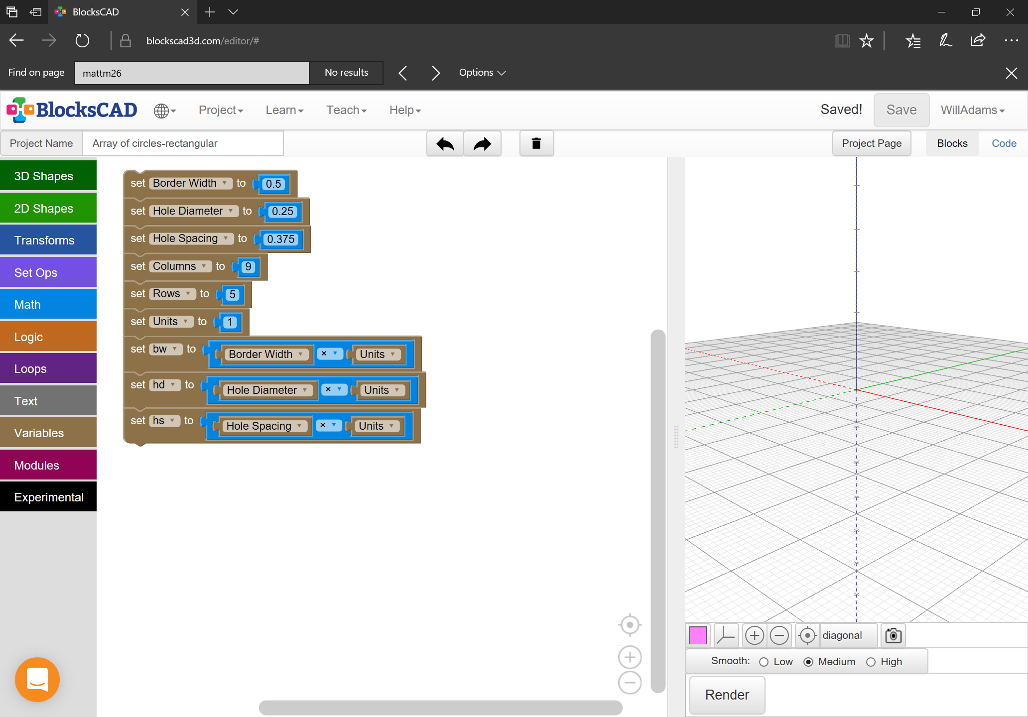
// variables
borderWidth = 30;
holeDiameter = 15;
holeSpacing = 20;
columns = 12;
rows = 6;
// other stuff :)
for (row=[0:rows-1],column = [0:columns-1]) {
hole(row,column);
}
module hole(row, column) {
x = column * (holeDiameter + holeSpacing);
y = row * (holeDiameter + holeSpacing);
translate([x + borderWidth,y + borderWidth,0]) {
circle(d=holeDiameter);
}
}
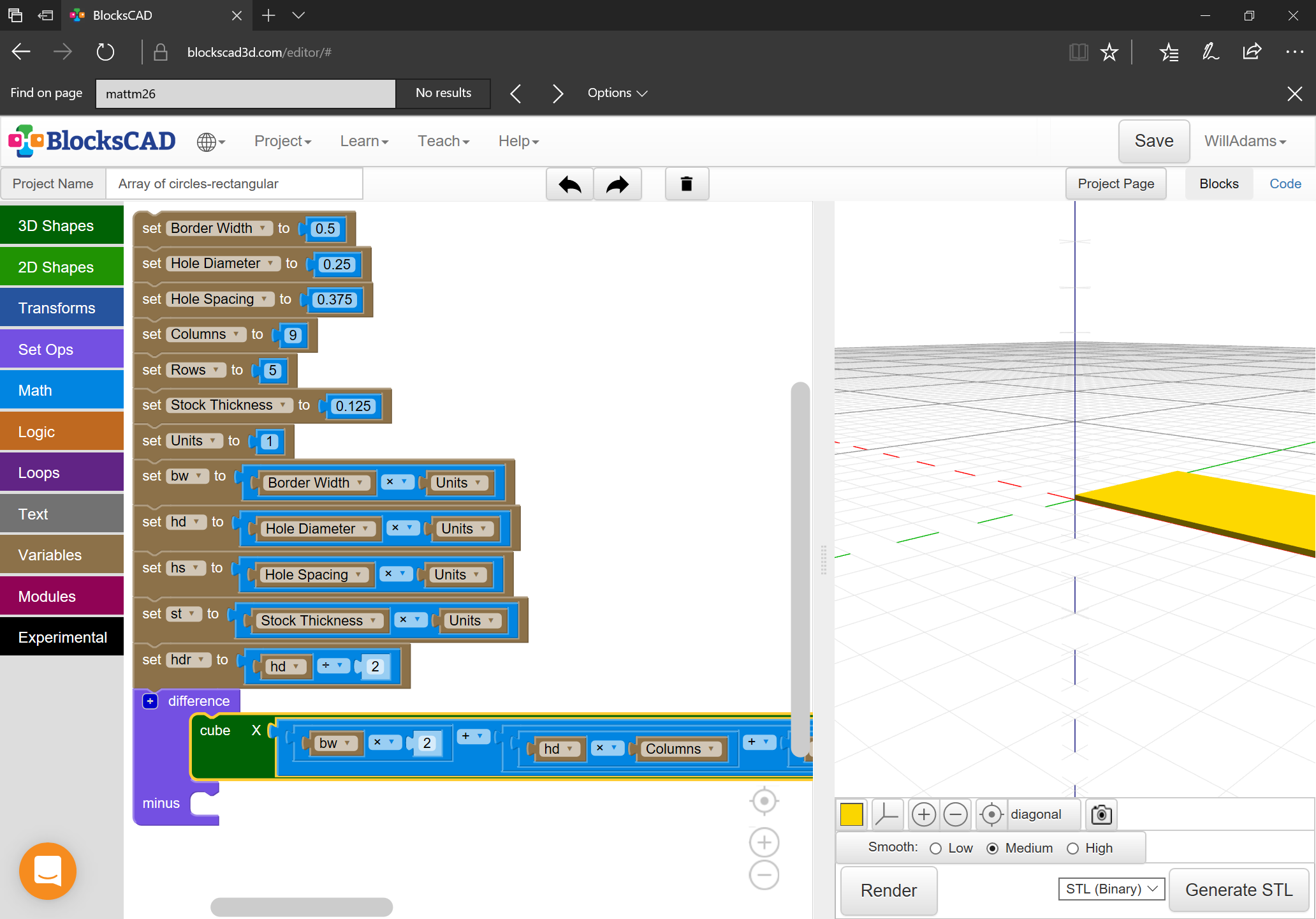
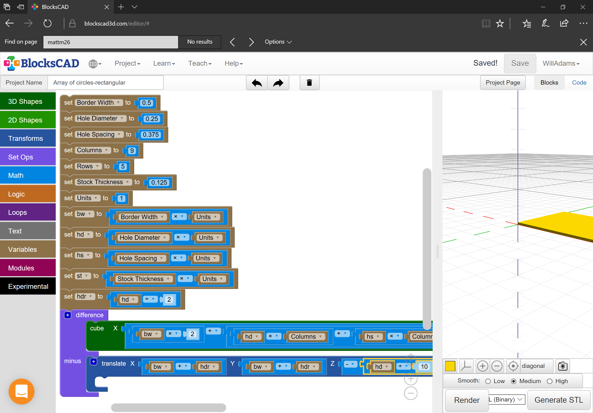
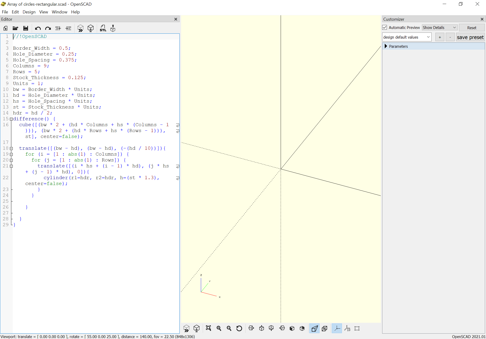
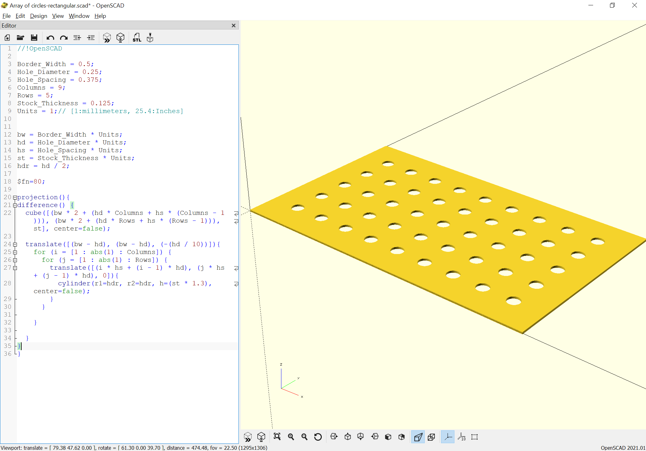
To draw holes in a block and save it as an STL or similar:
// Draw a grid of circles in a bit of stock
//
// - All values are in mm
// - Adjust the variables, then hit F6 and export as an STL or similar
// variables
stockThickness = 25;
borderWidth = 30;
holeDiameter = 15;
holeSpacing = 20;
columns = 12;
rows = 6;
// other stuff :)
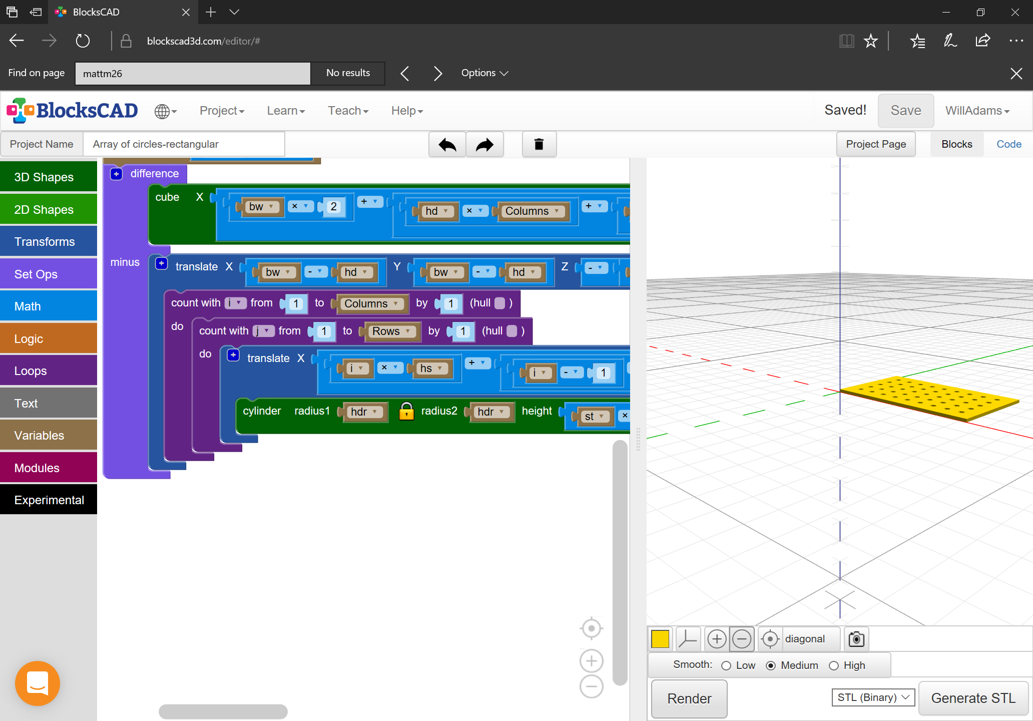
difference(){
stock();
for (row=[0:rows-1],column = [0:columns-1]) {
hole(row,column);
}
}
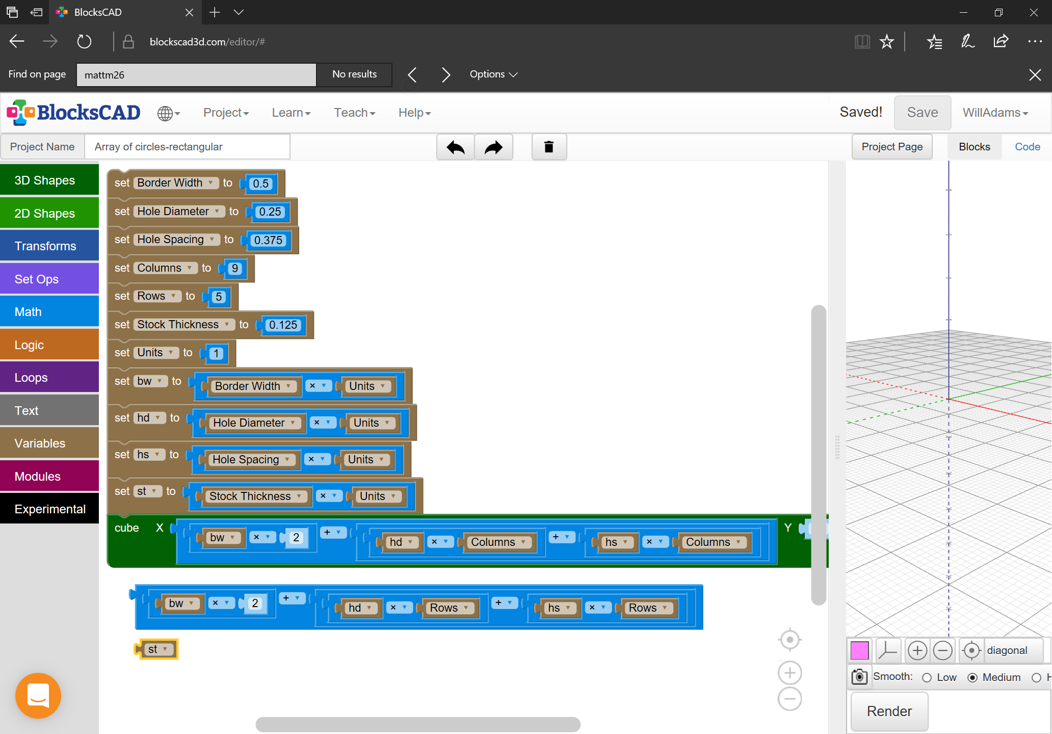
module stock() {
cube([
(borderWidth*2) + ((columns-1)*(holeSpacing+holeDiameter)),
(borderWidth*2) + ((rows-1)*(holeSpacing+holeDiameter)),
,stockThickness
]);
}
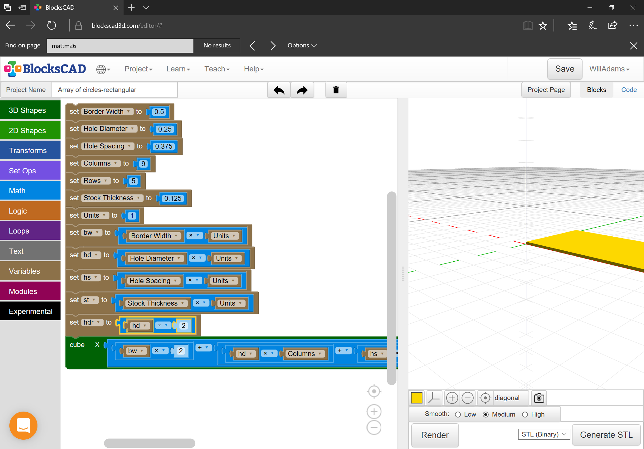
module hole(row, column) {
x = column * (holeDiameter + holeSpacing);
y = row * (holeDiameter + holeSpacing);
translate([x + borderWidth,y + borderWidth,-1]) {
cylinder(stockThickness+2,d=holeDiameter,center=false);
}
}
There is a feature in CC under transform called Allign Vectors. Position the first row of holes where you want them. Then select all in each row and use Allign Vectors to line them up with the first row. Play with it and you will see what it does
@Gerry — no fair skipping forward — we’ll get to OpenSCAD, but won’t use an STL to get out of it, since that’s rather limiting in terms of CAM tool choices.
@baricl — unfortunately, CC’s current alignment options only allow aligning at extrema, and doesn’t have an option for doing two axes at once, so one would have to align twice for each instance — dragging into alignment is instead a single operation and fewer clicks.