Conversion / tracing doesn’t yield as clean / accurate / precise a result.
Some duplication and insetting yielded:

2 Likes
That looks much better with the updated subdivisions.
1 Like
As requested on support…
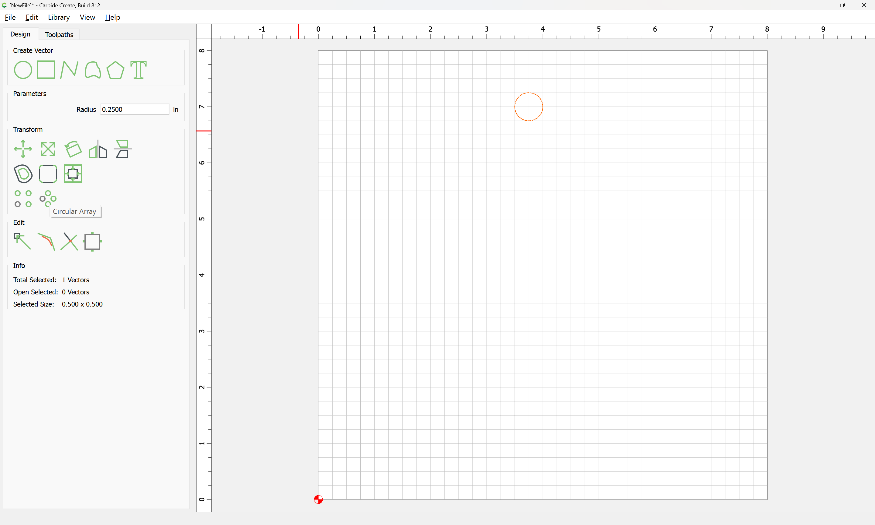
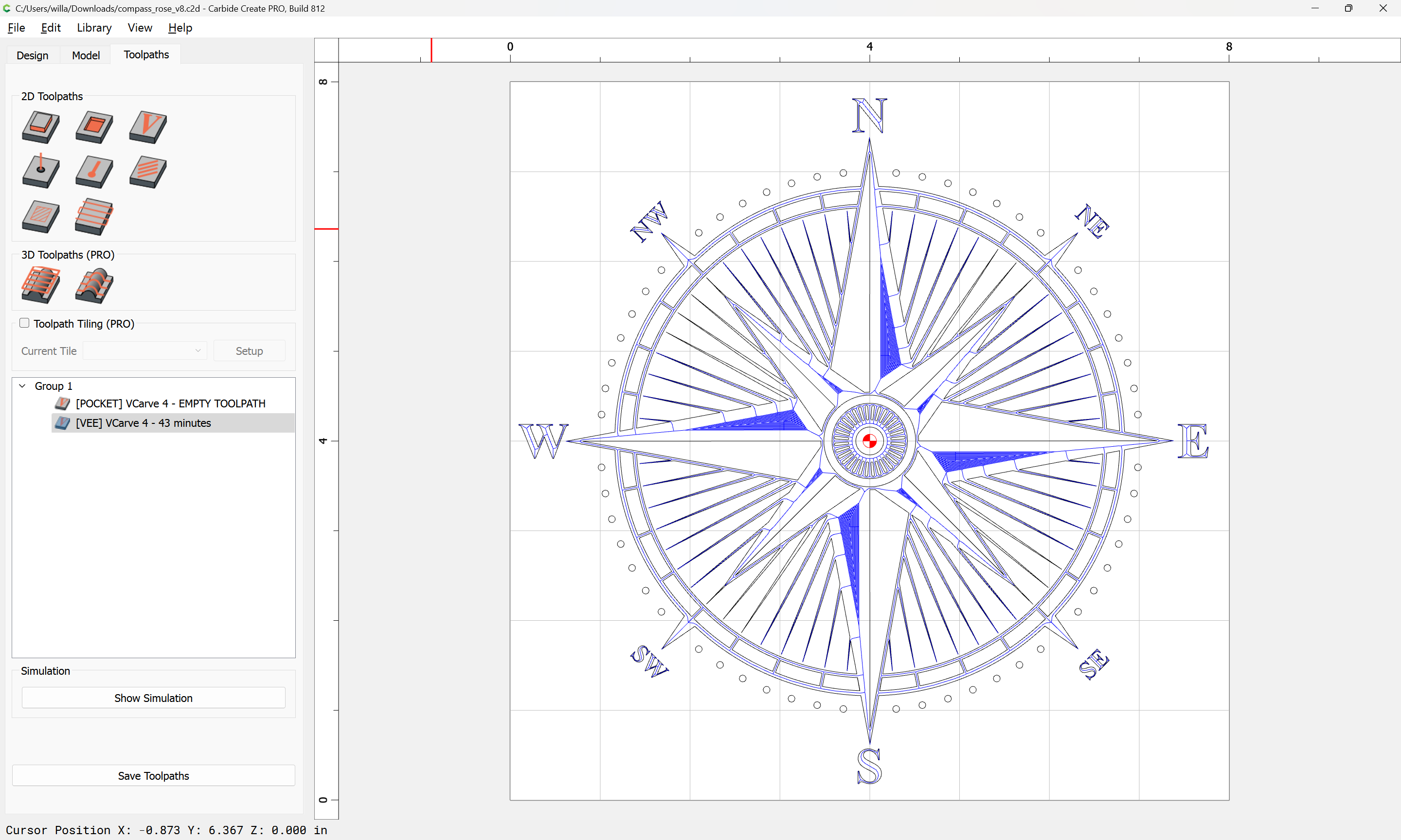
Since the above tutorial was posted, Carbide Create has gained a “Circular Array” tool:
so we will use the (currently new, currently in open beta) v8:
to re-create this.
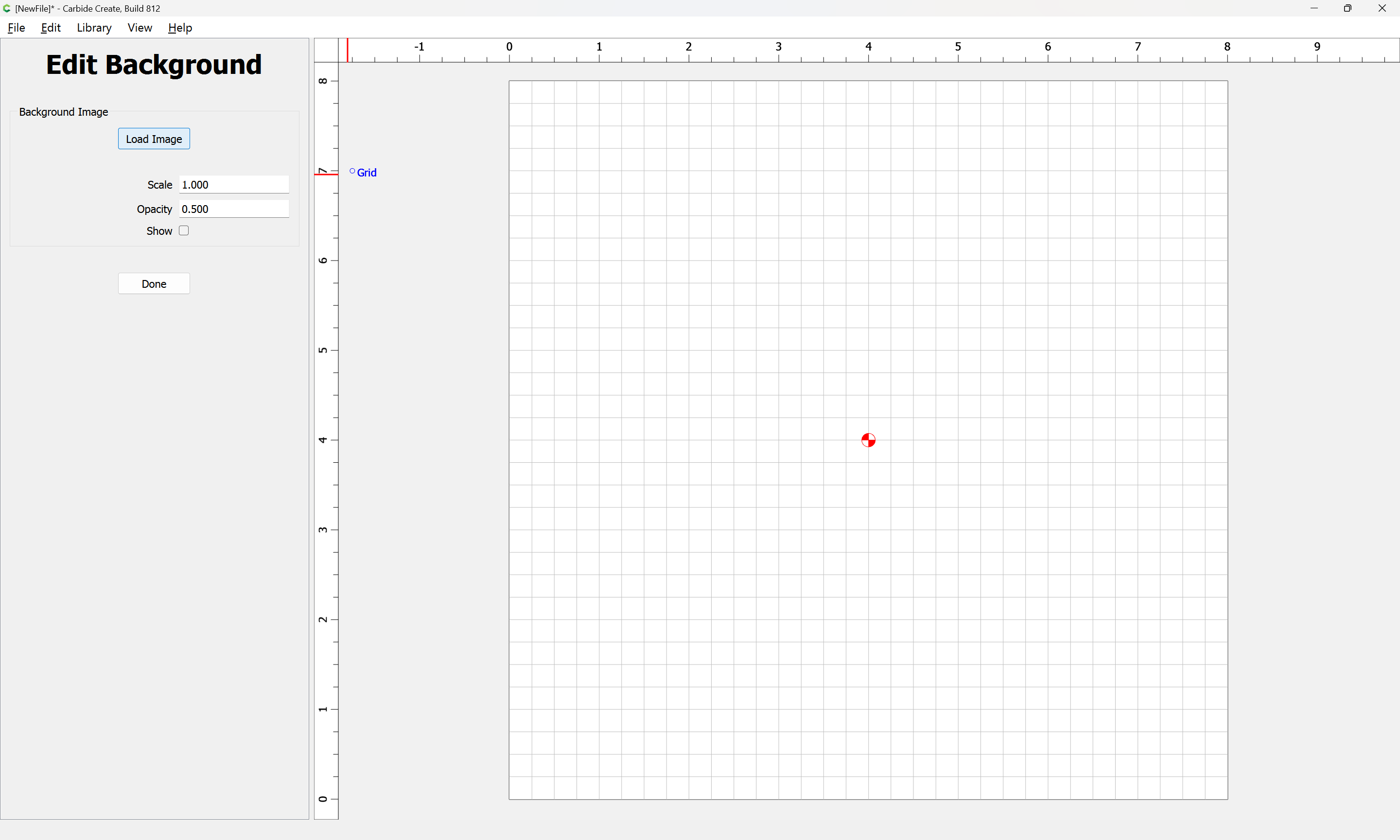
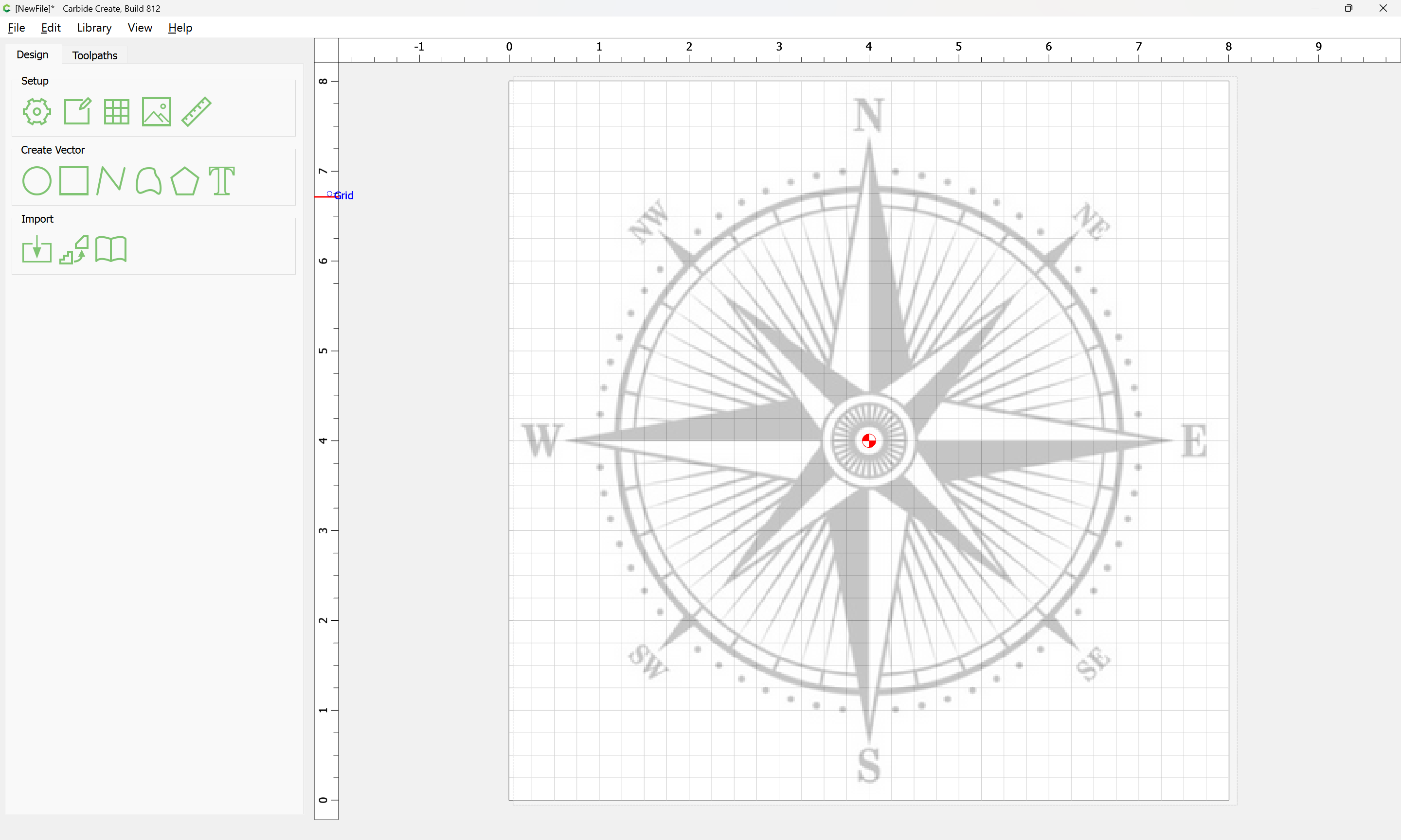
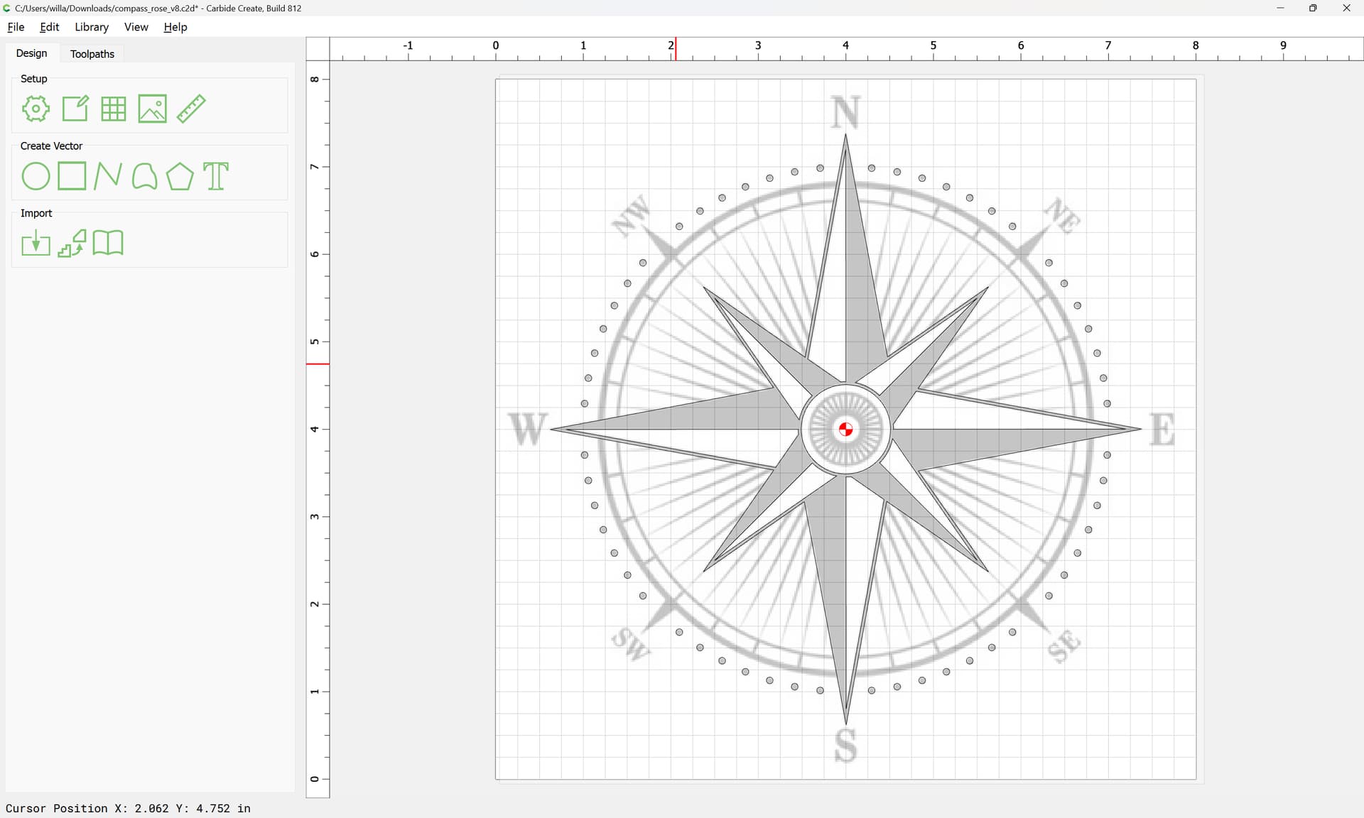
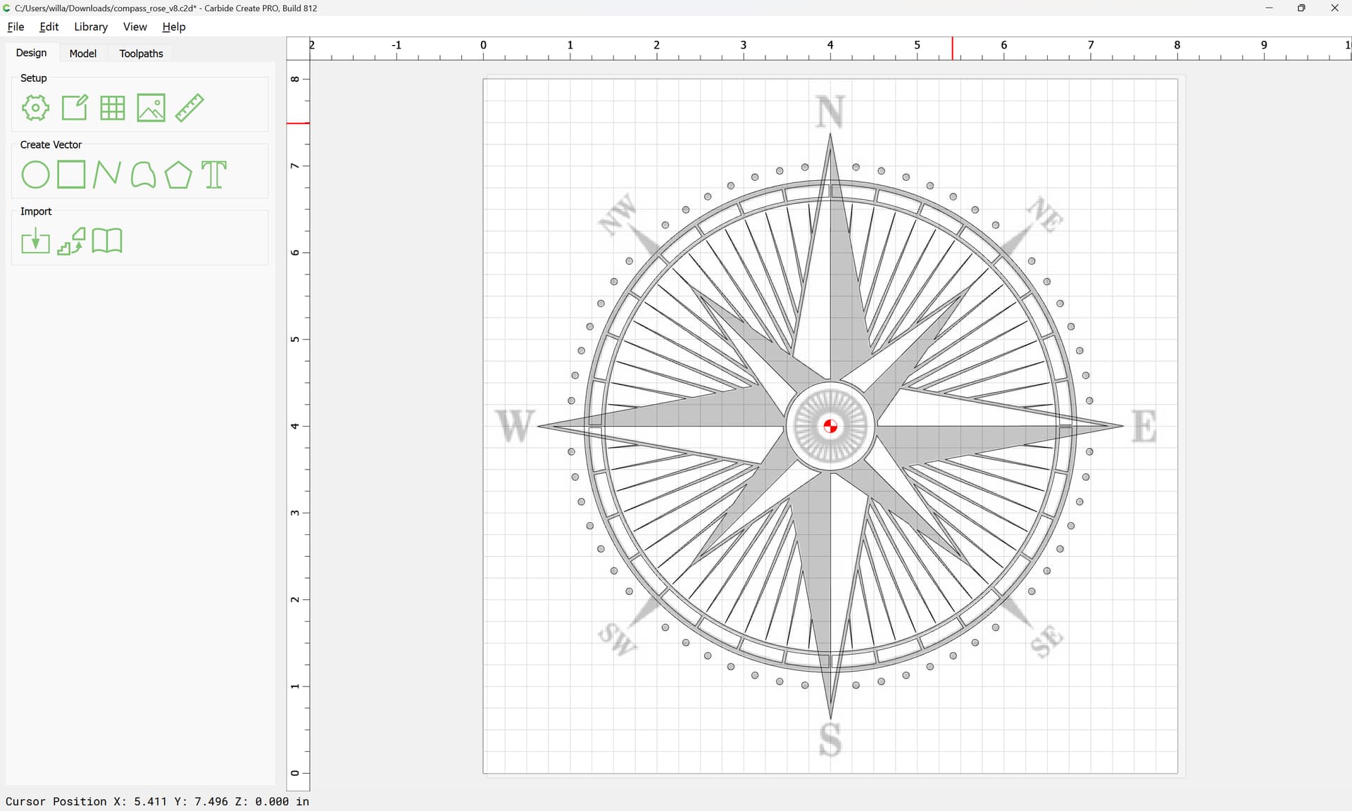
We will work at 8" x 8":
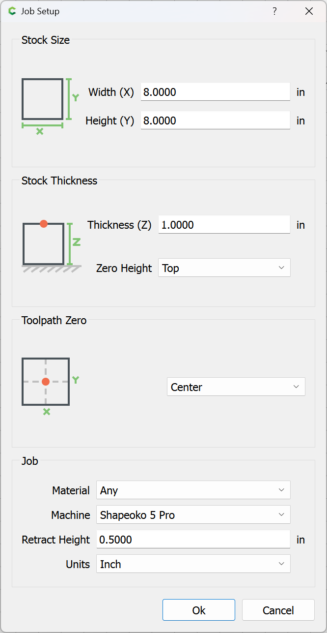
with the origin at the center:
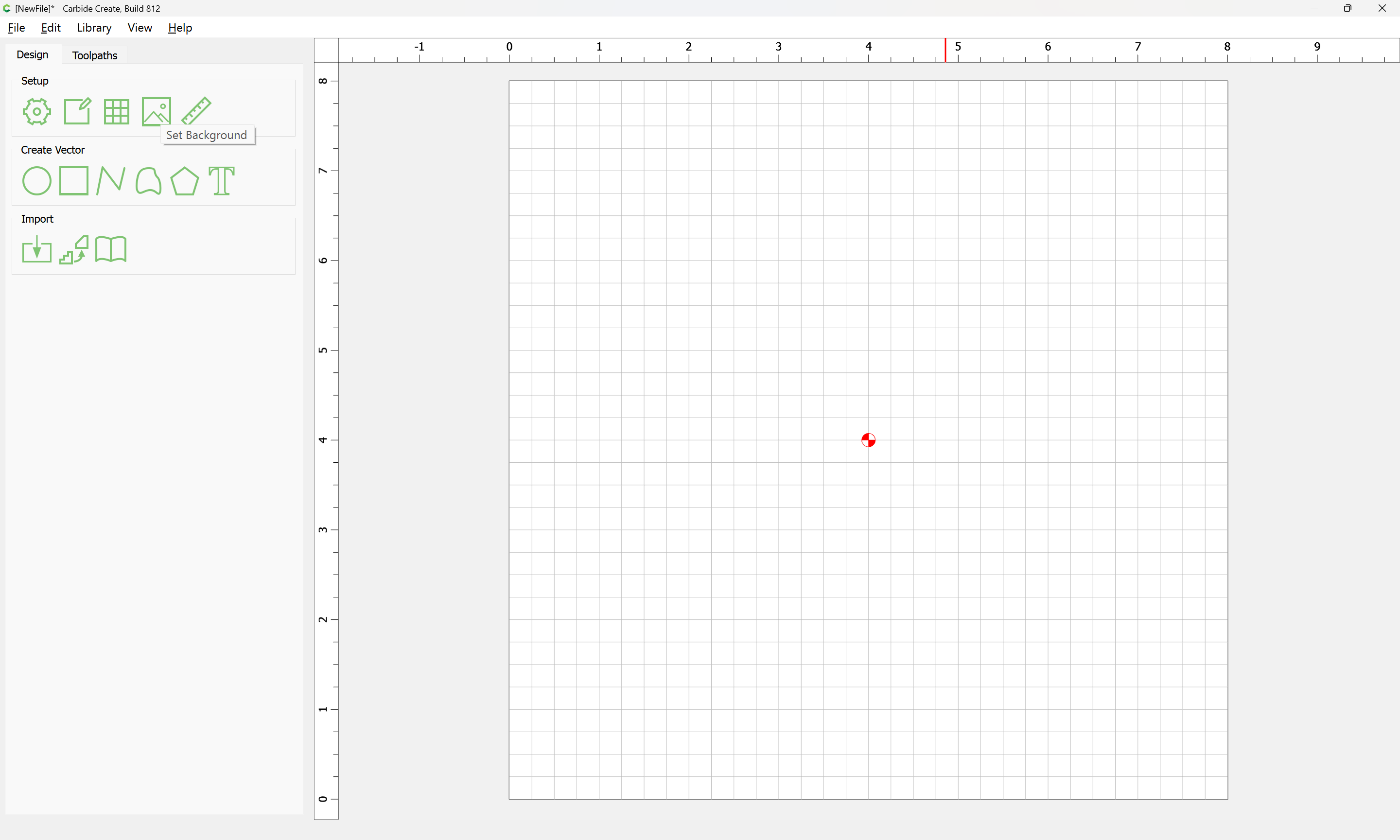
as before we “Set Background”:
“Load Image”
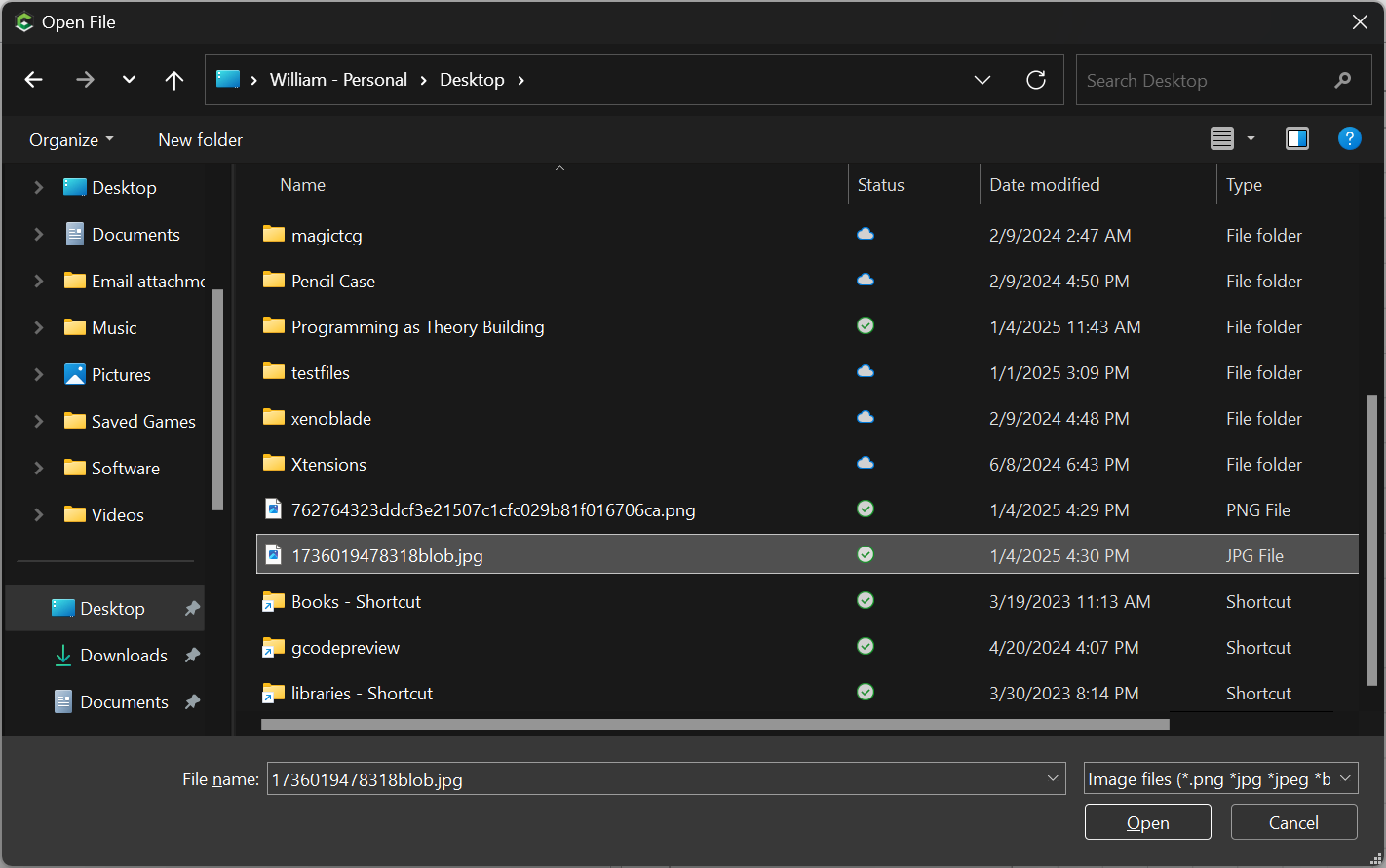
selecting the file:
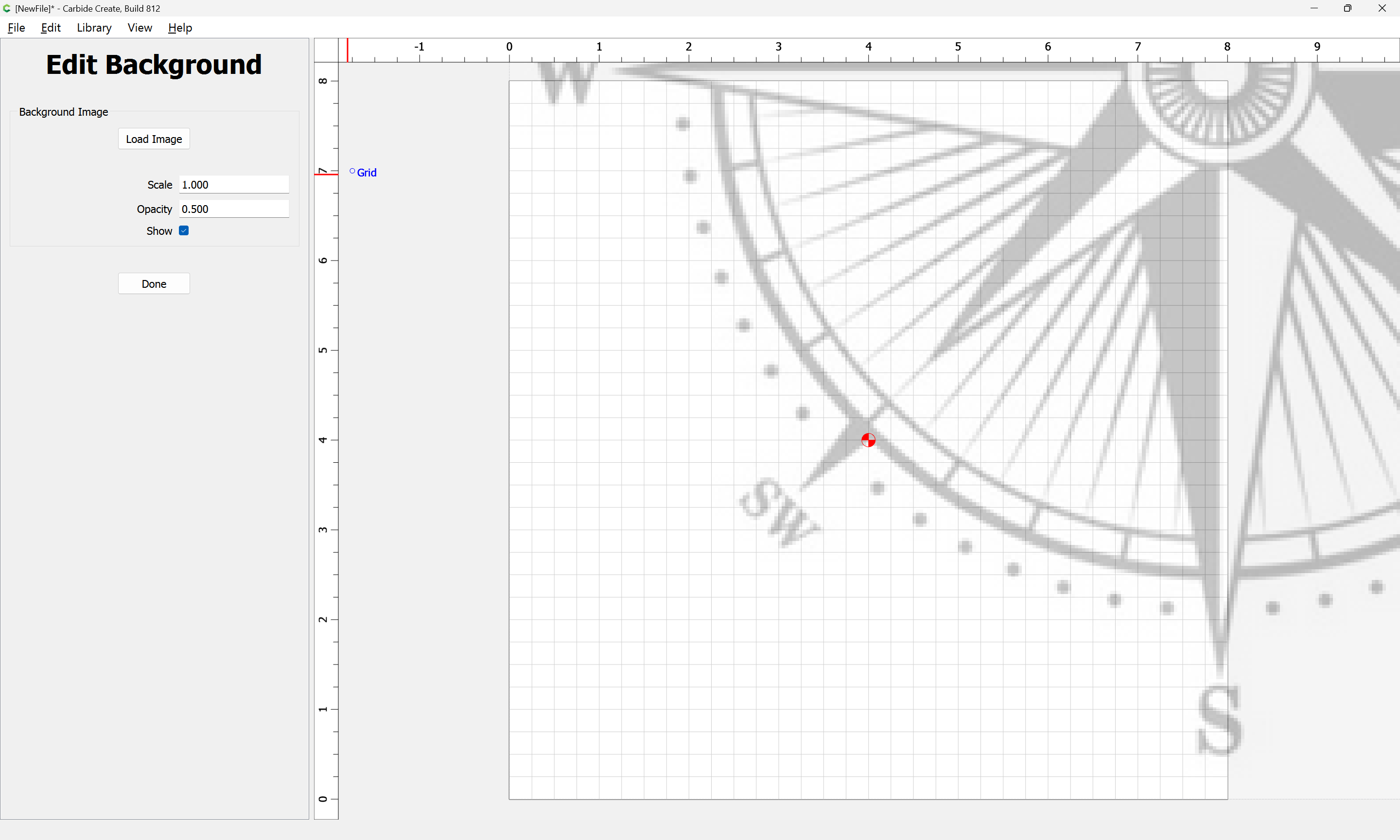
and adjust size and position as necessary, zooming if need be to make sure things align:
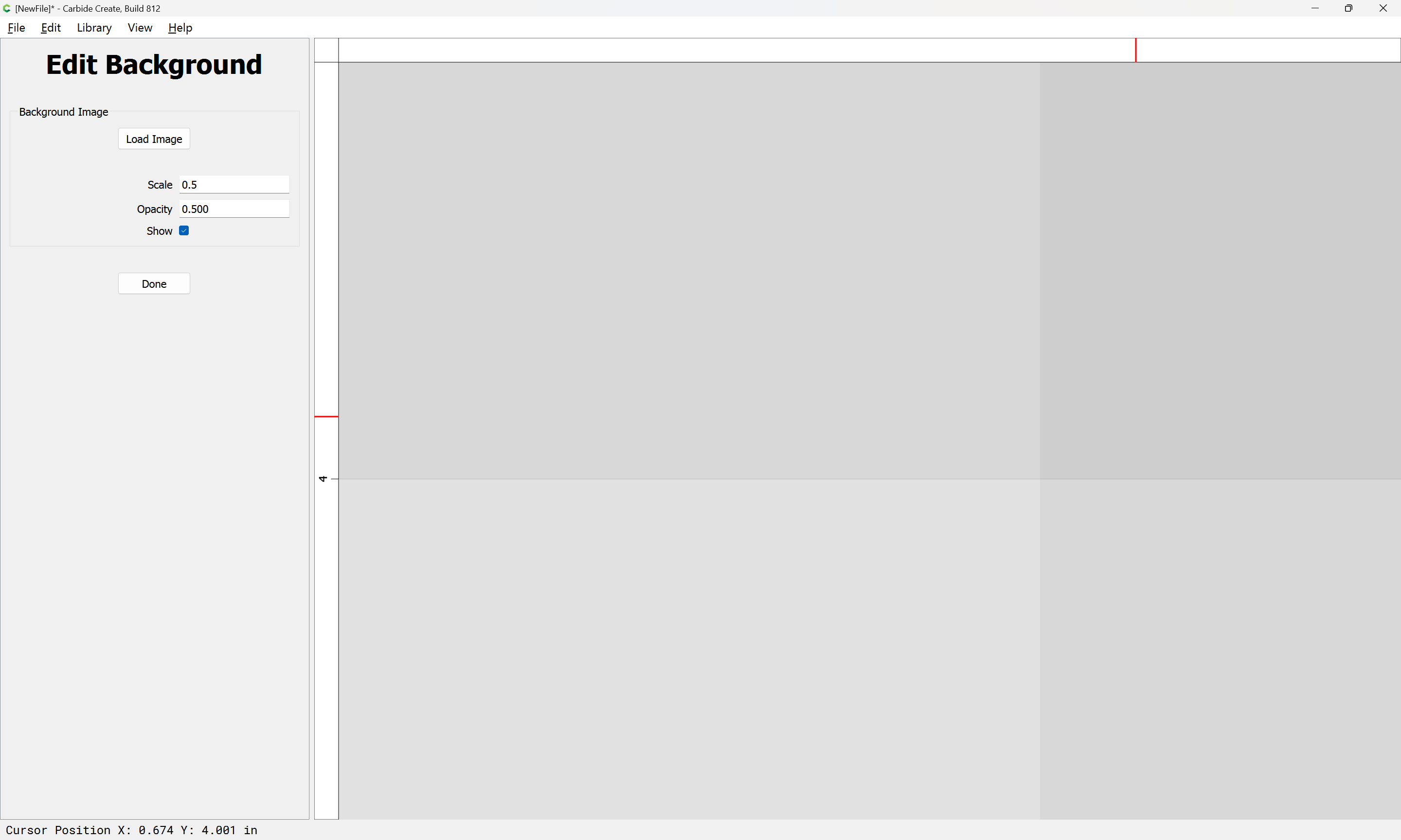
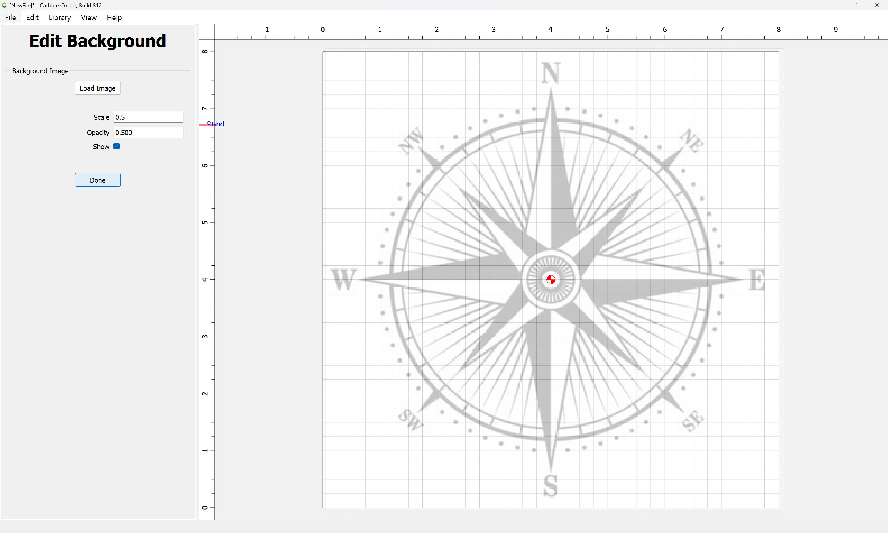
Done
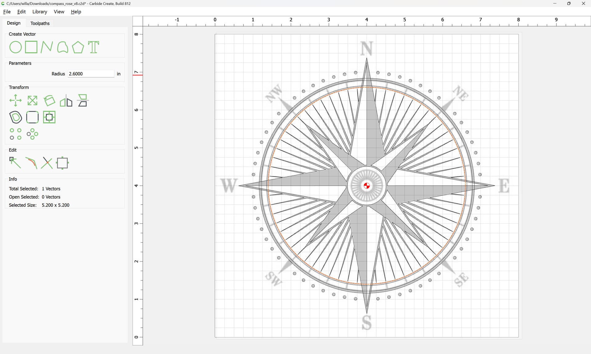
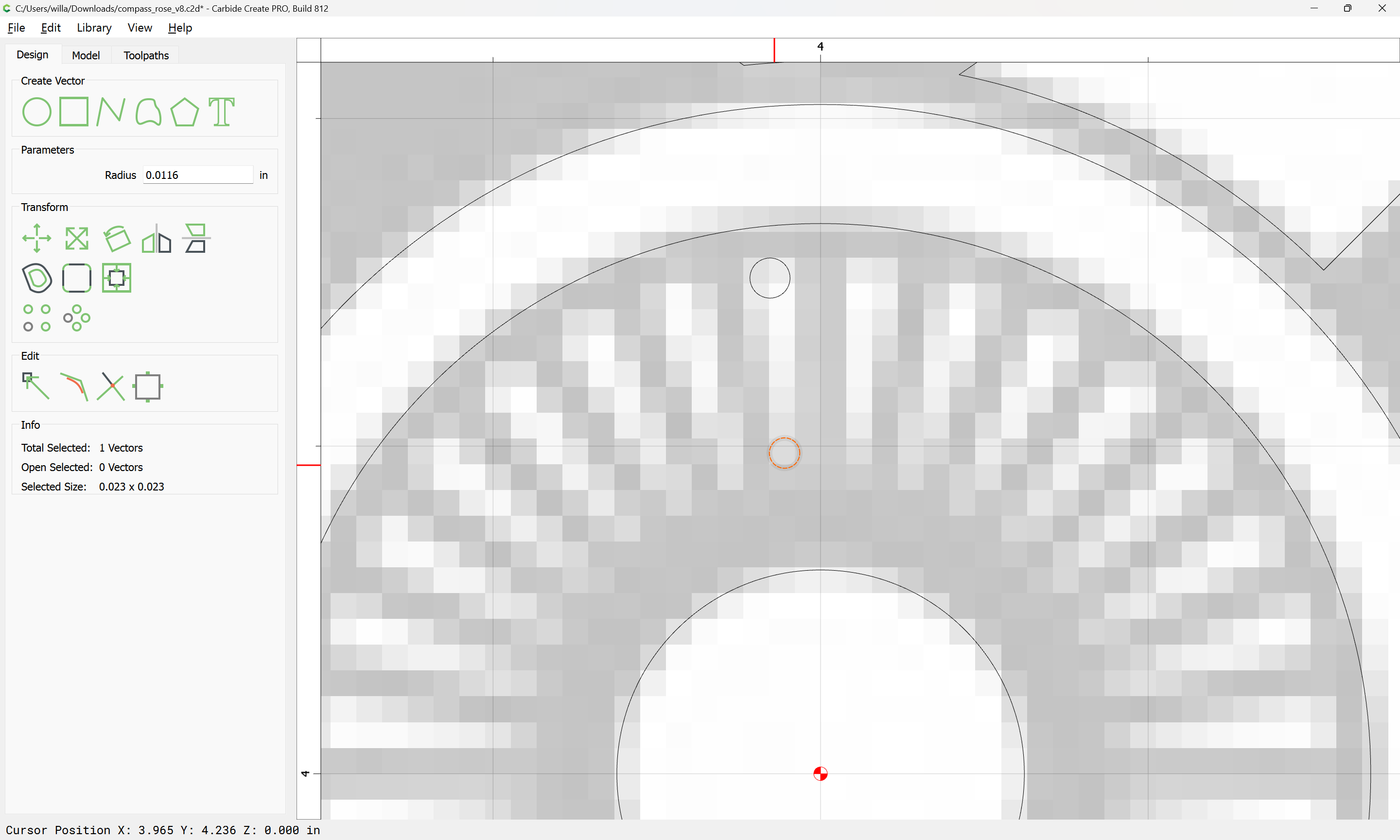
We start with the circles:
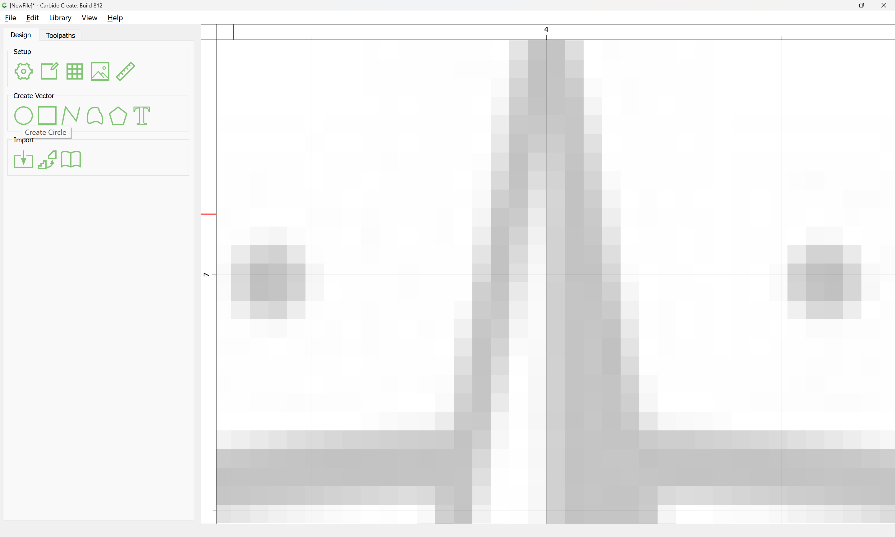
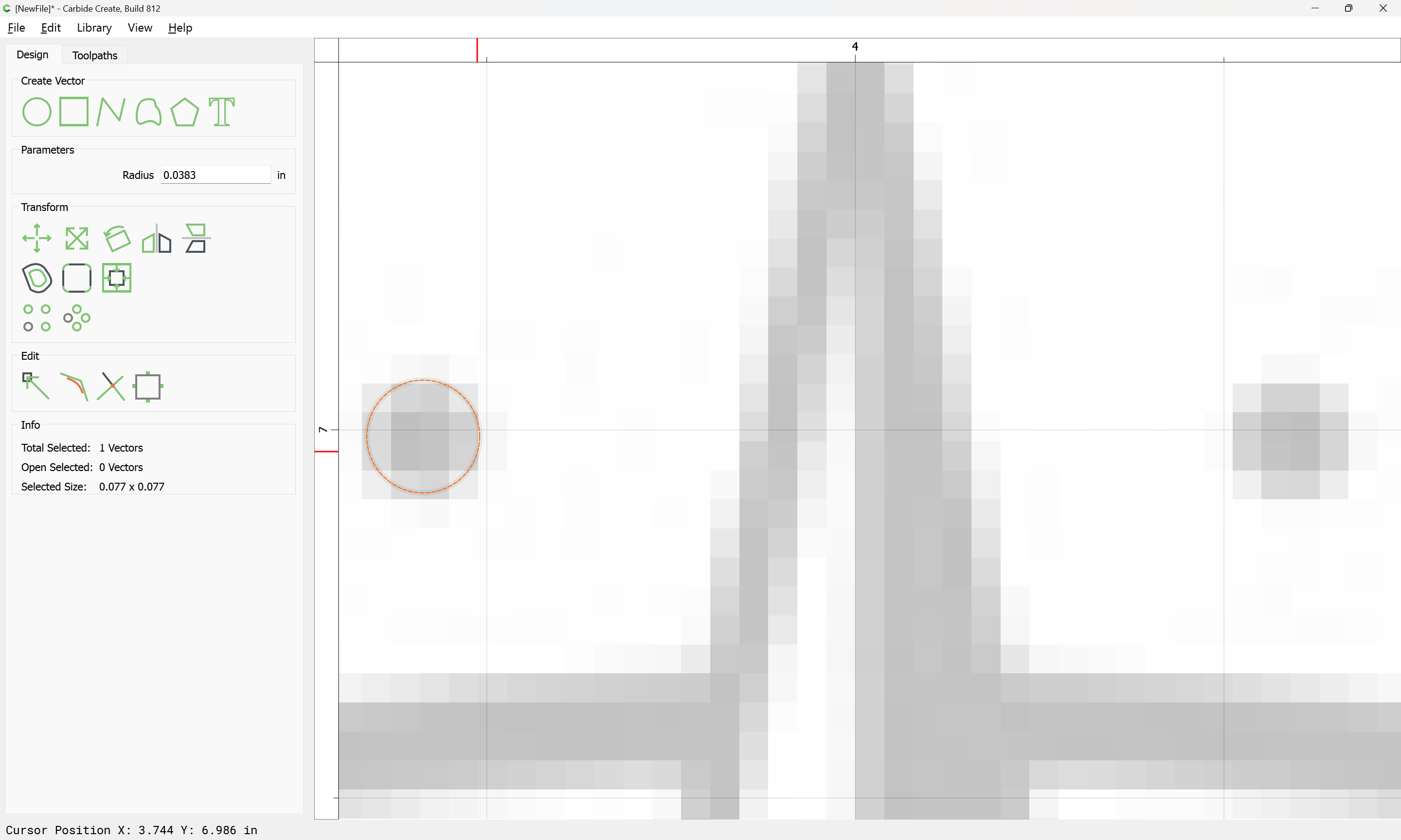
positioning the first on a grid point aligned with the center axis:
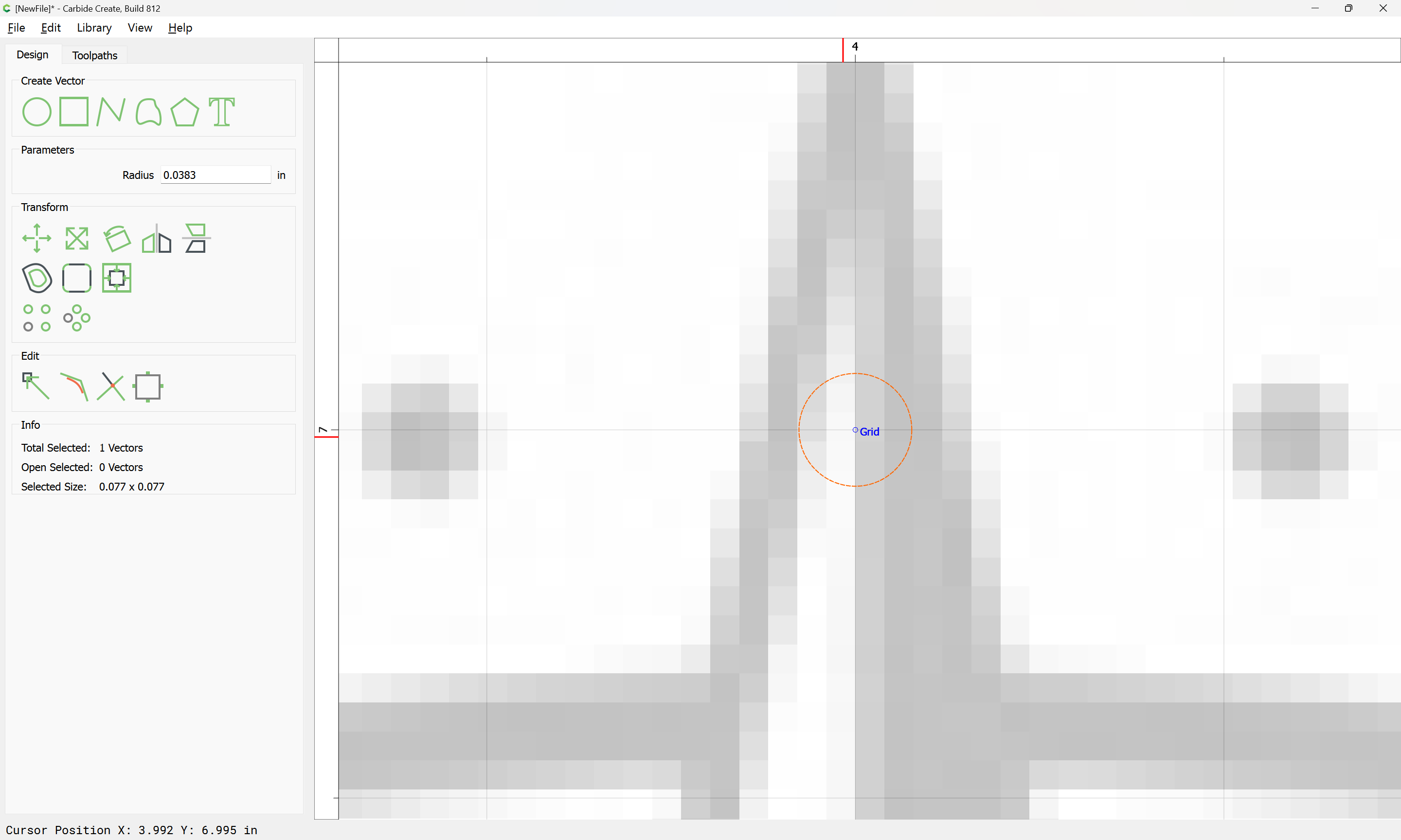
which seems sufficiently higher than the surrounding ones that it should be correct:
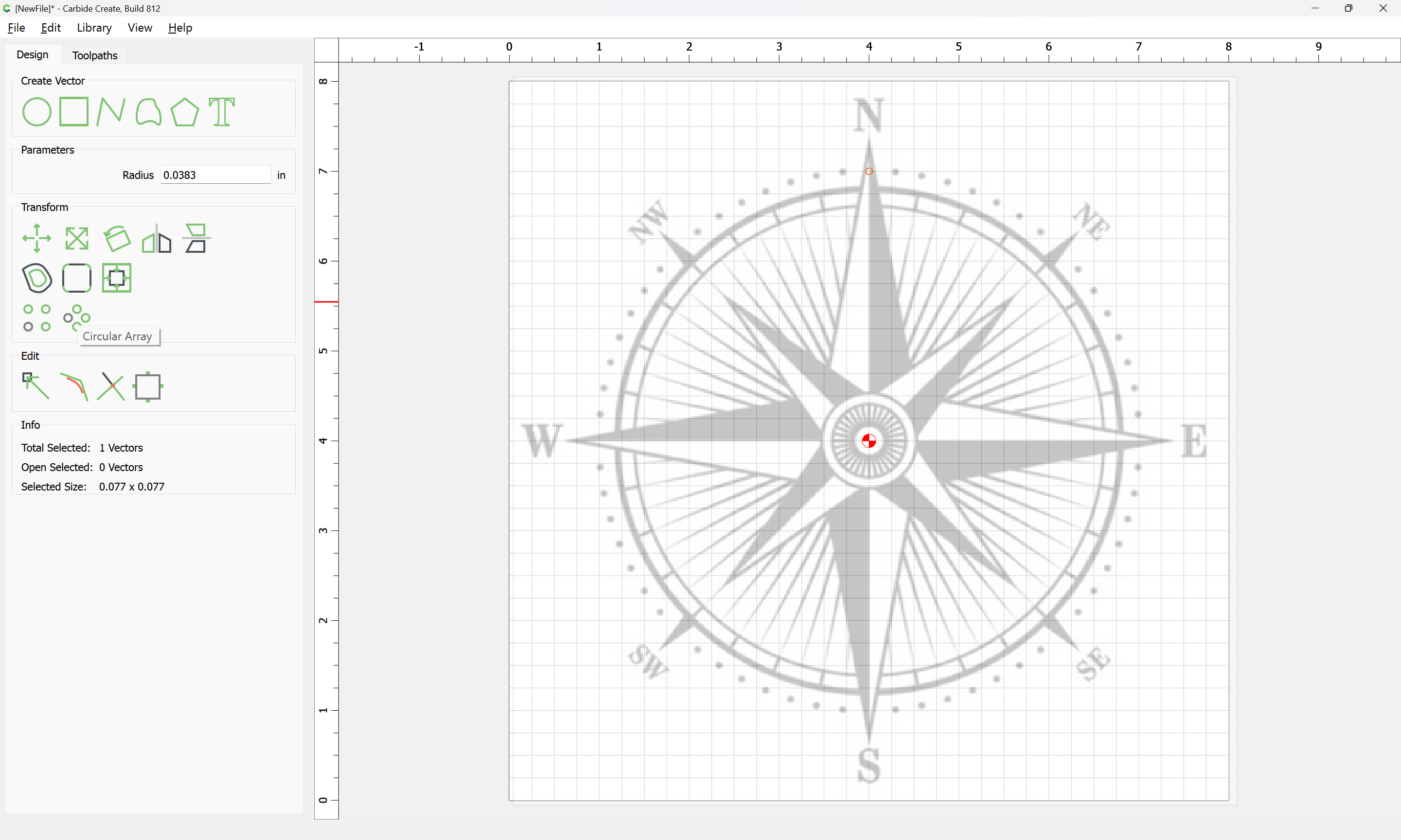
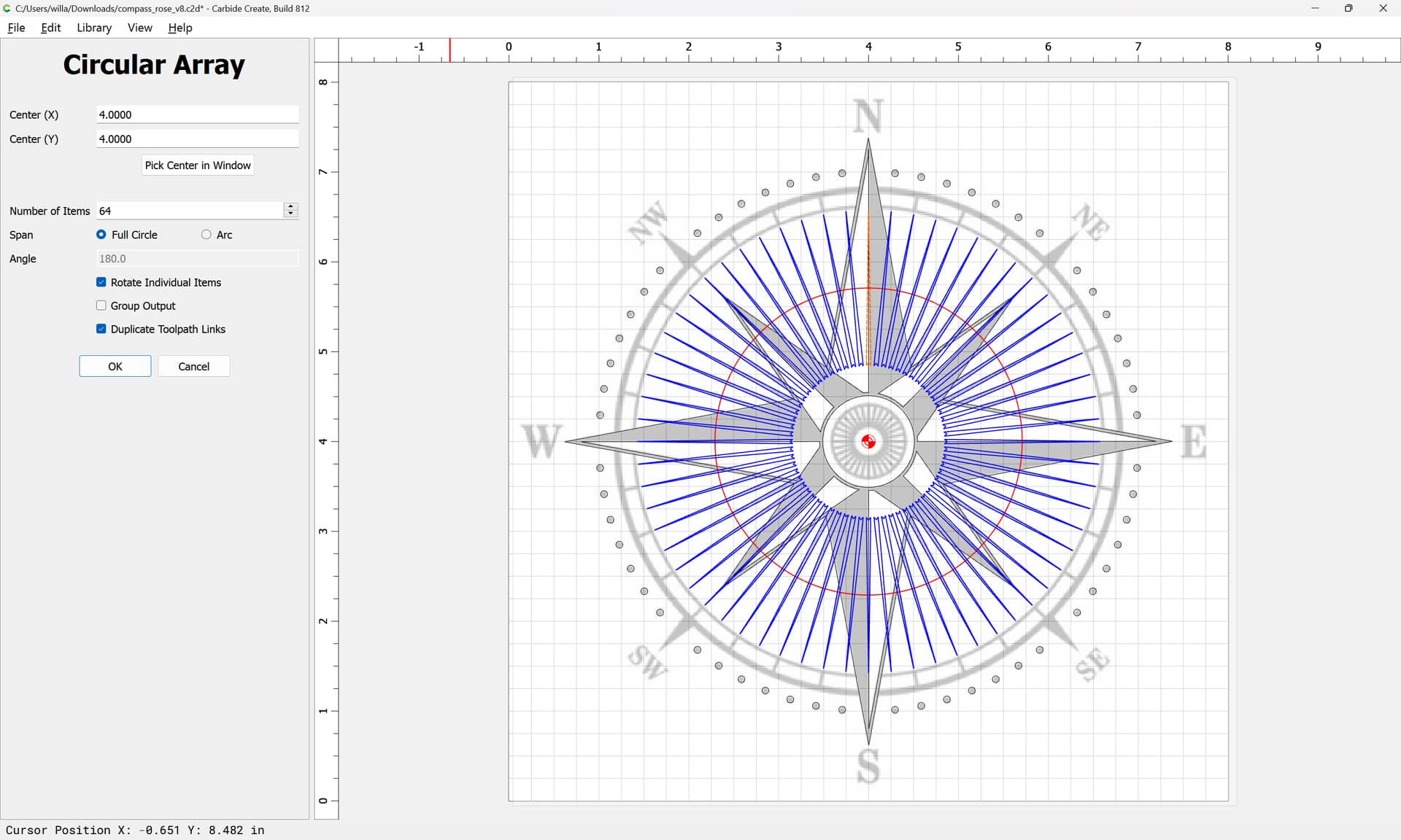
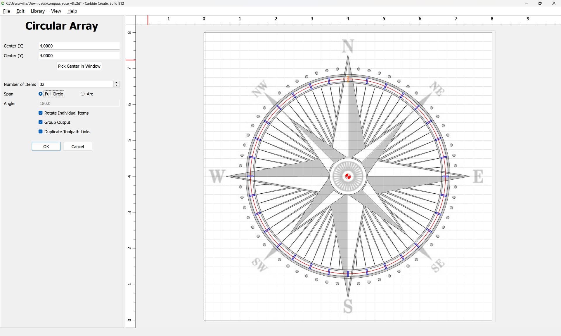
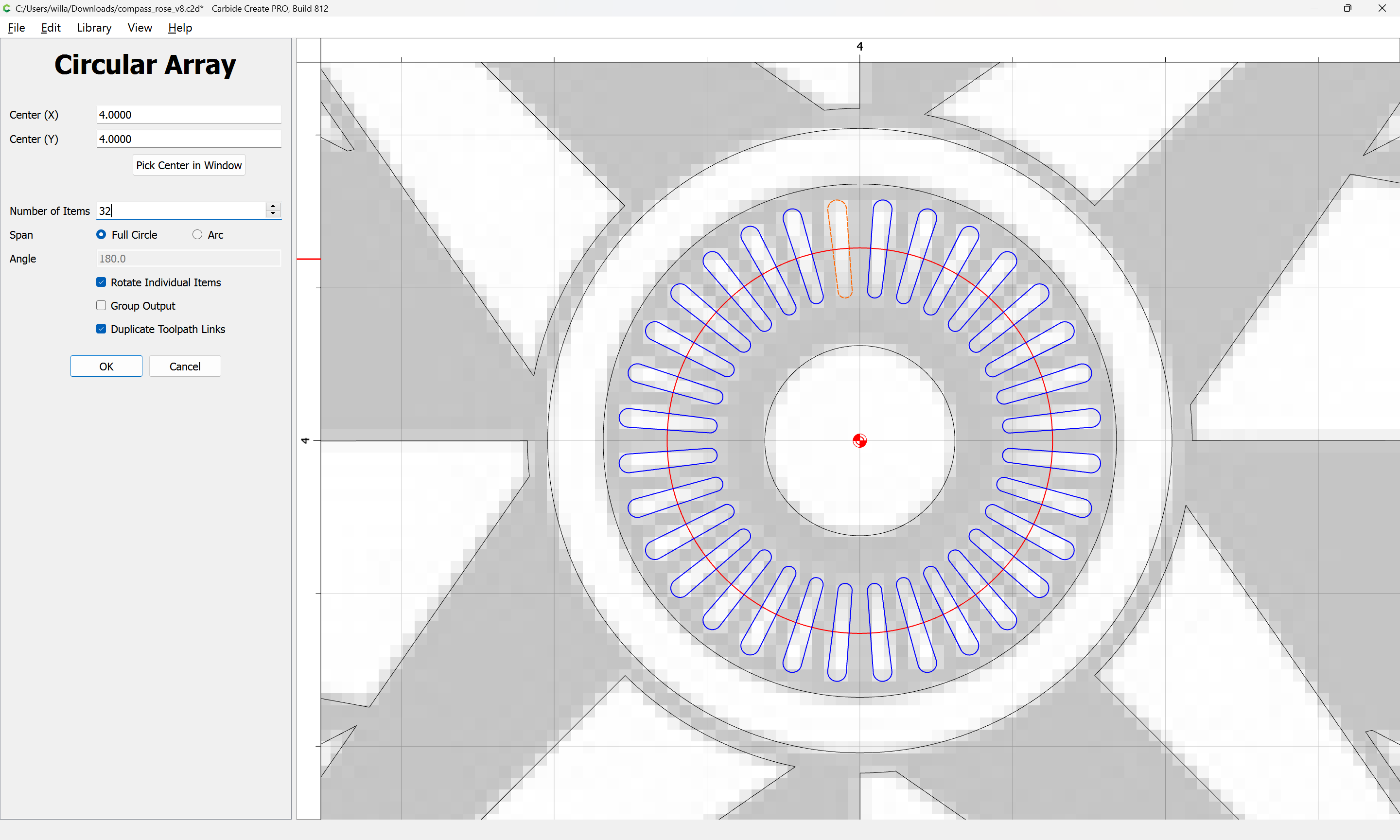
“Circular Array”
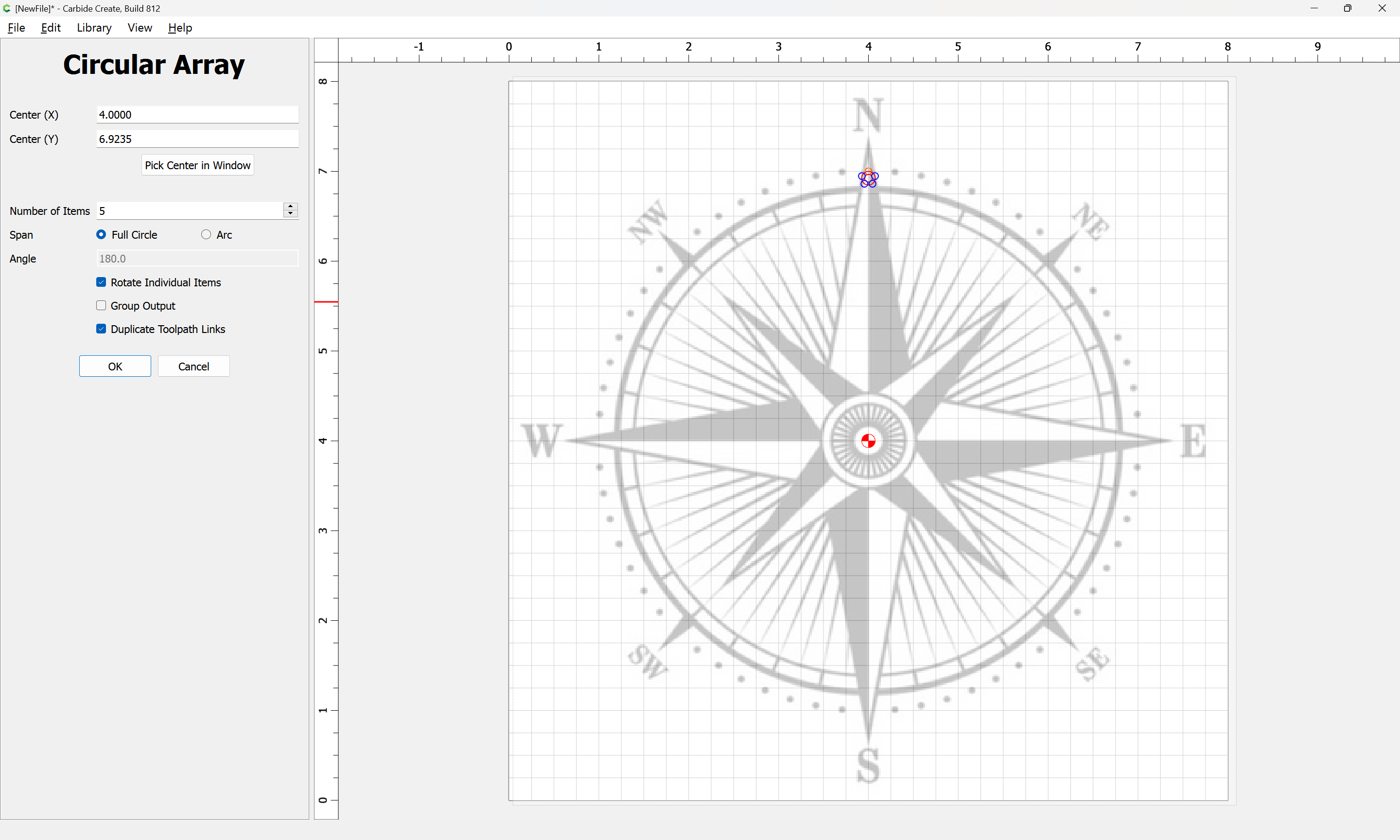
Adjust the parameters as necessary:
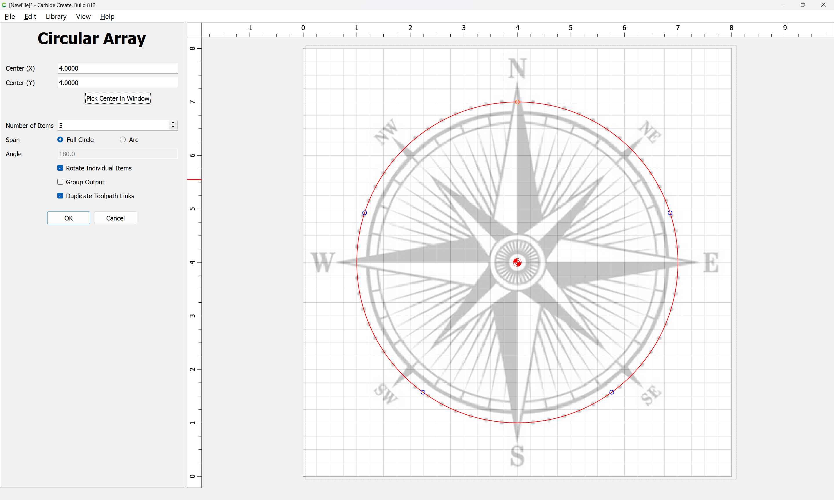
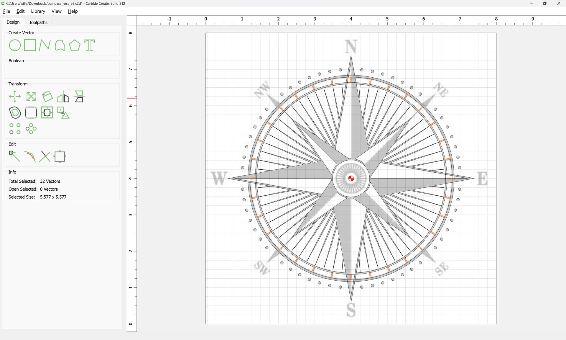
Count the circles to arrive at:
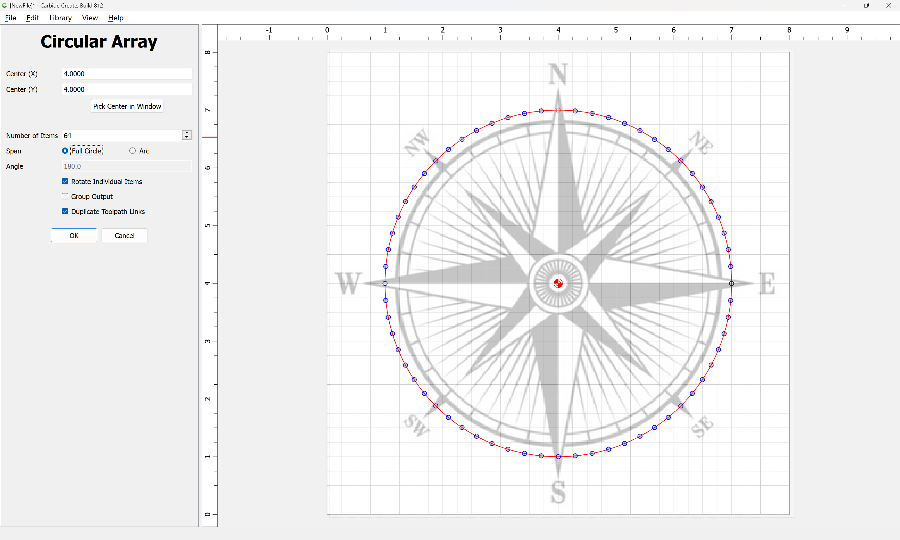
OK
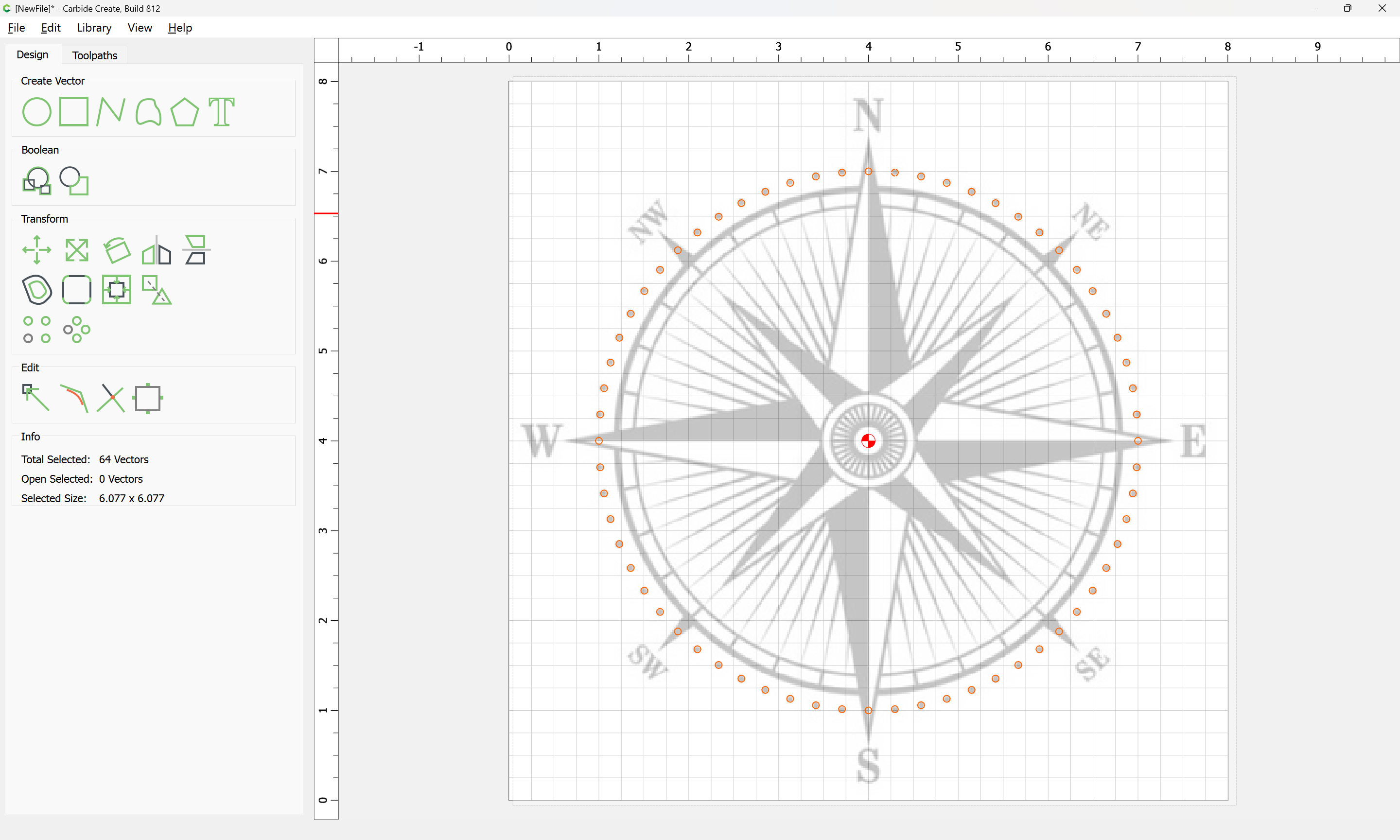
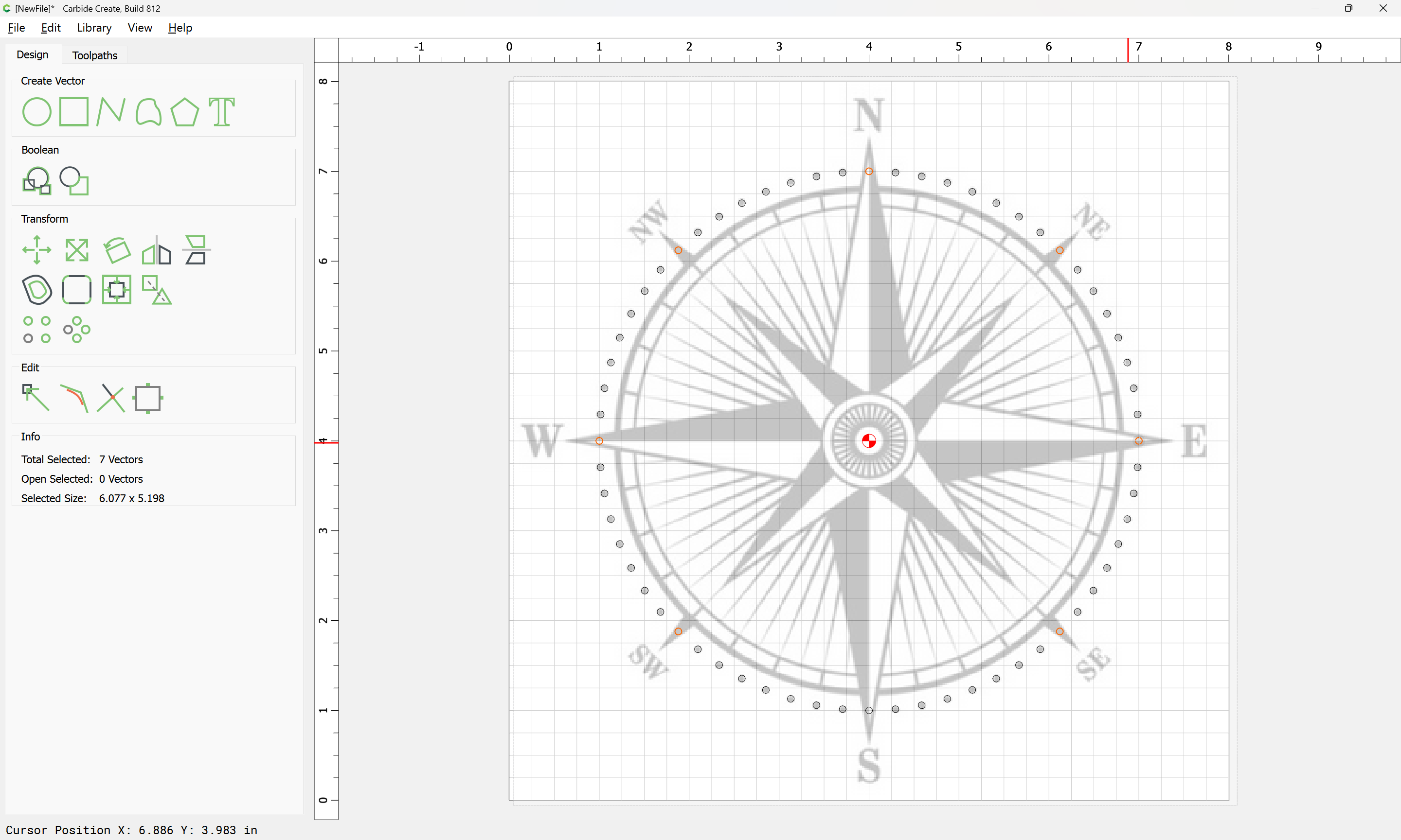
Delete the unnecessary ones:
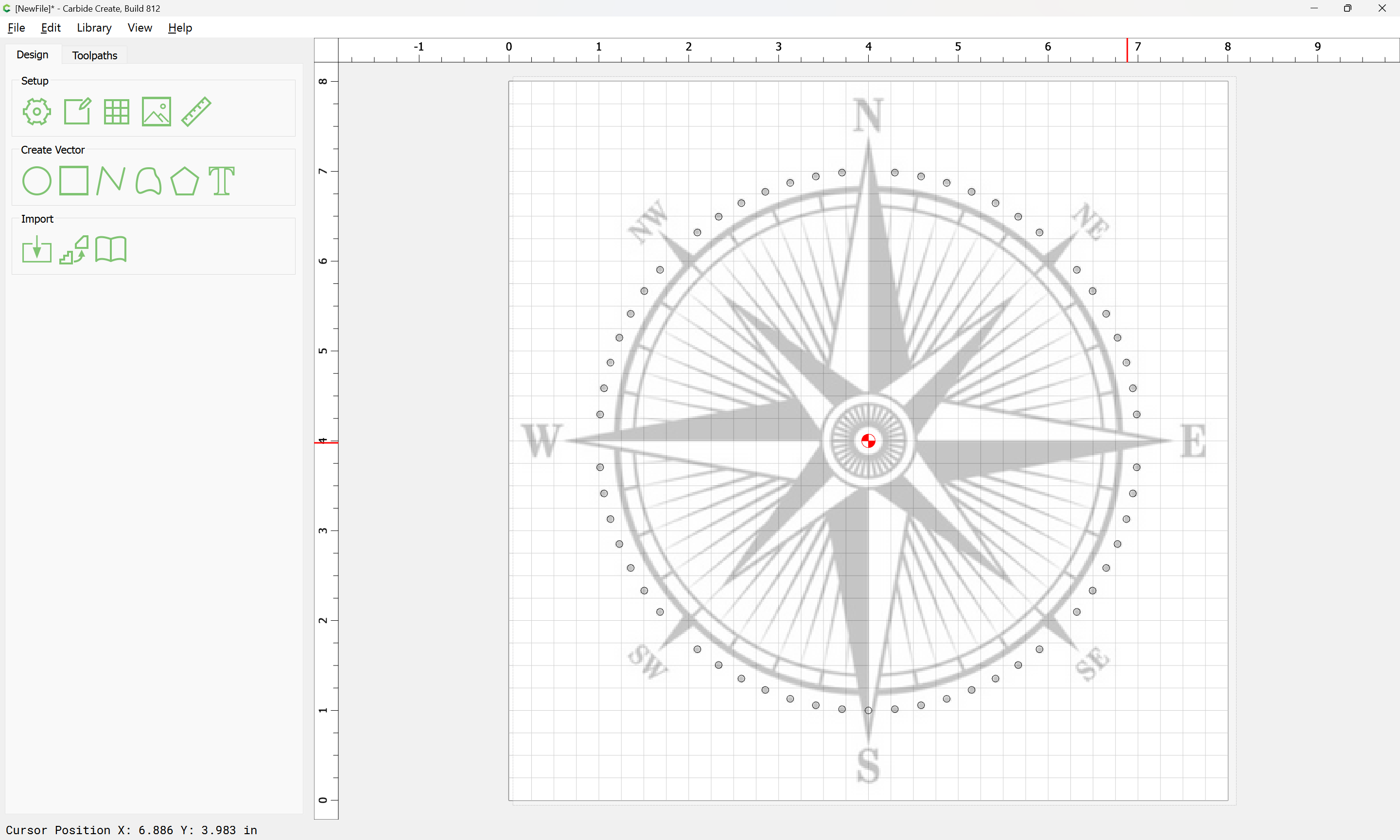
Then draw the next element and repeat…
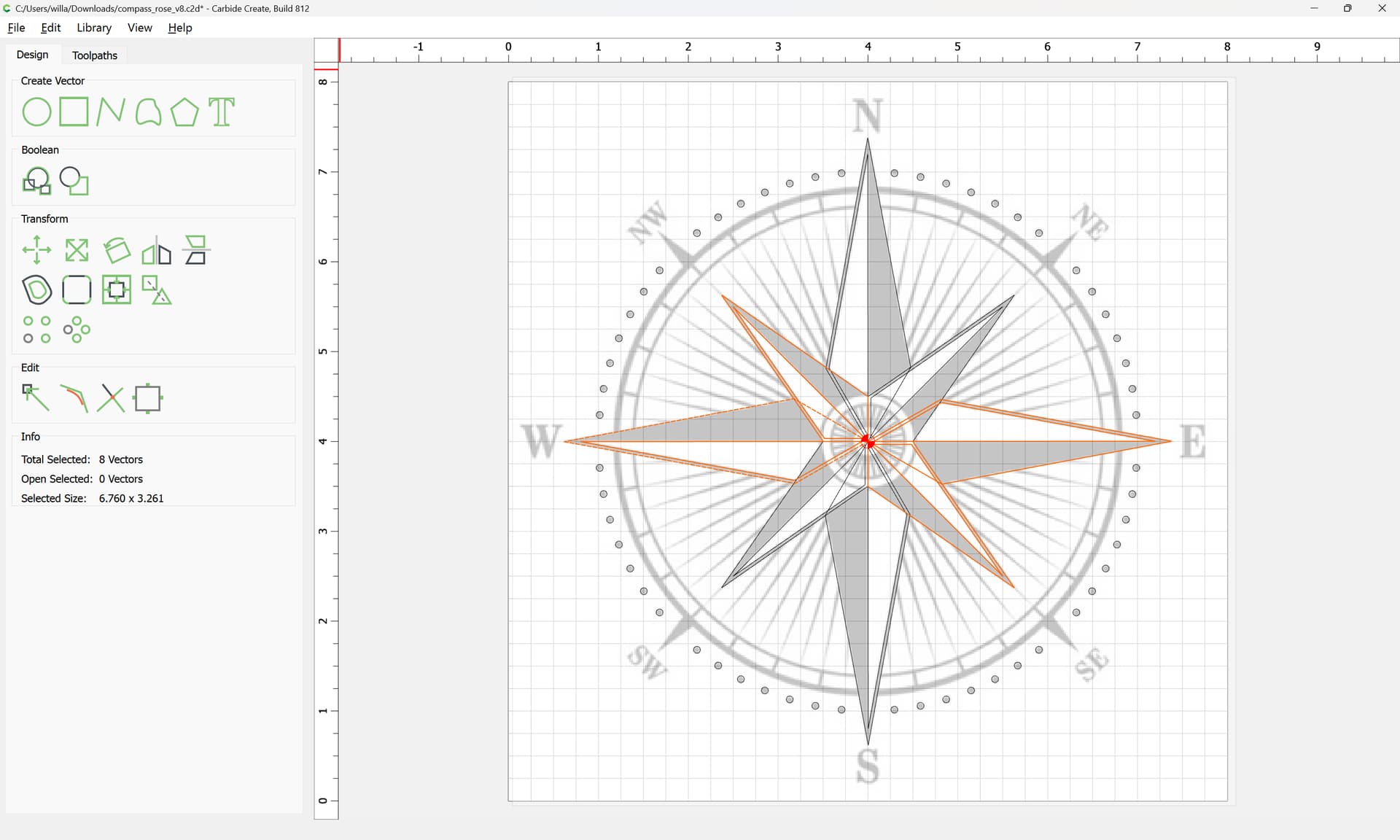
Since things are symmetrical, it will be best to draw up multiple elements to ensure that things line up as expected:

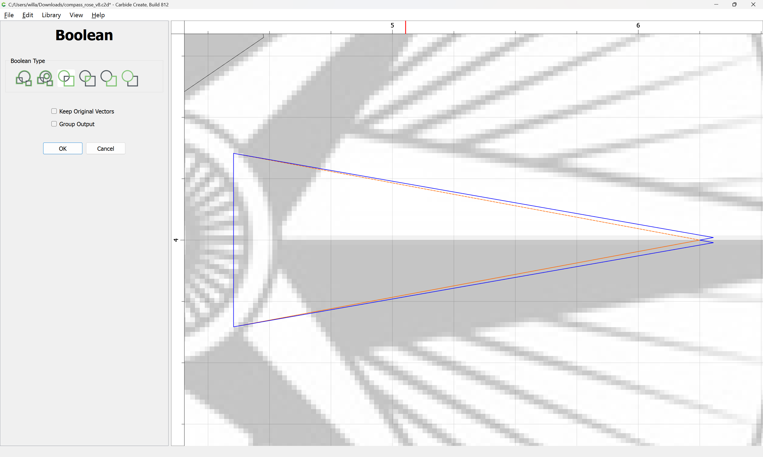
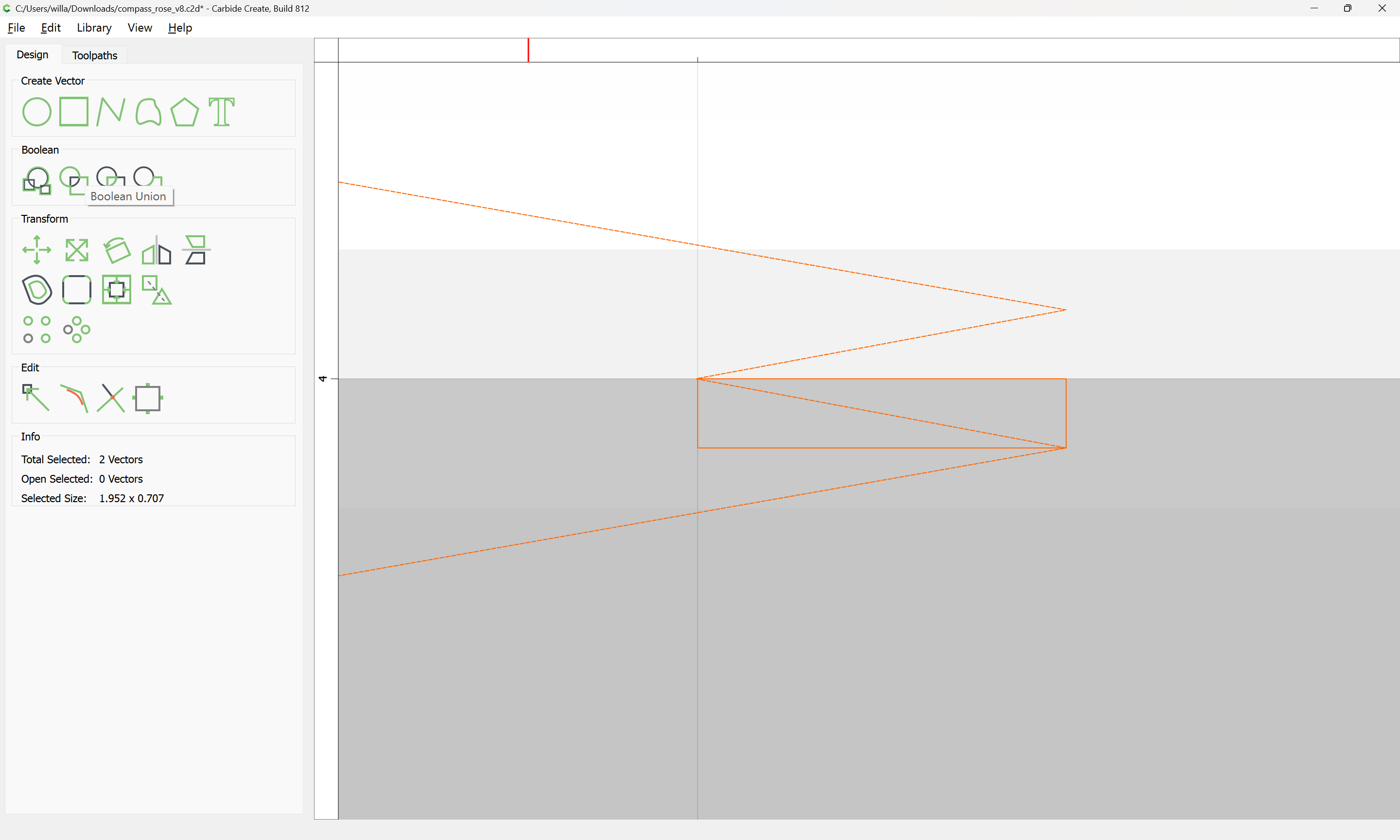
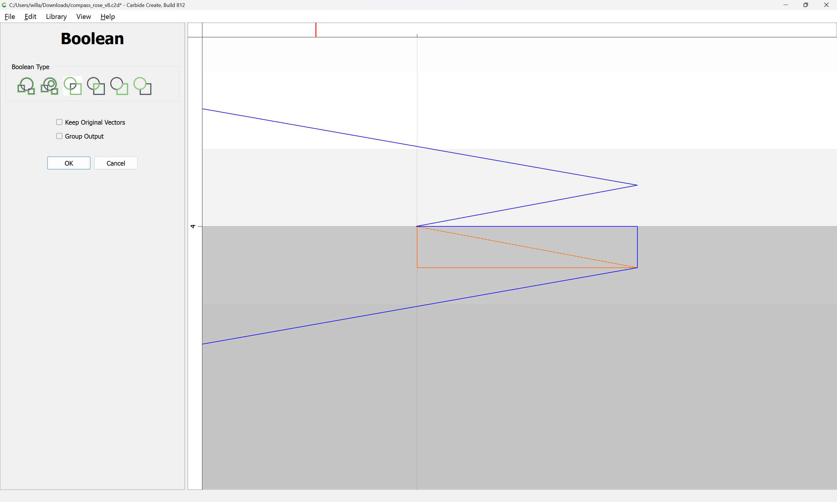
and once drawn to duplicate and flip them and Boolean Union so as to ensure that they are symmetrical:
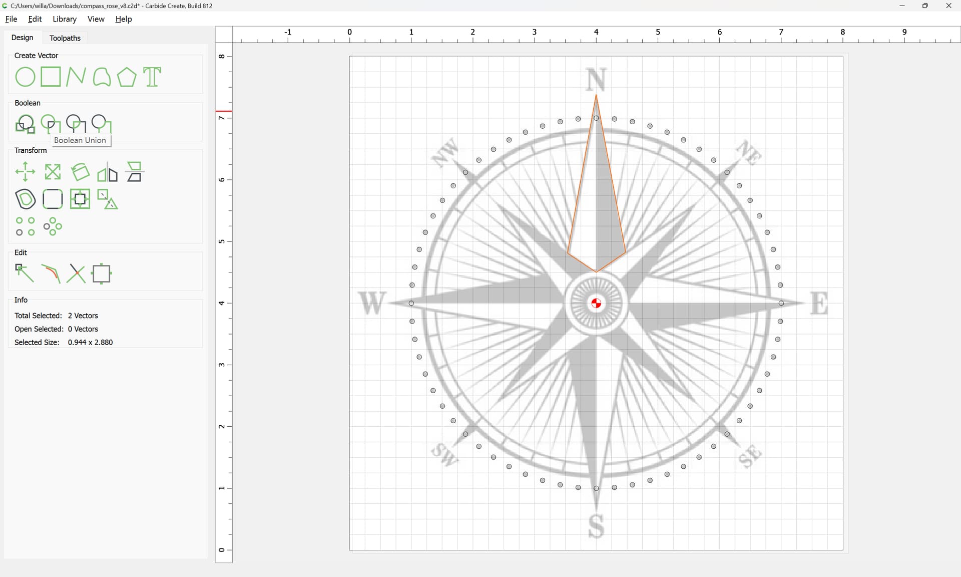
OK
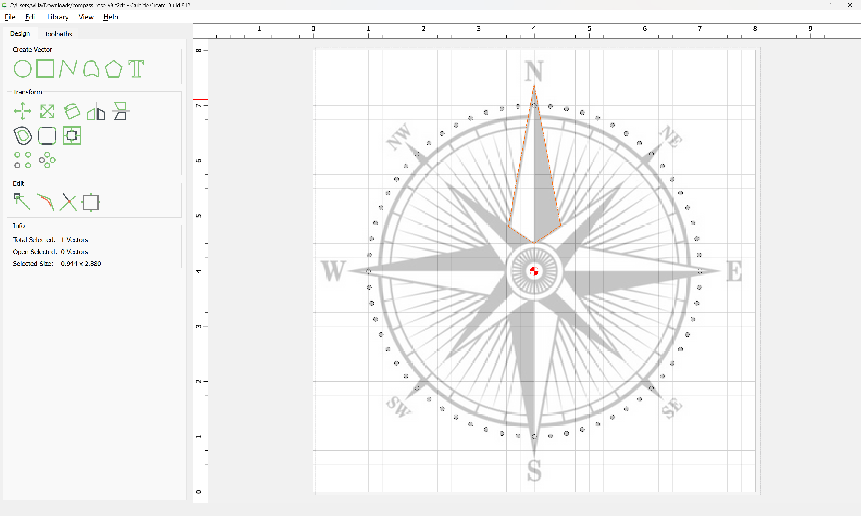
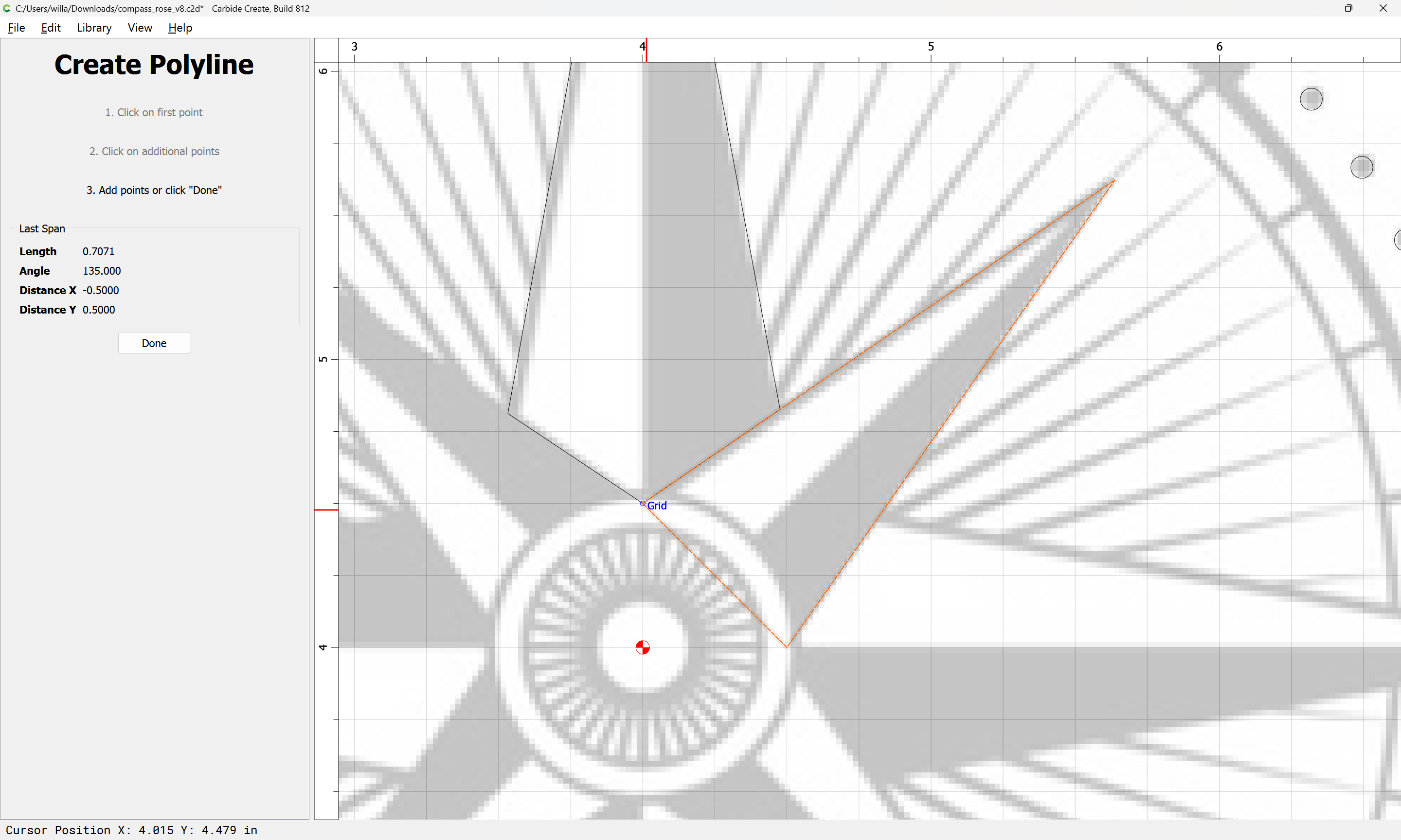
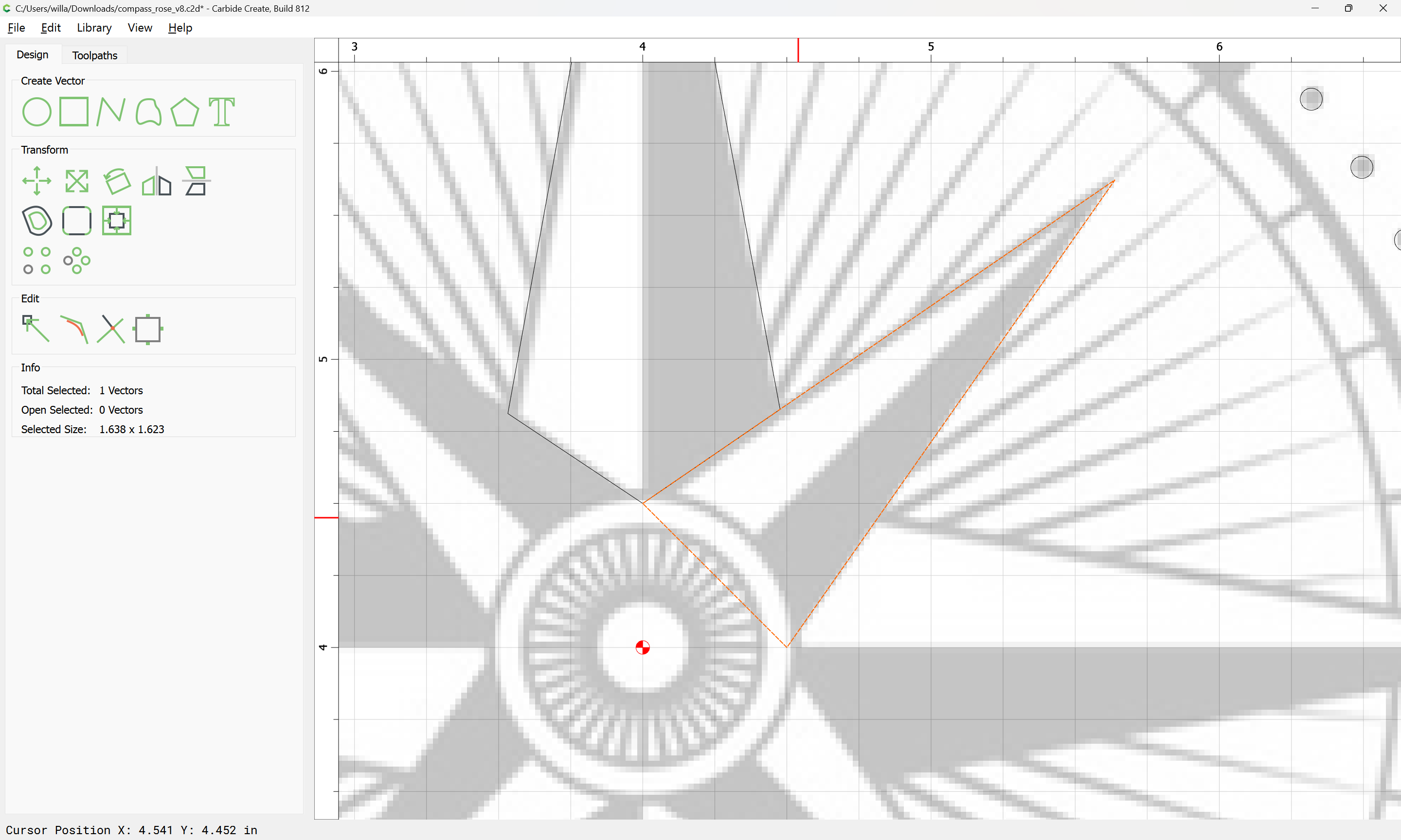
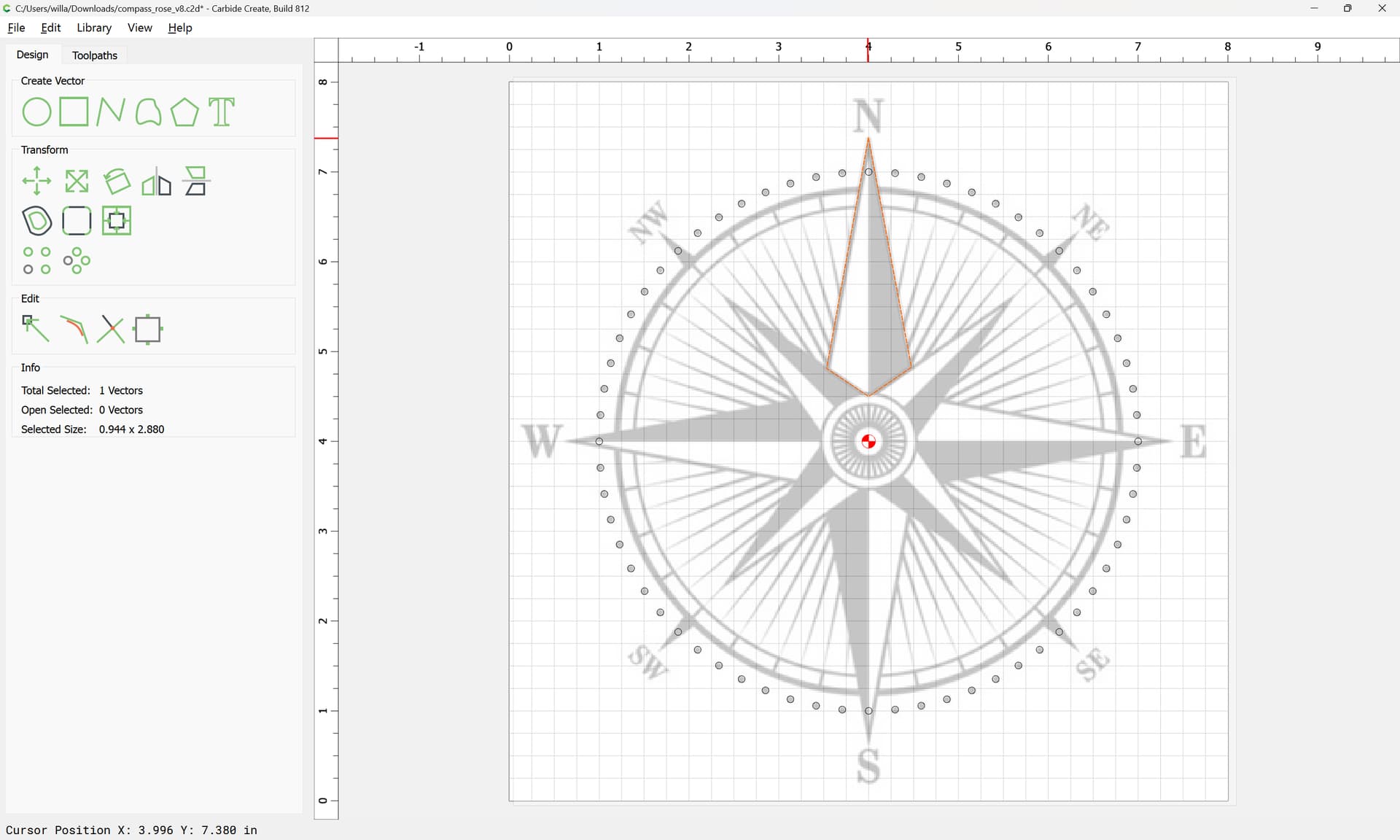
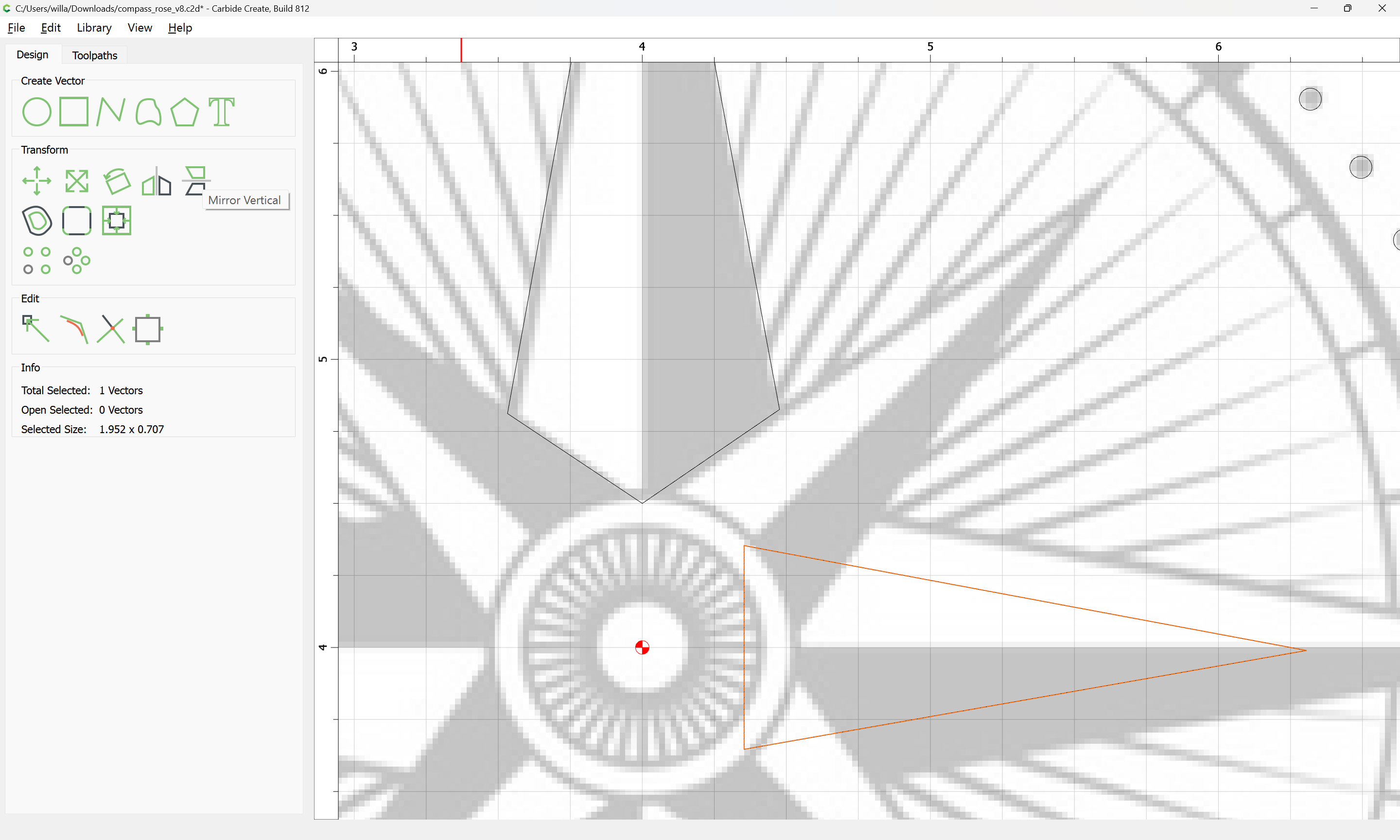
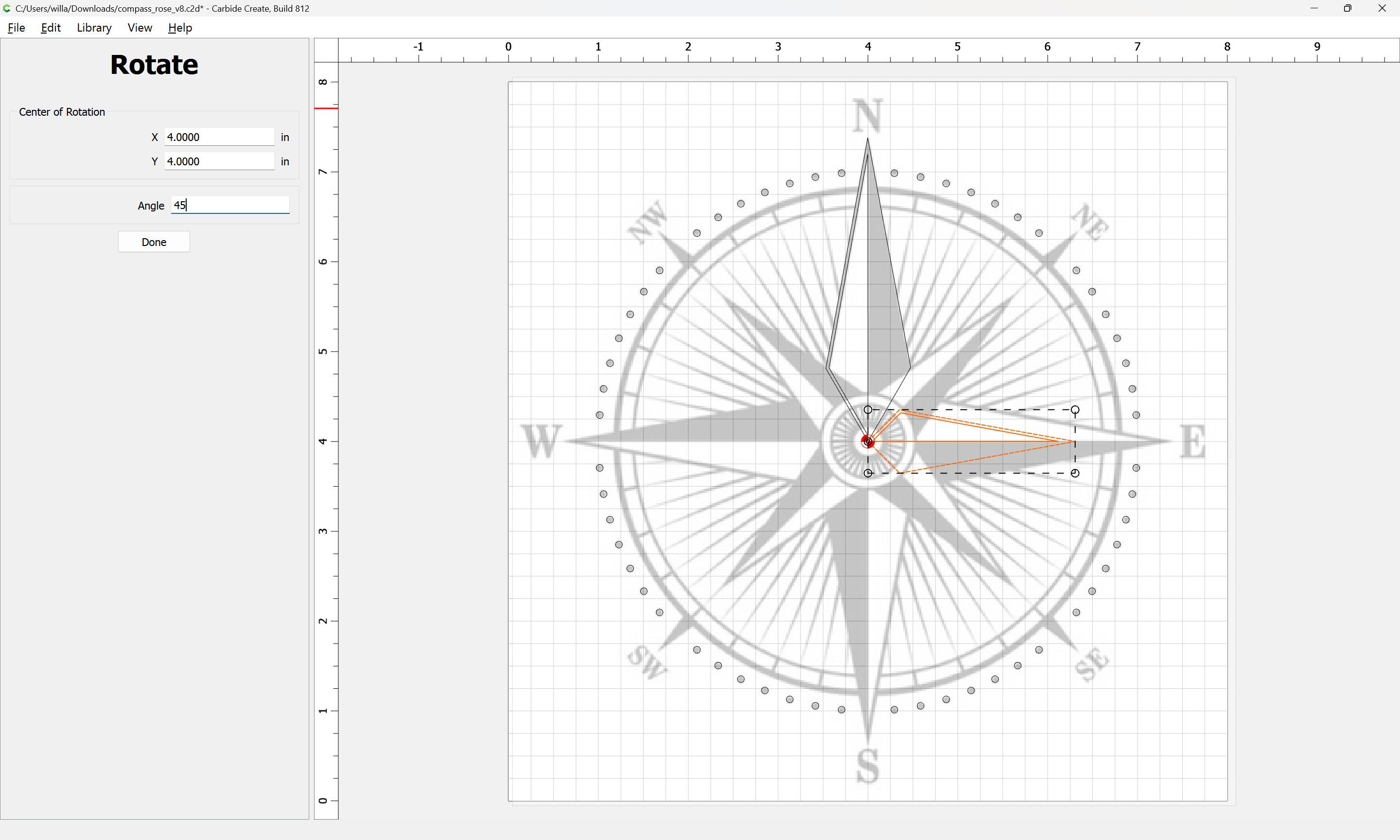
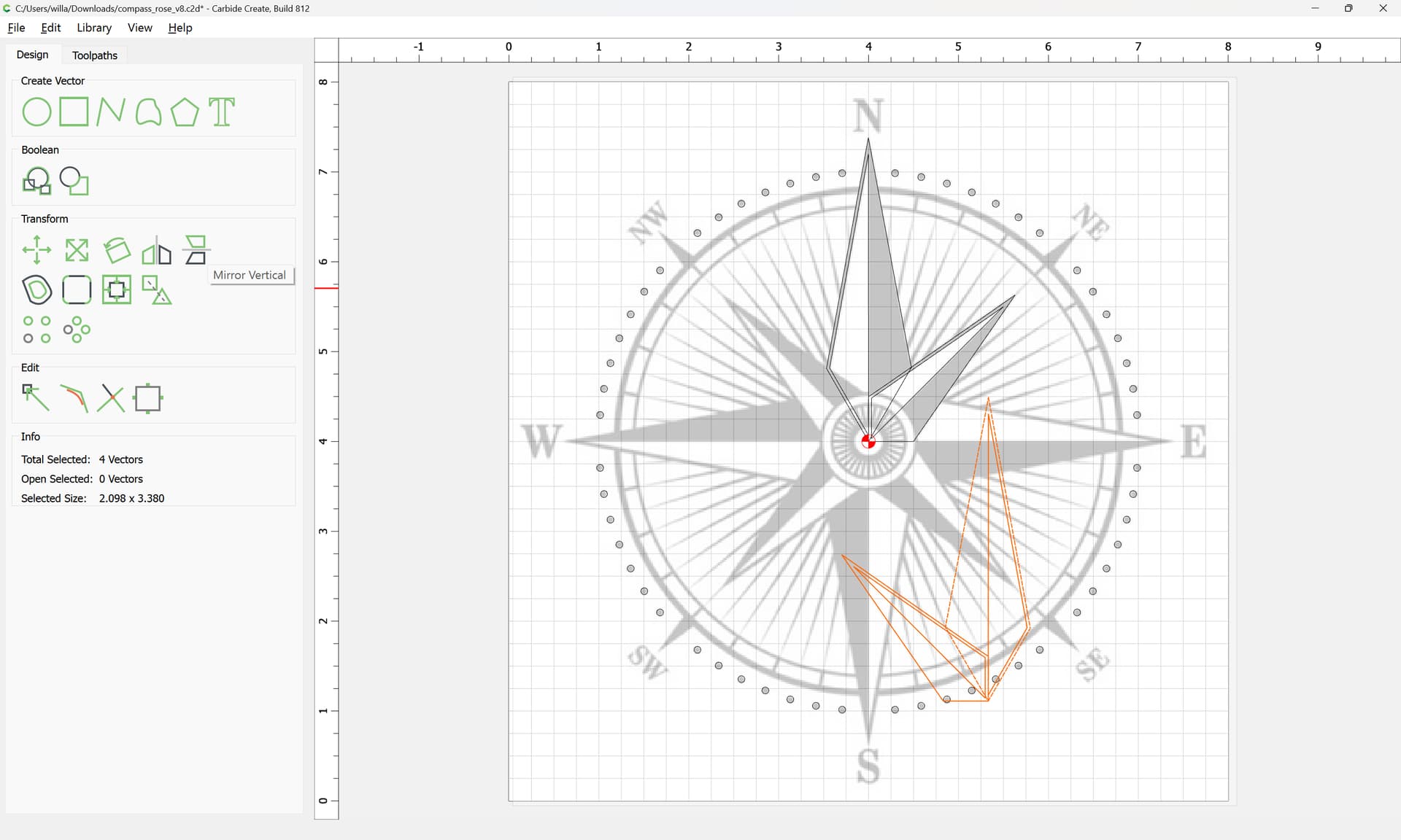
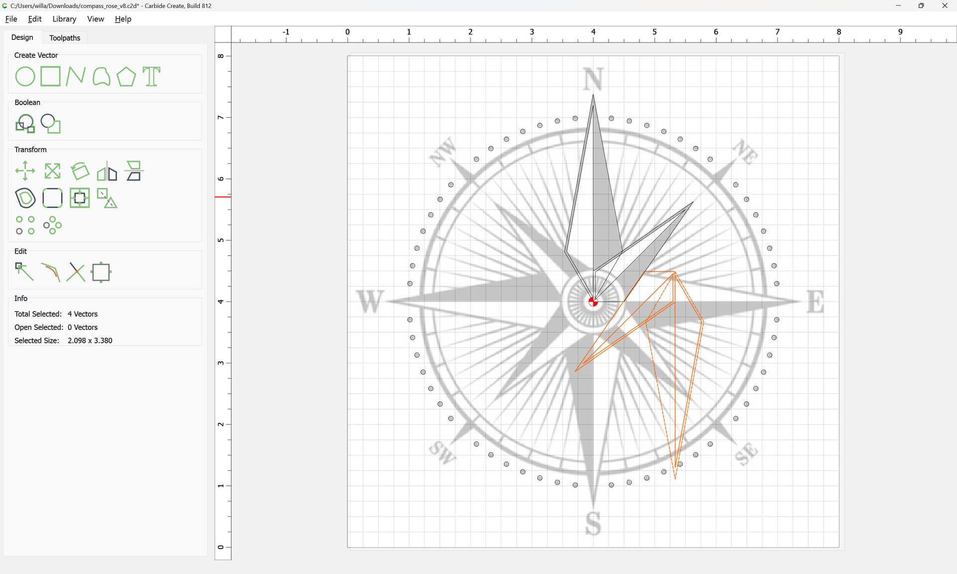
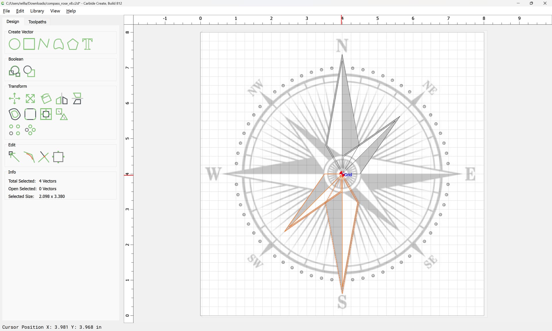
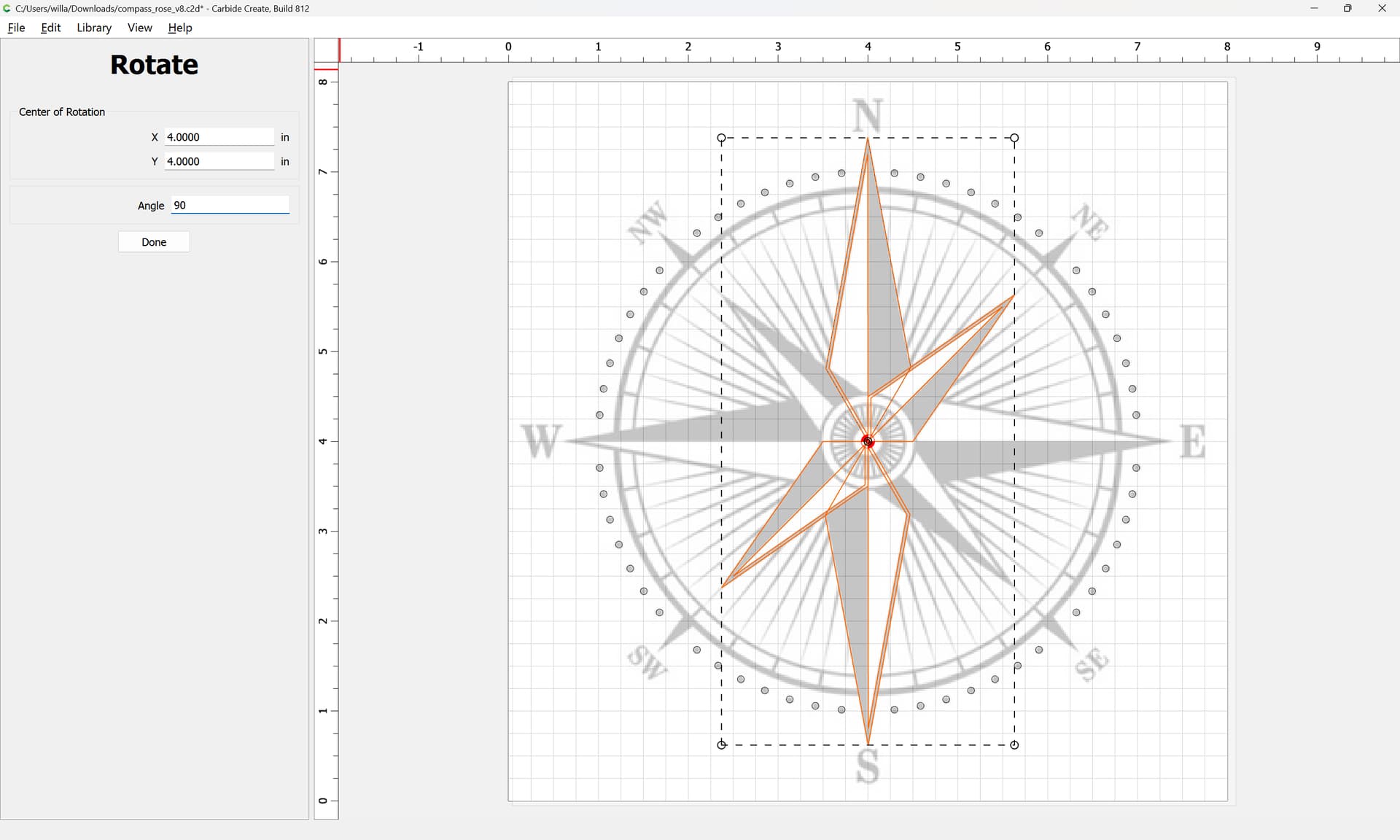
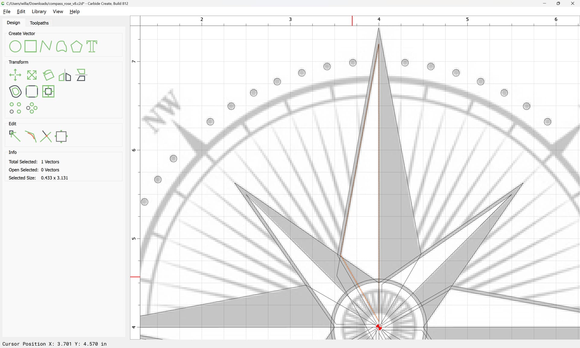
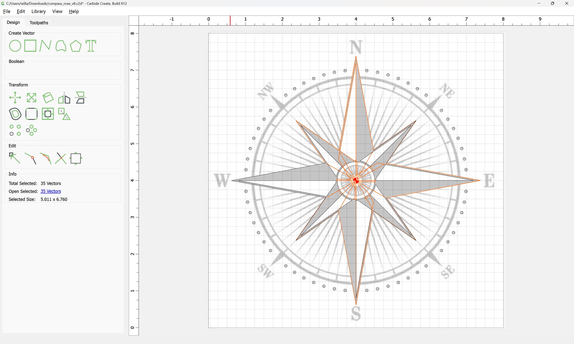
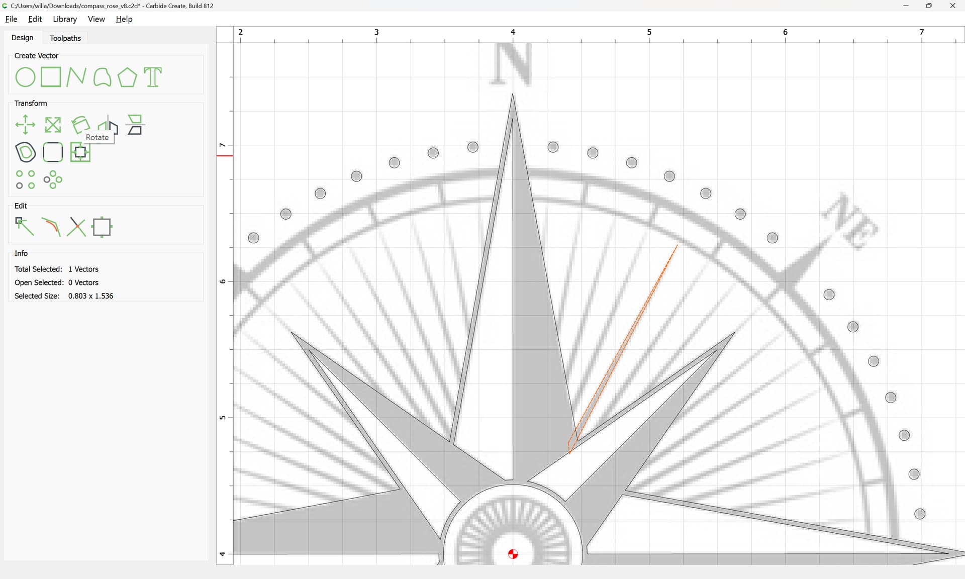
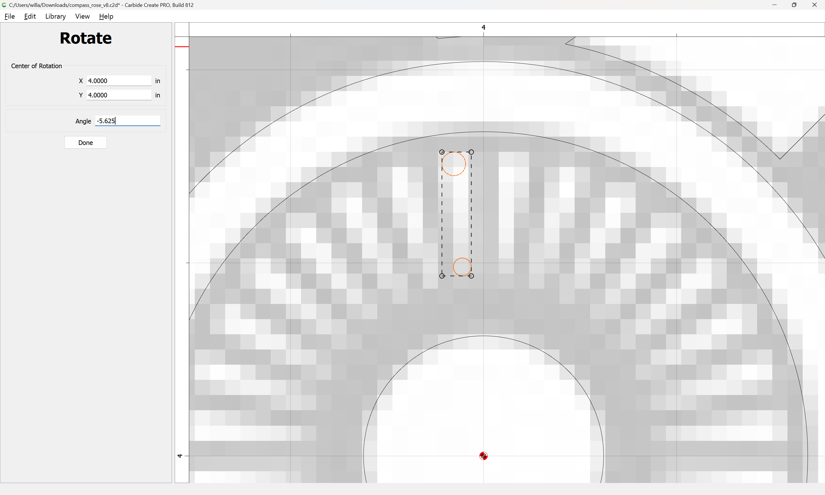
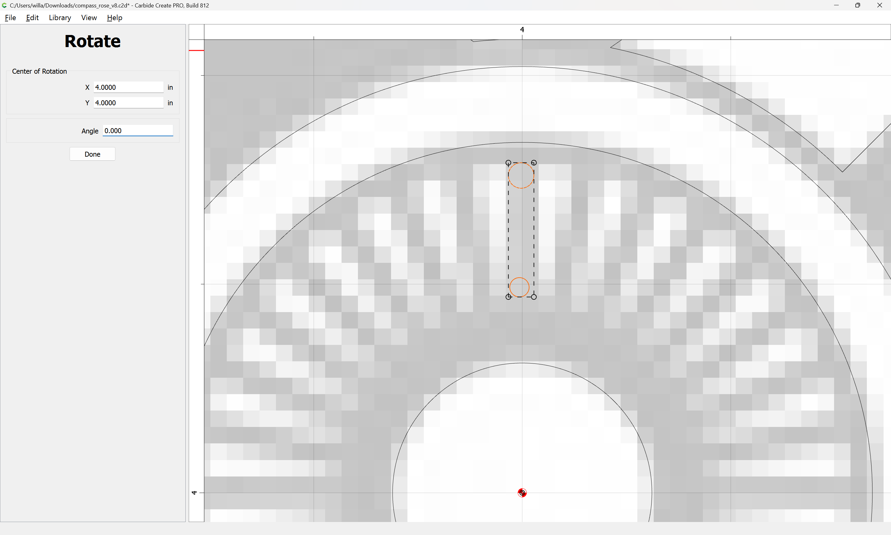
For elements which are not perfectly vertical/horizontal it will be easiest to rotate them:
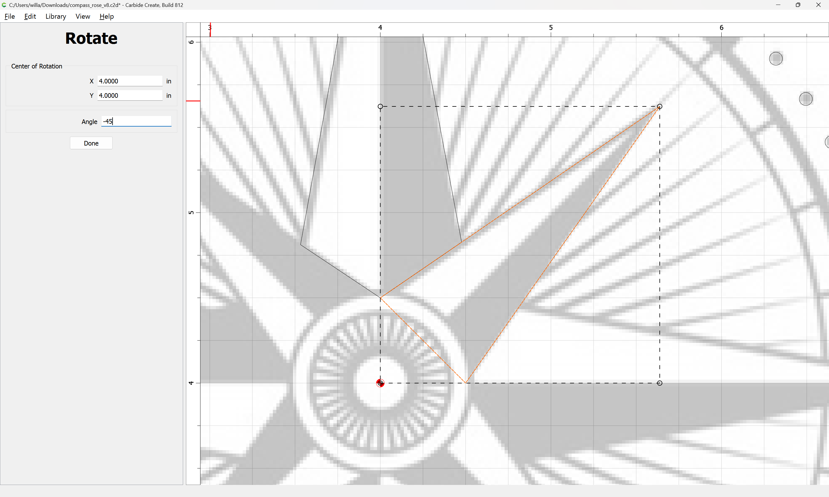
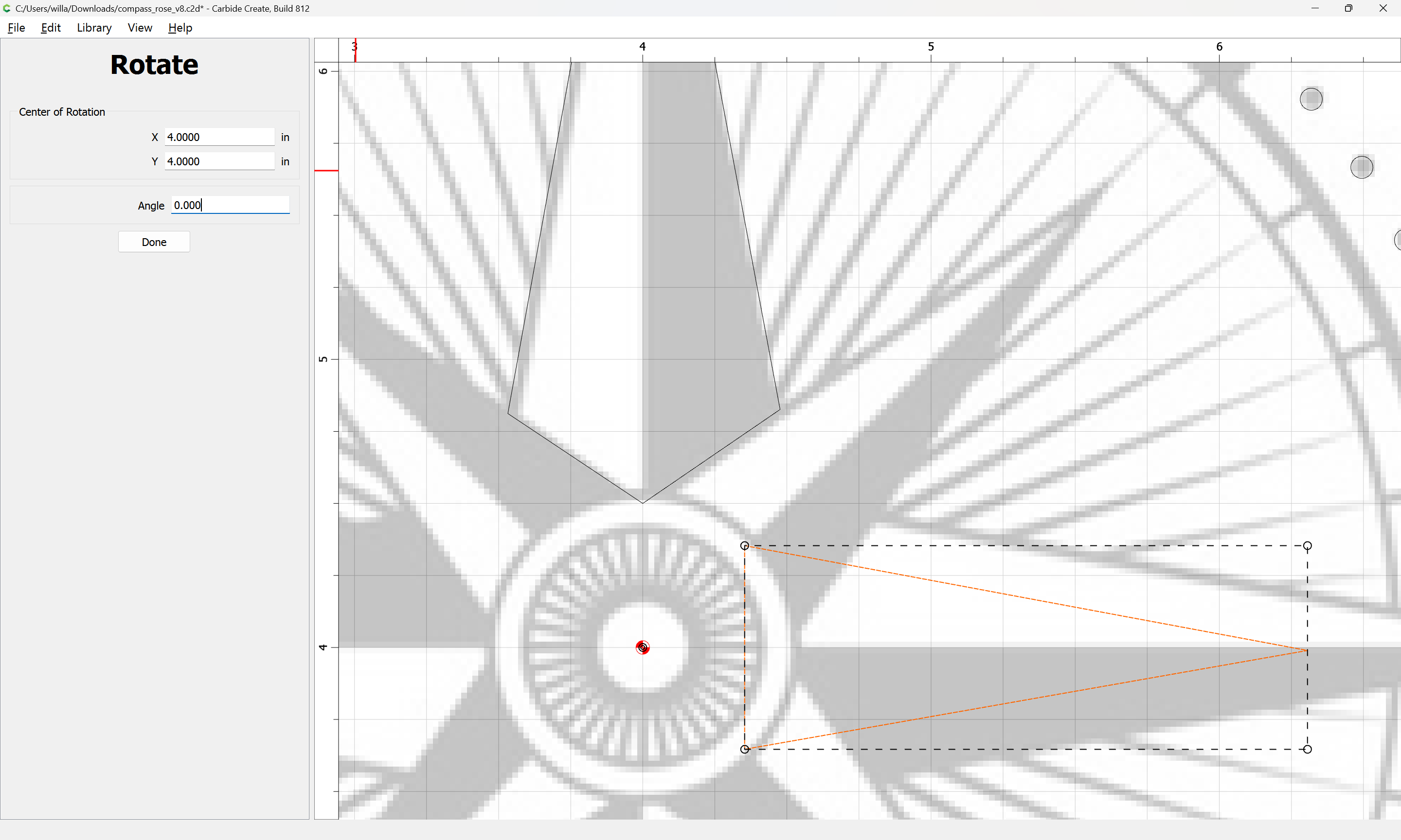
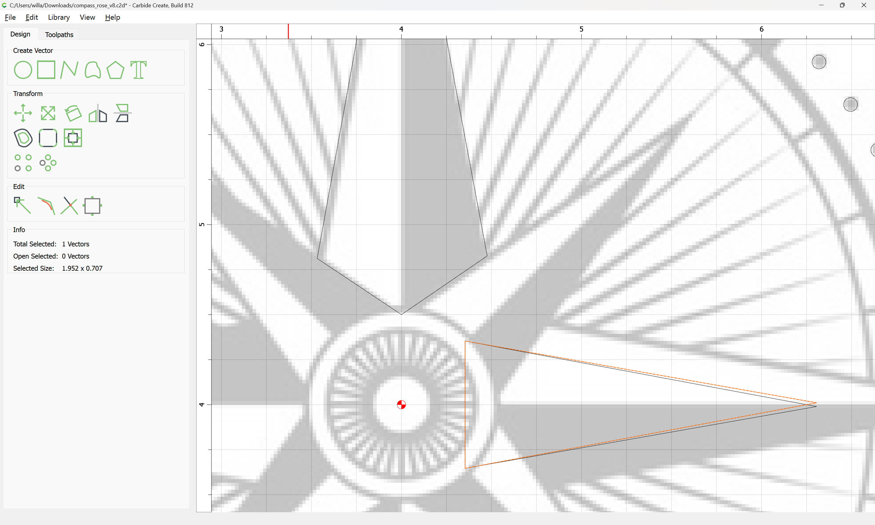
and if need be, to draw in additional geometry and edit, but this will be easier after unioning:
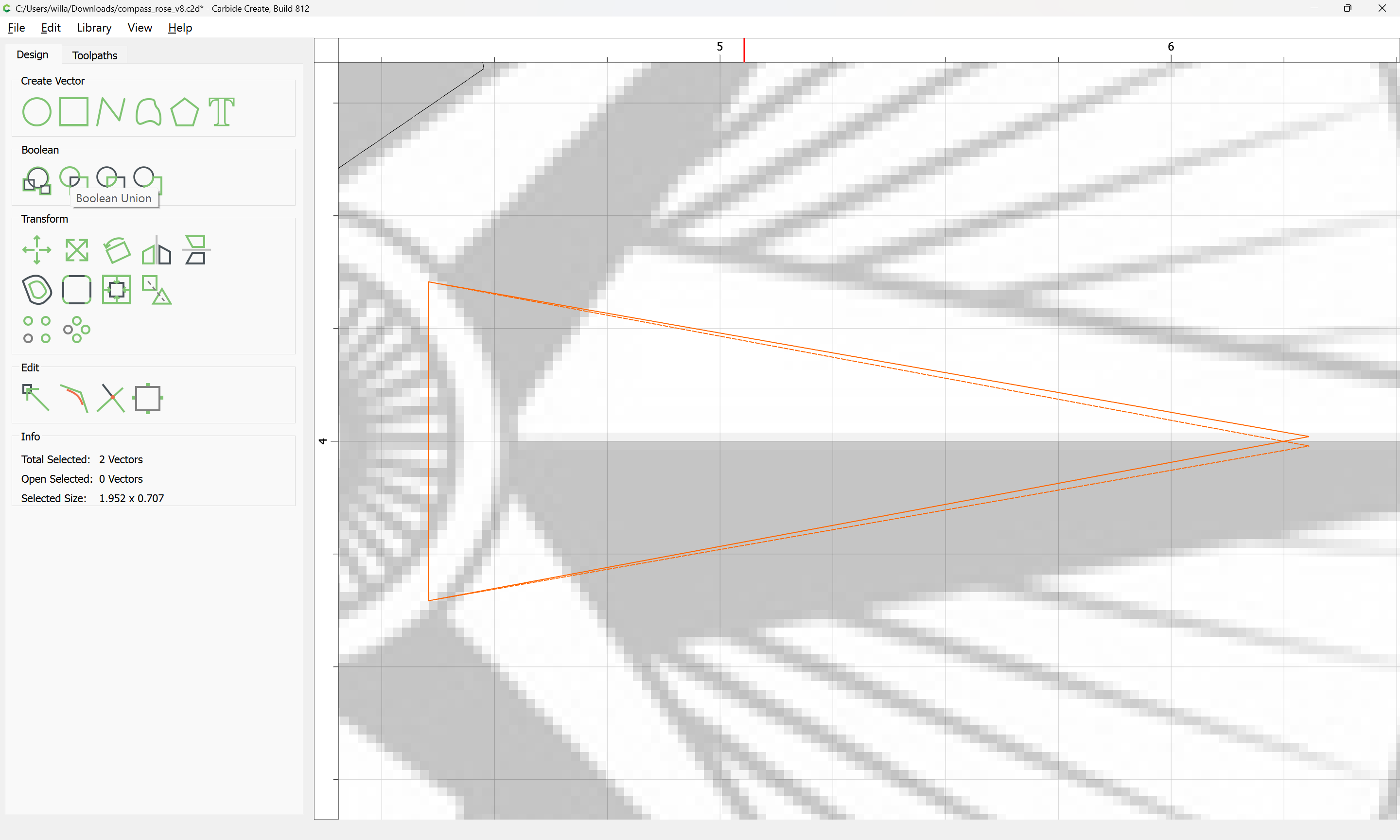
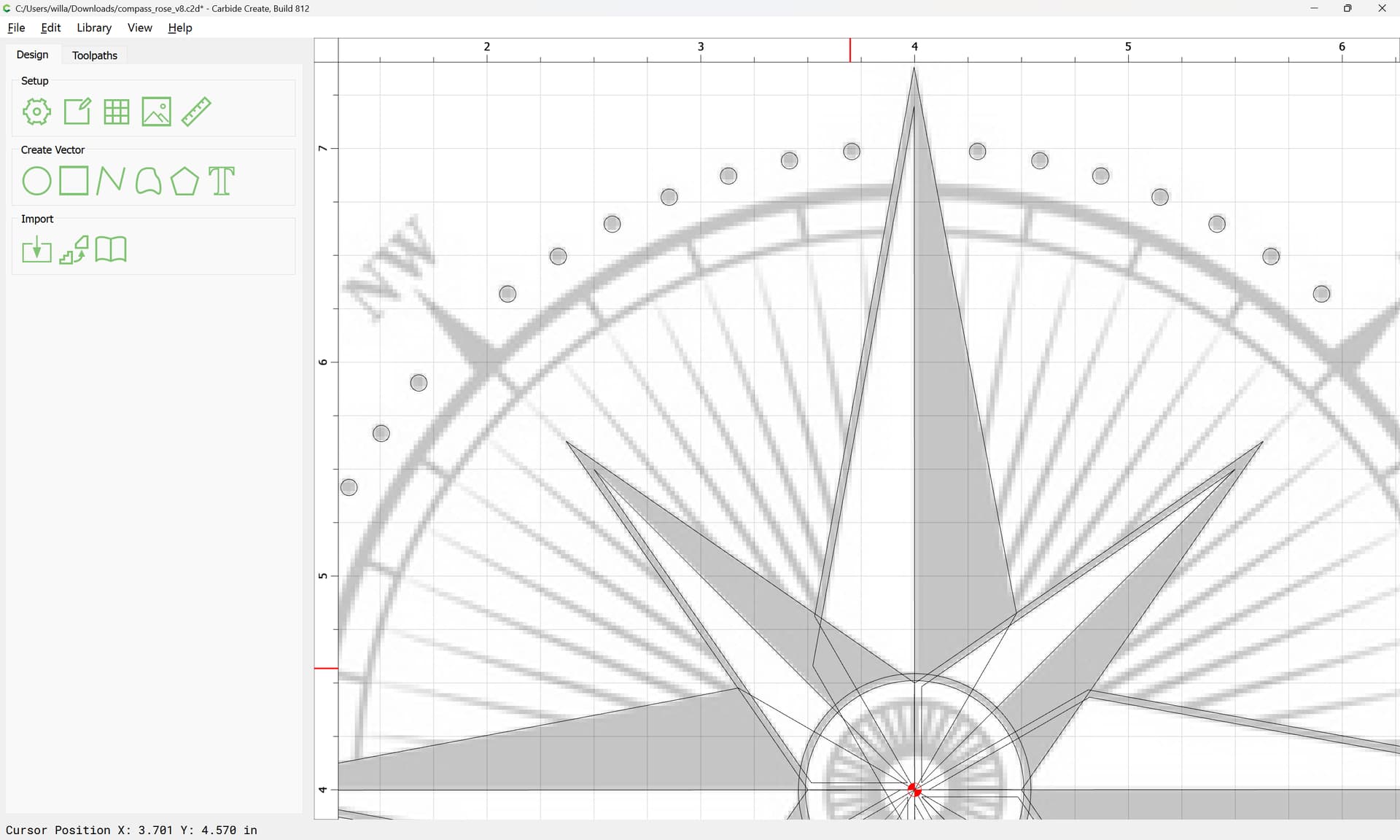
OK
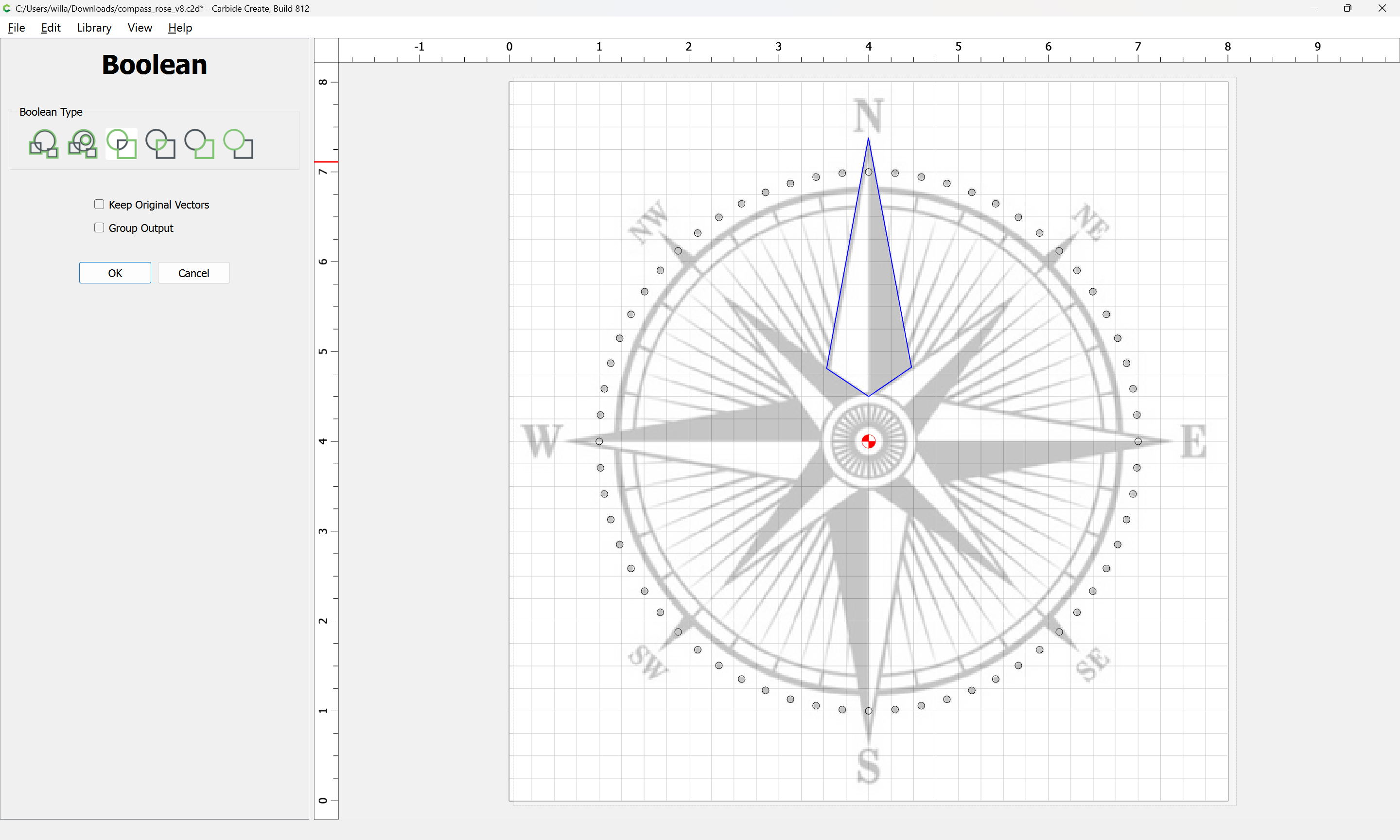
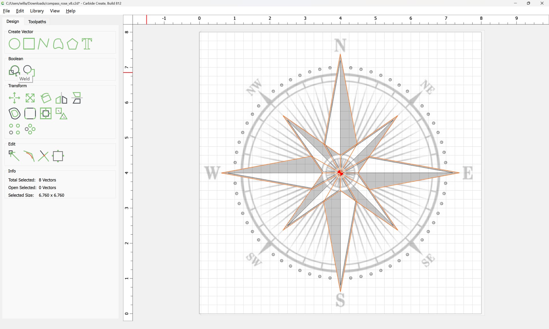
If this is then unioned:
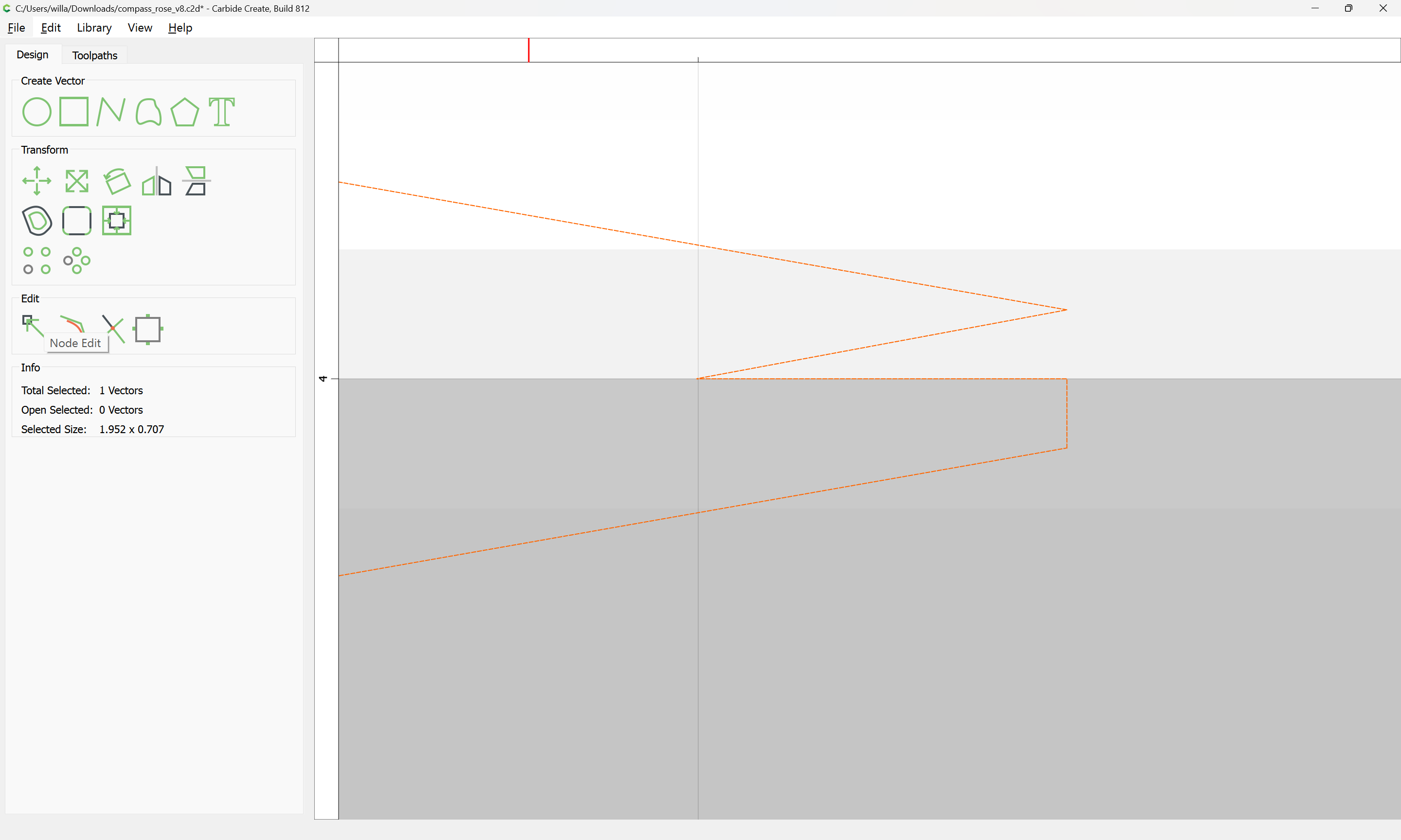
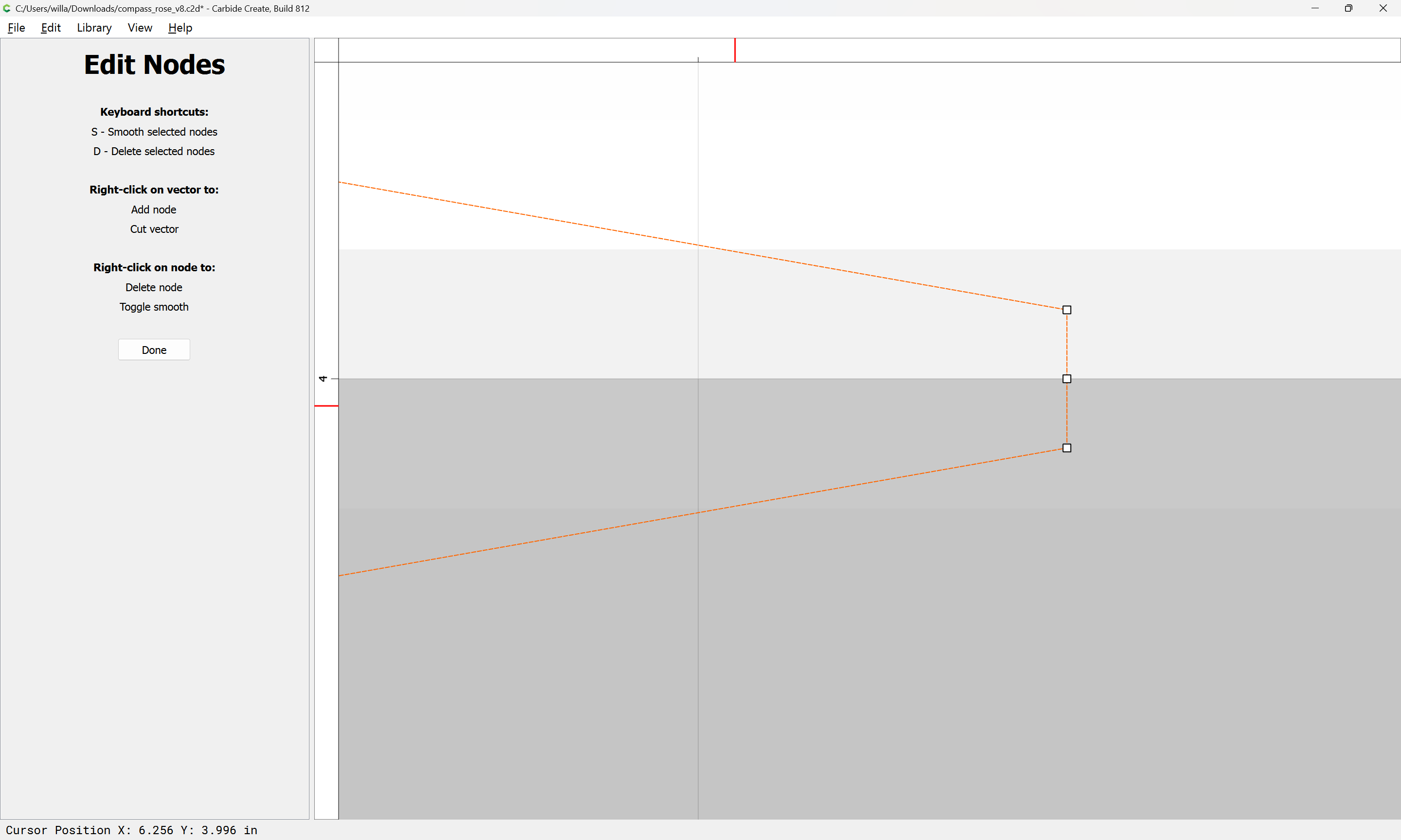
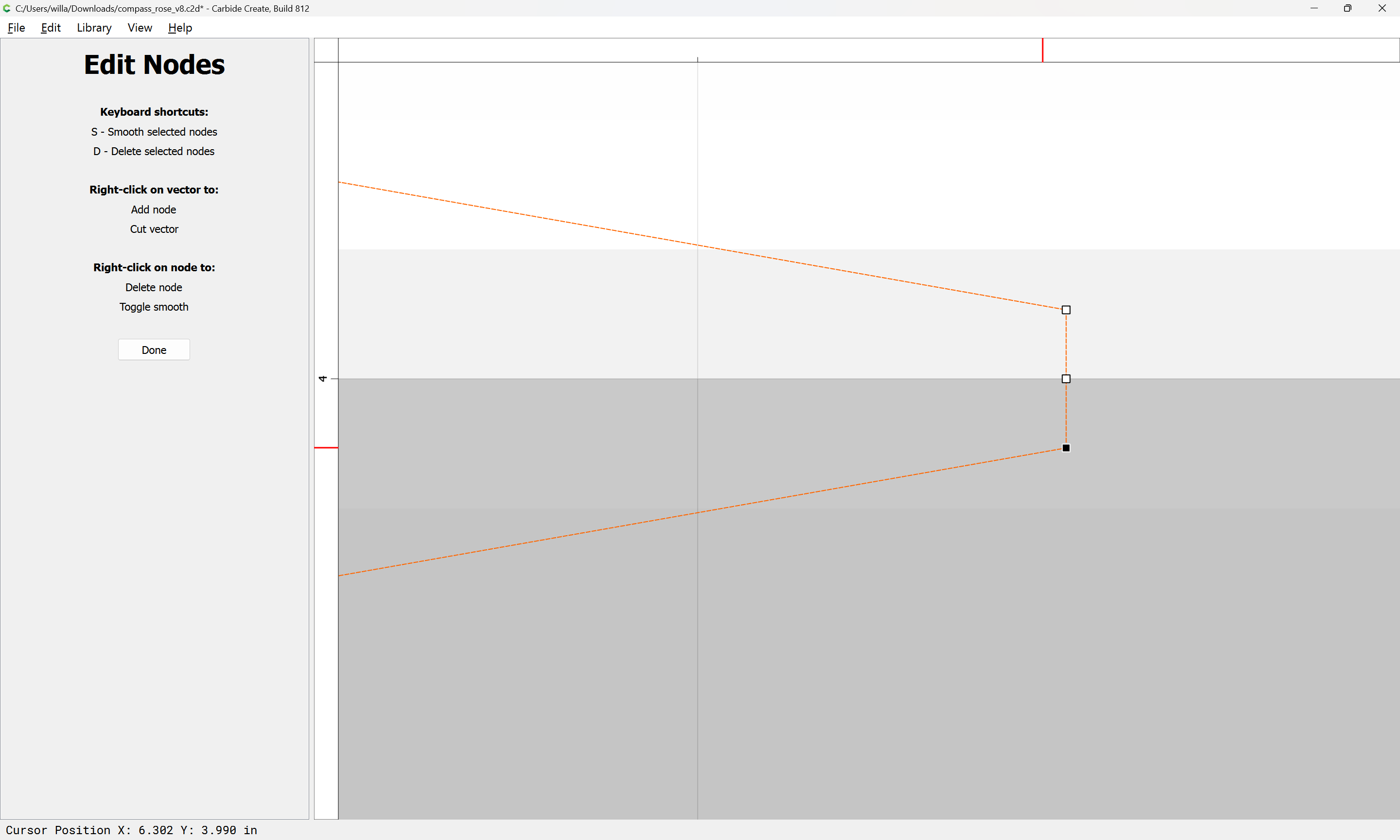
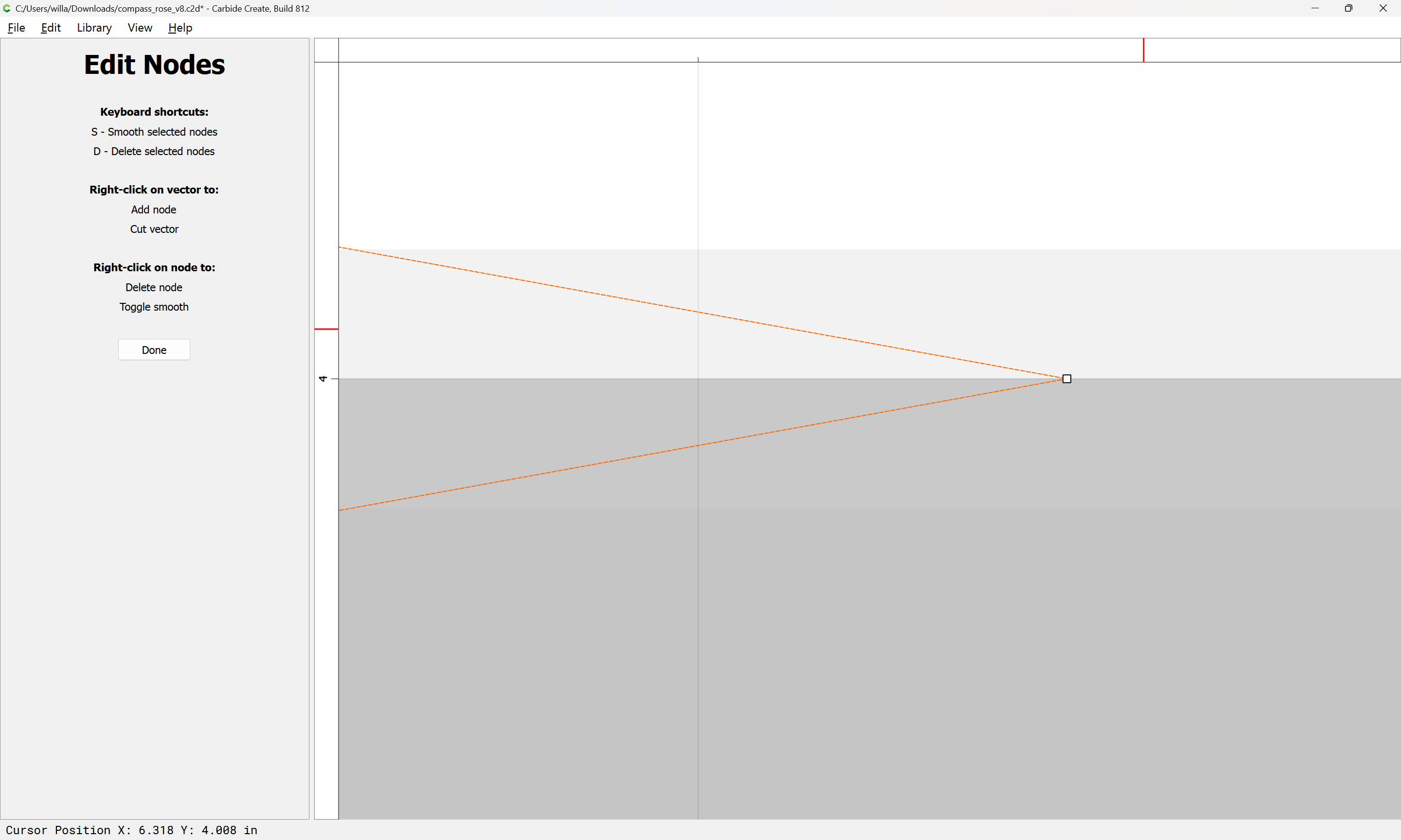
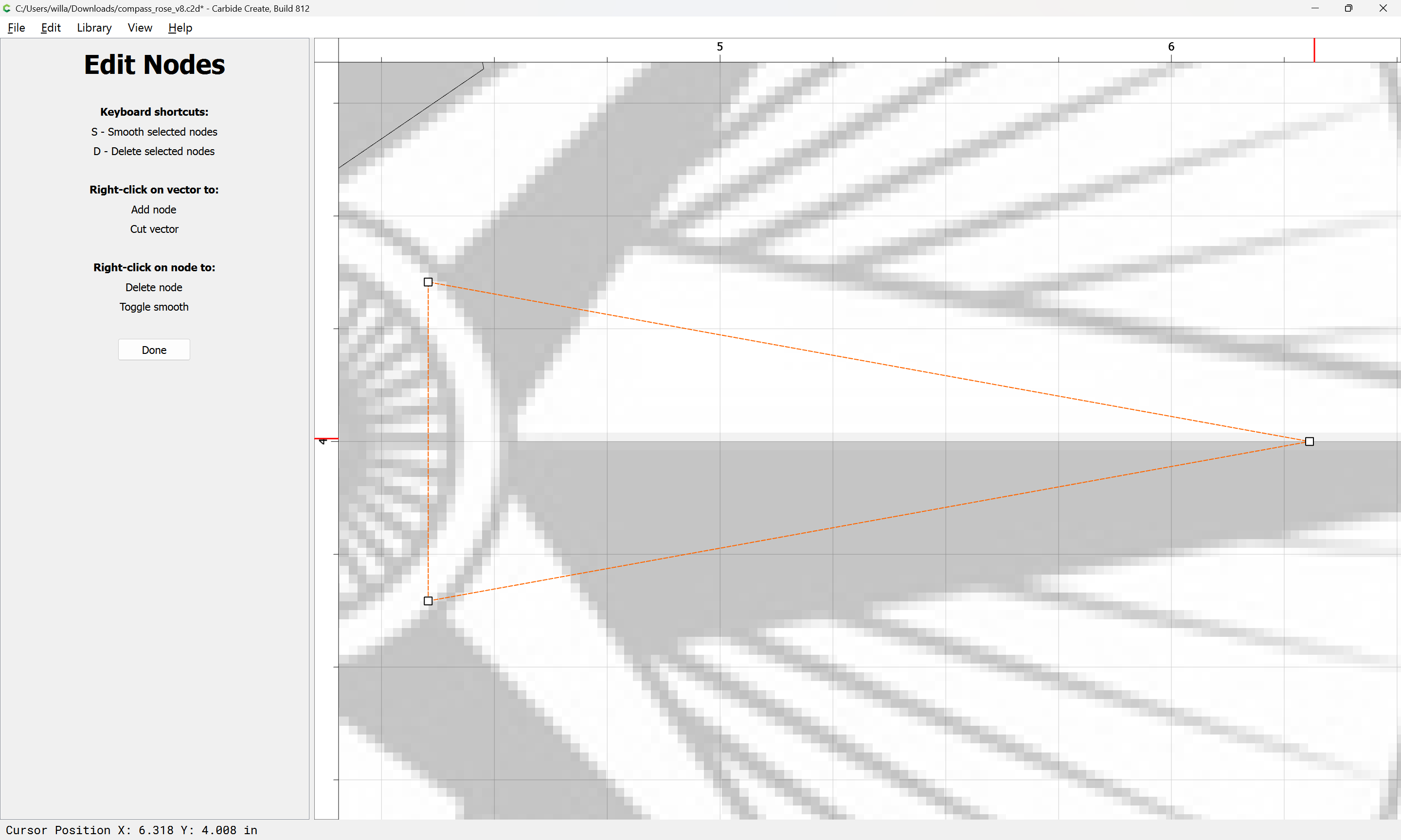
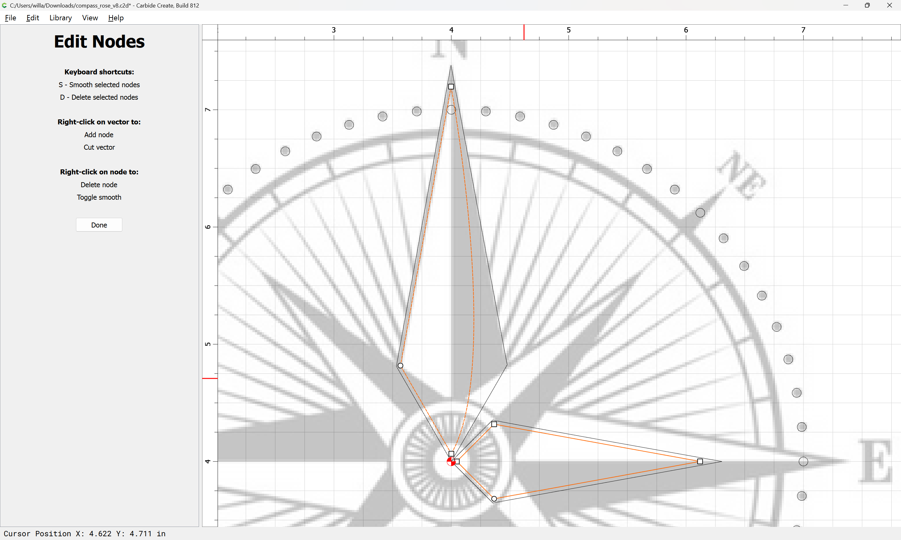
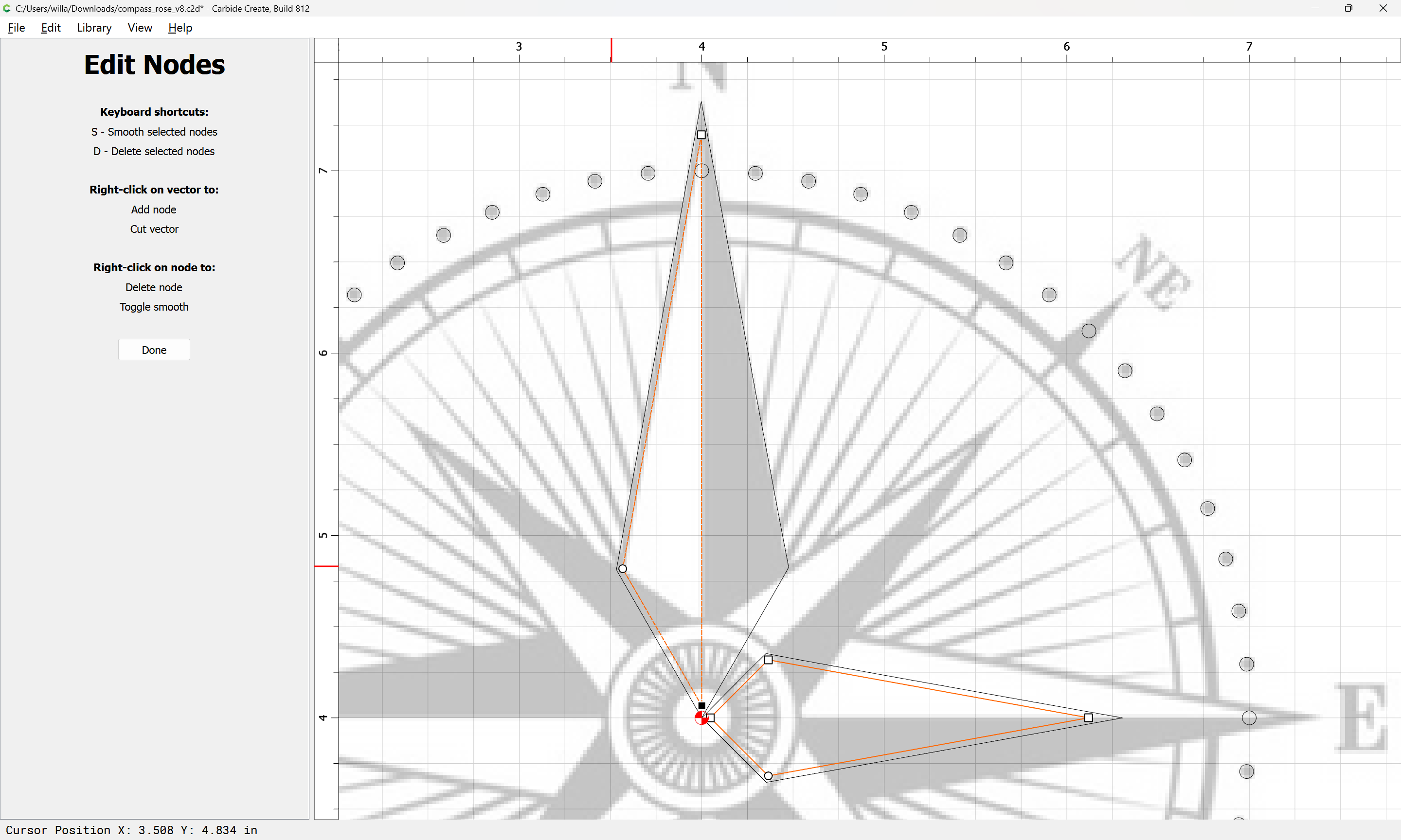
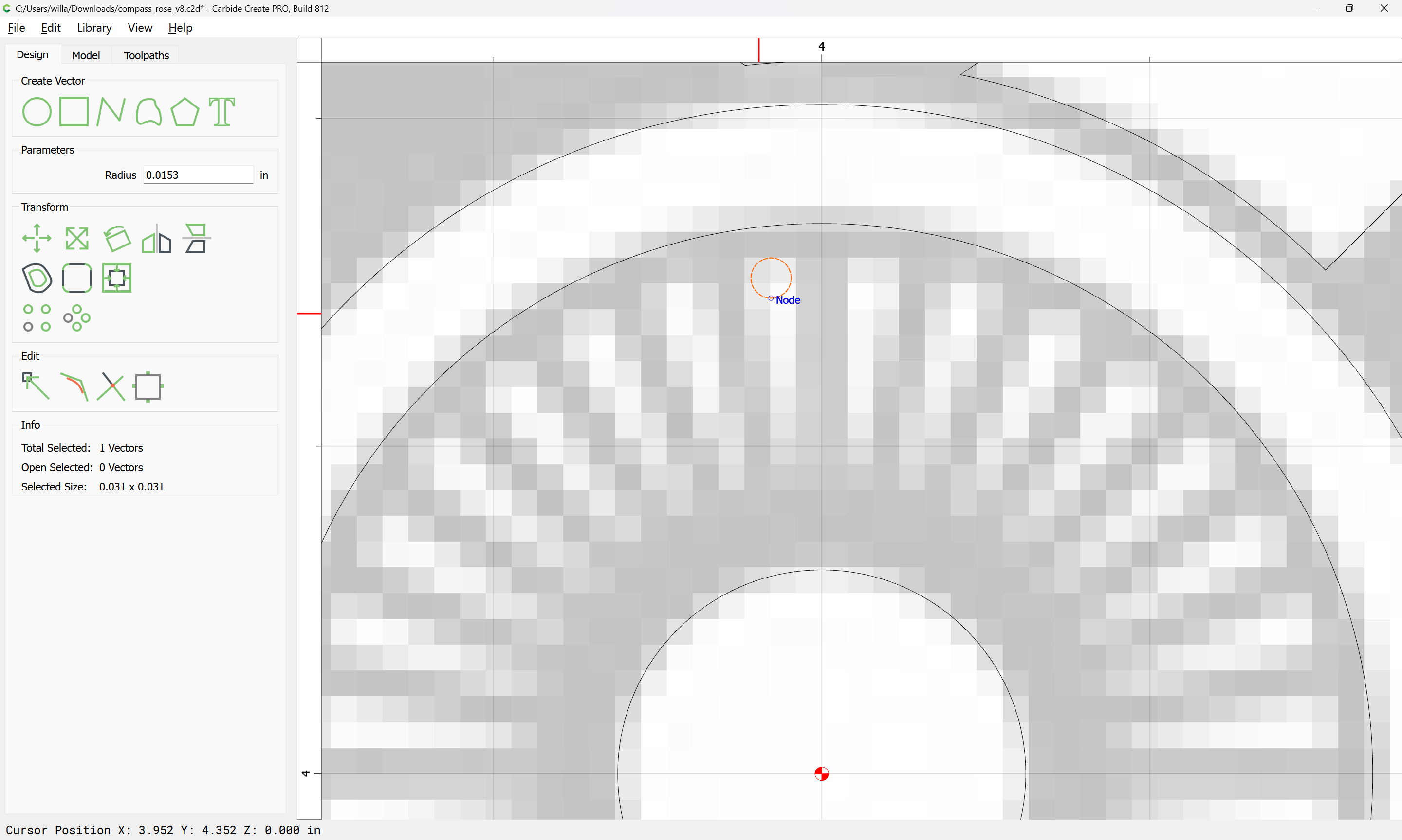
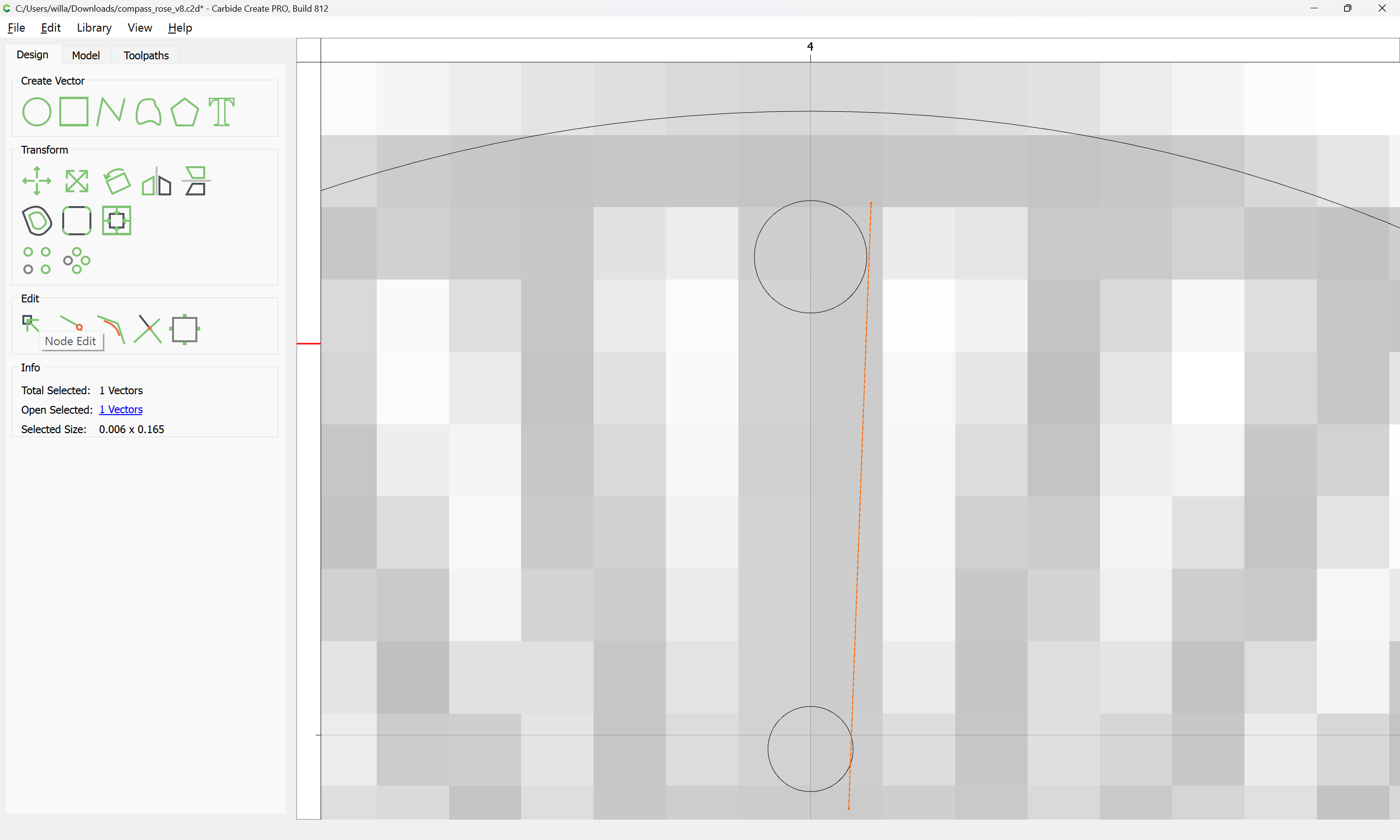
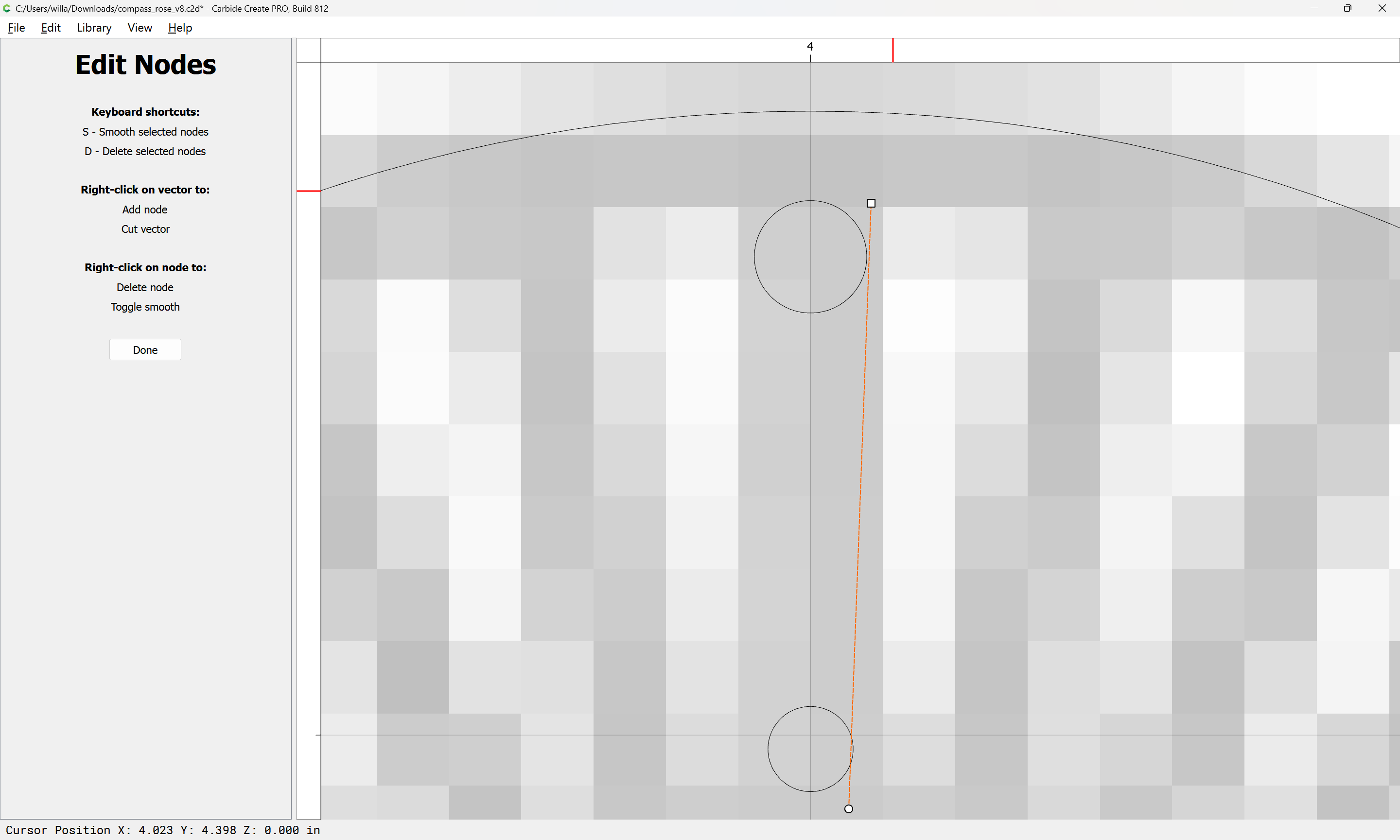
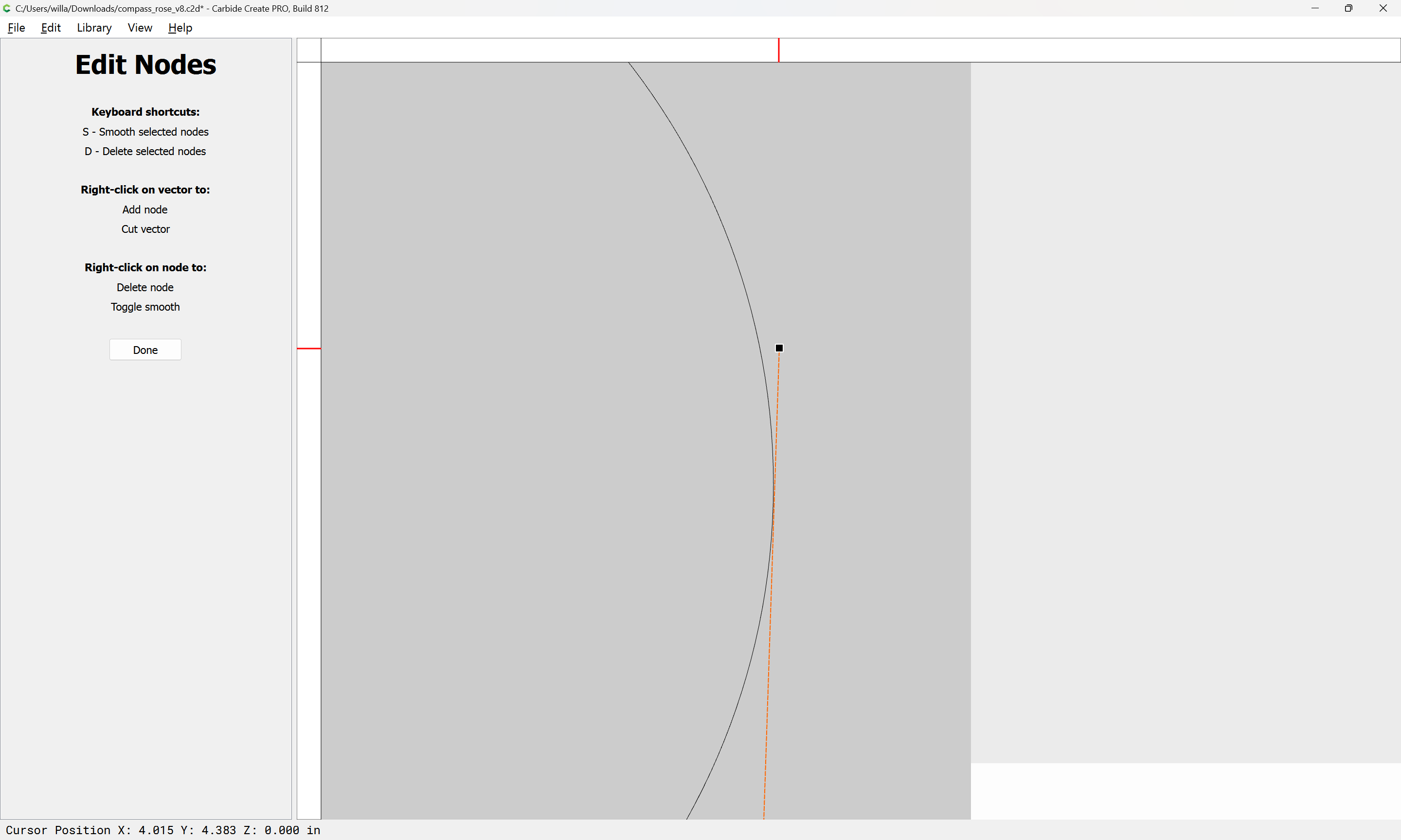
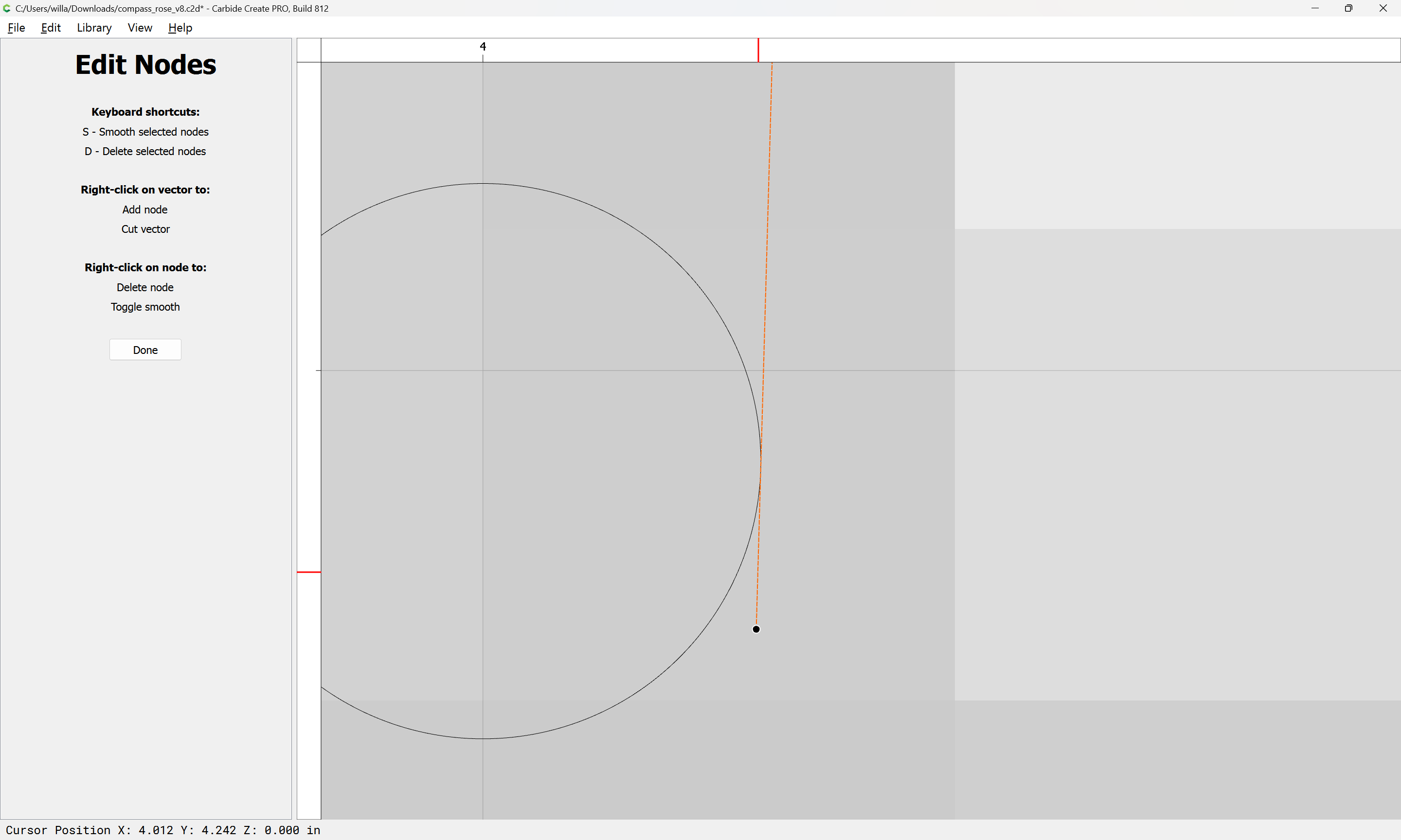
It is then trivial to use Node Editing to arrive at a symmetrical result:
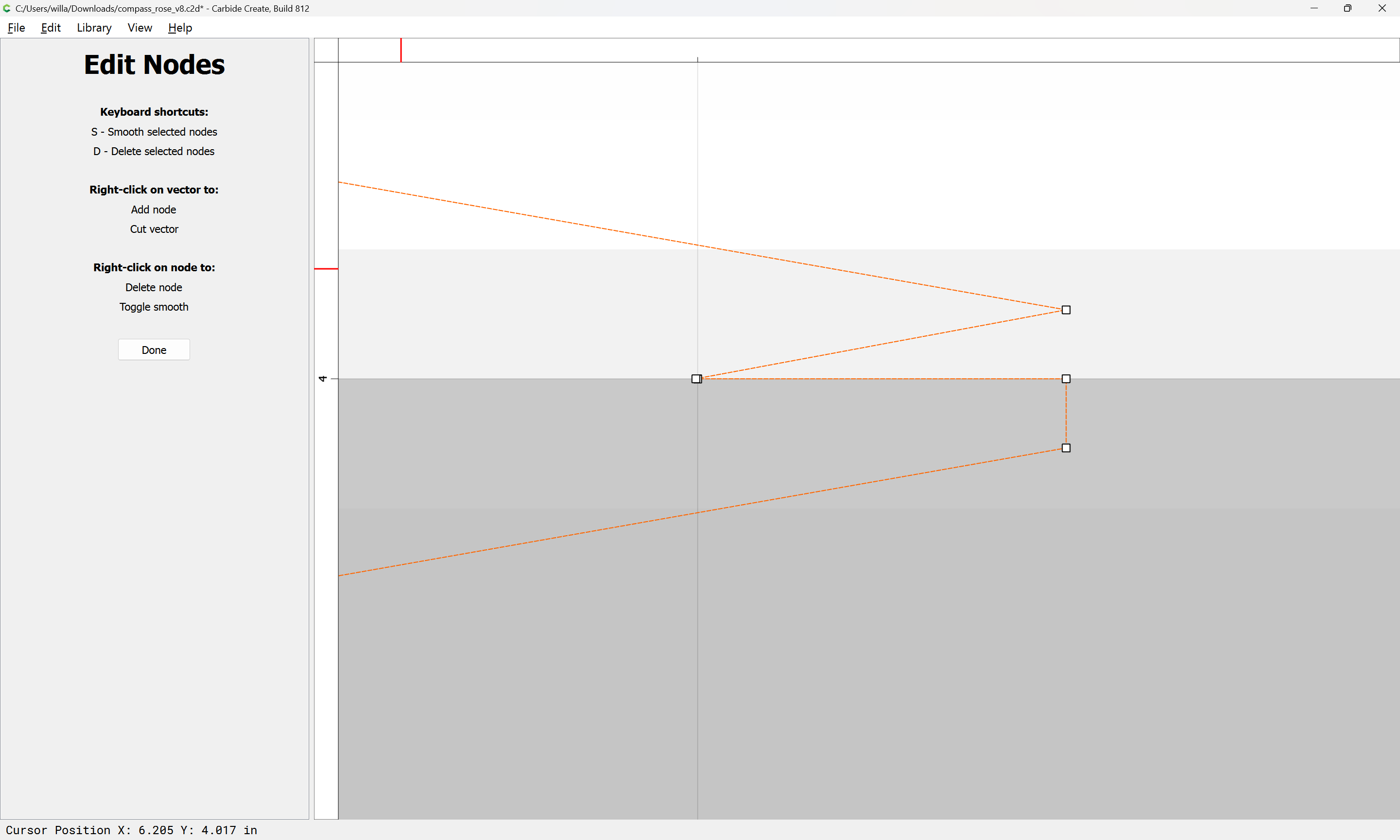
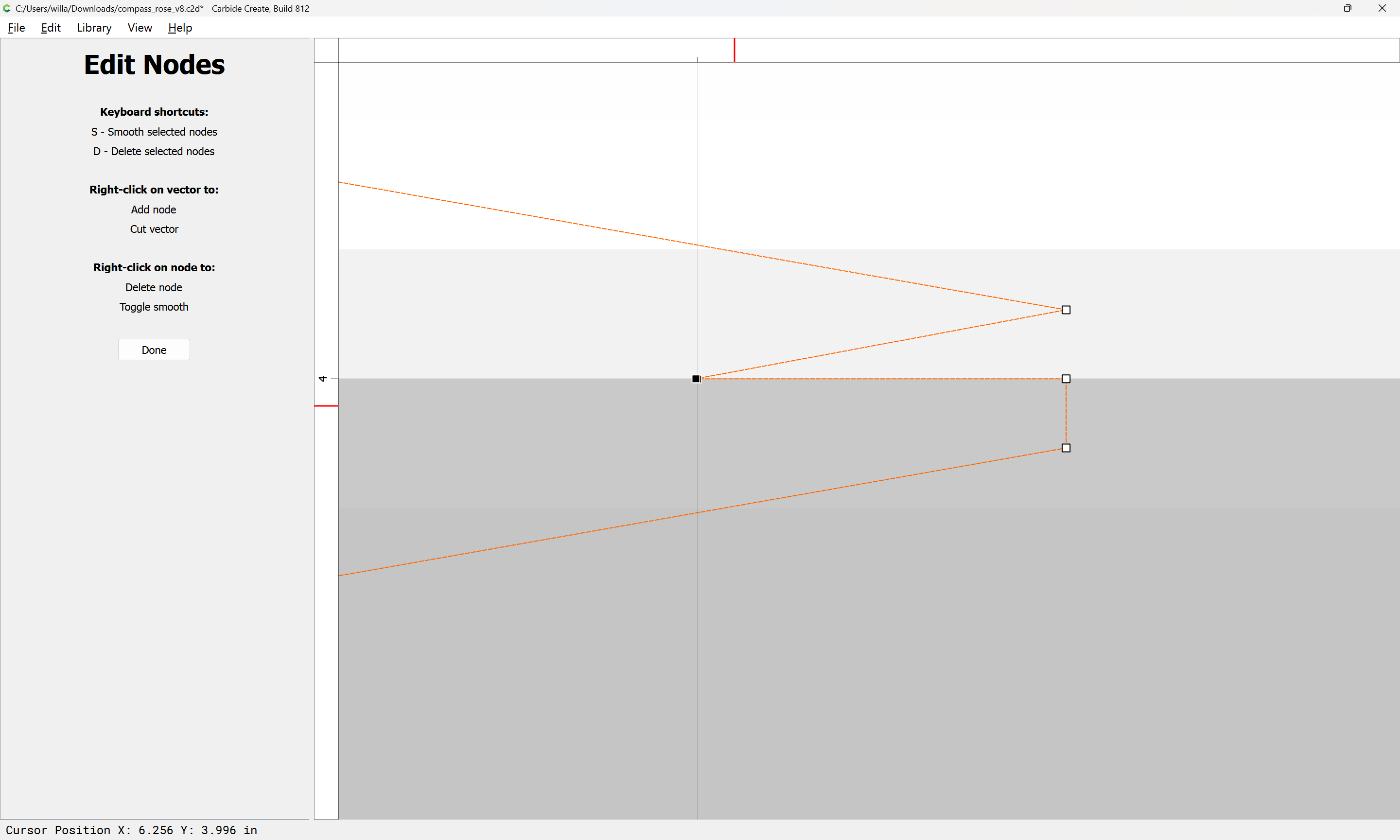
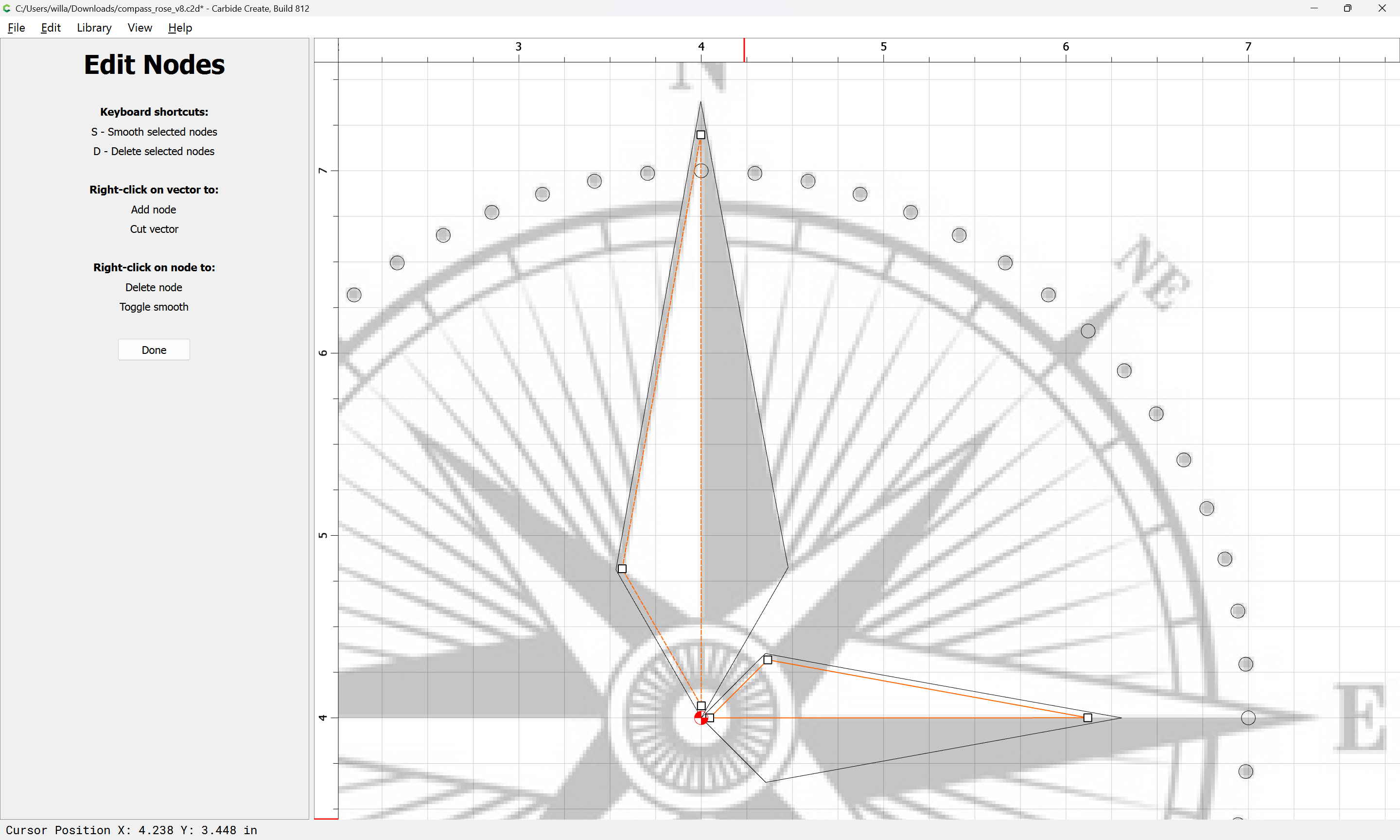
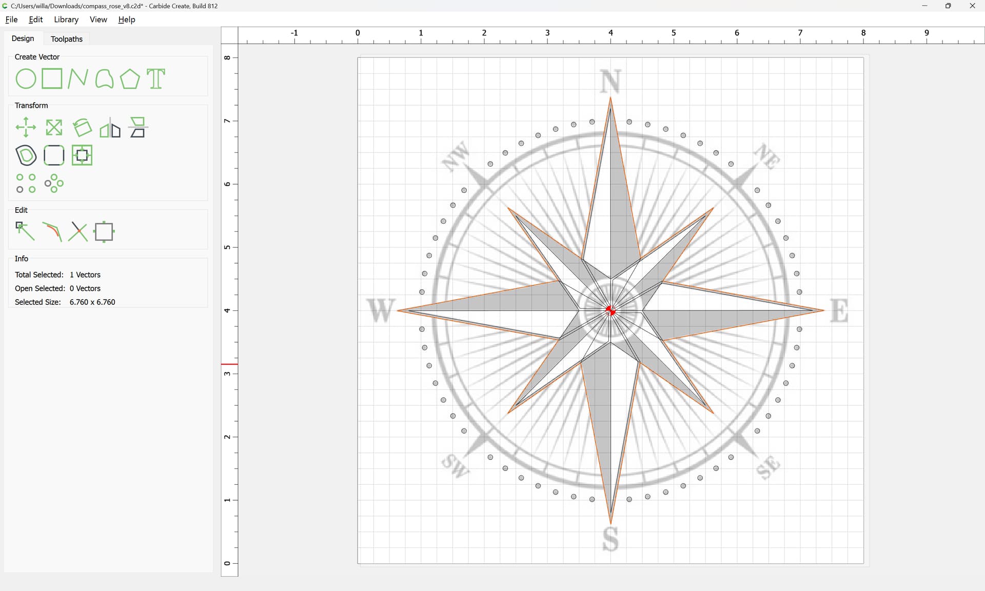
by selecting and deleting some nodes:

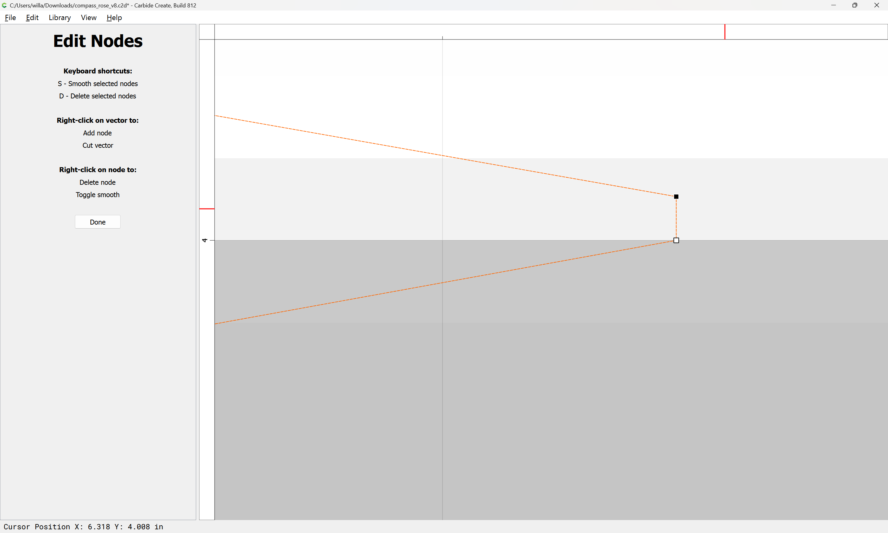
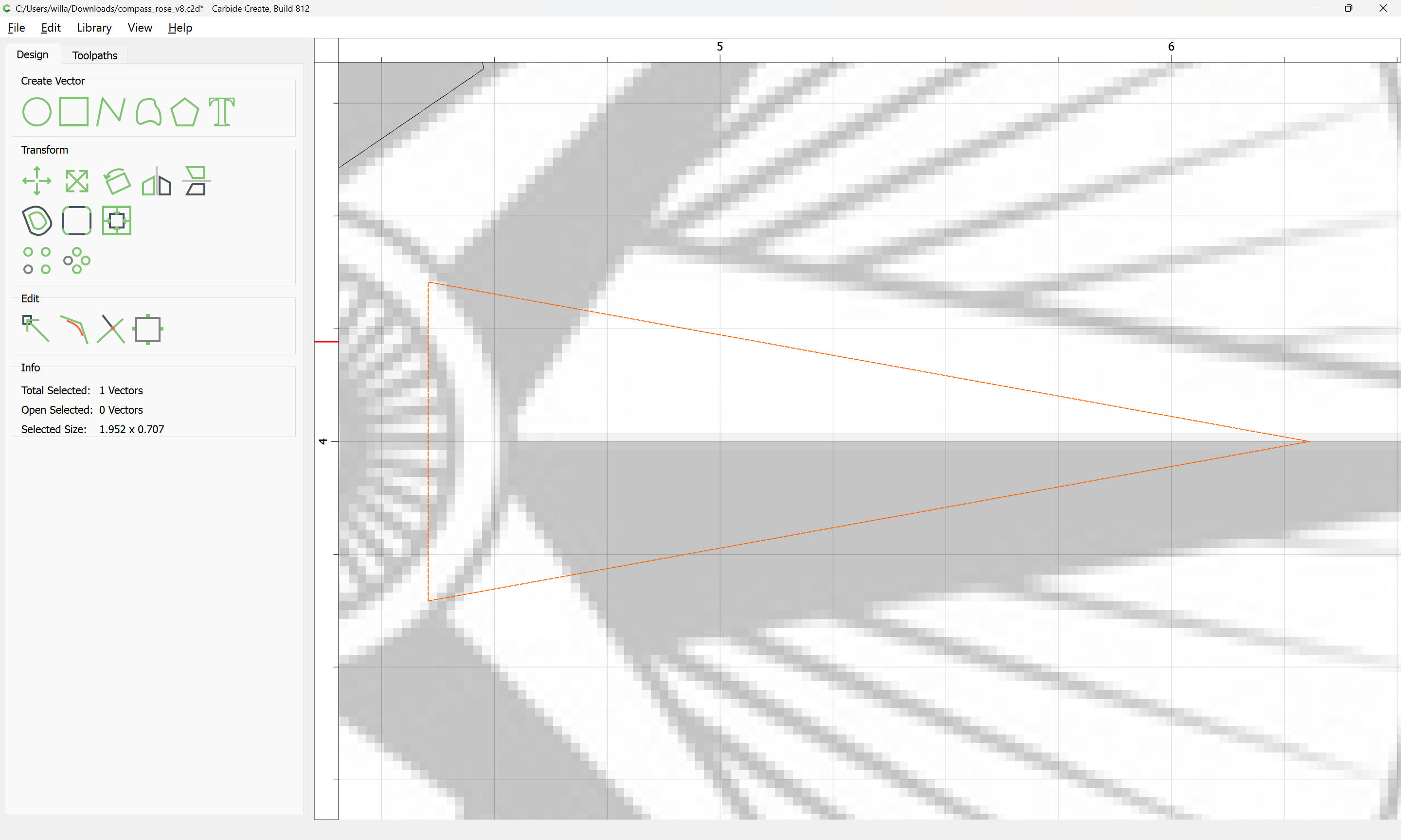
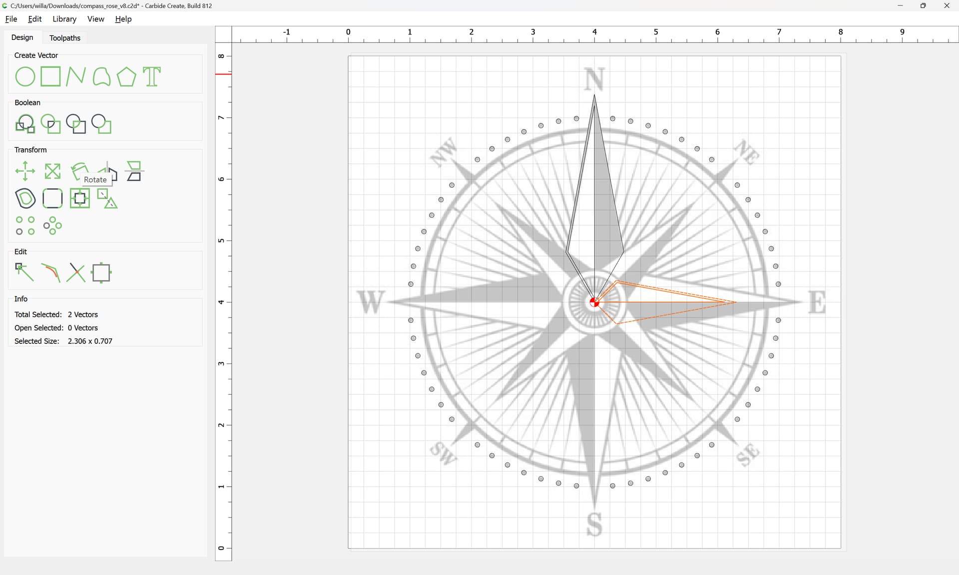
Done
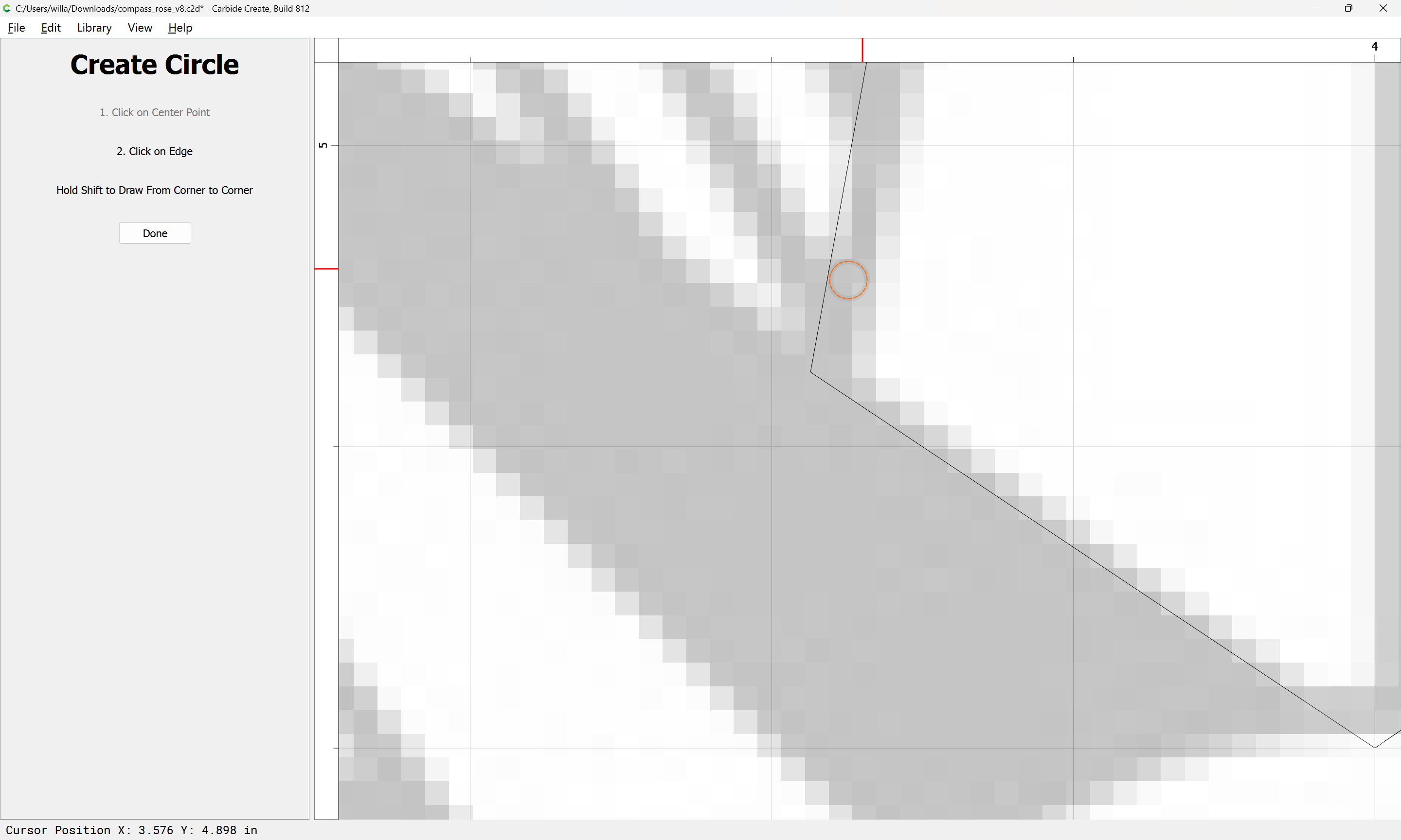
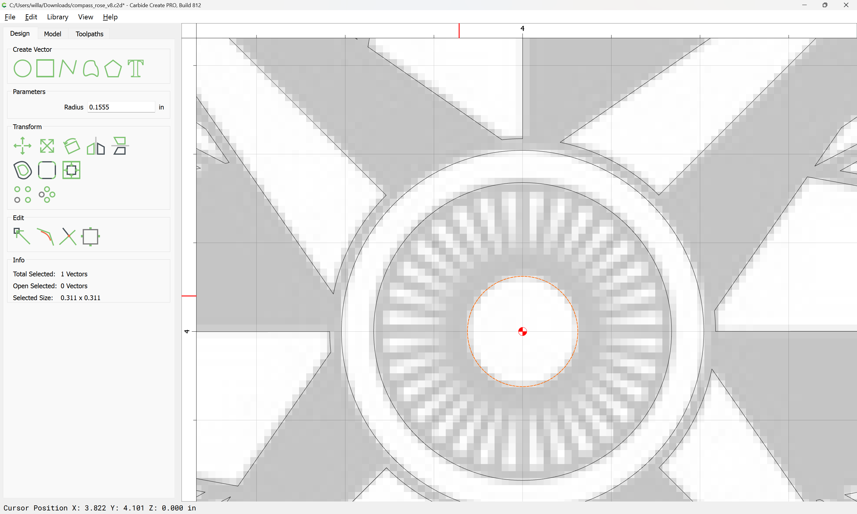
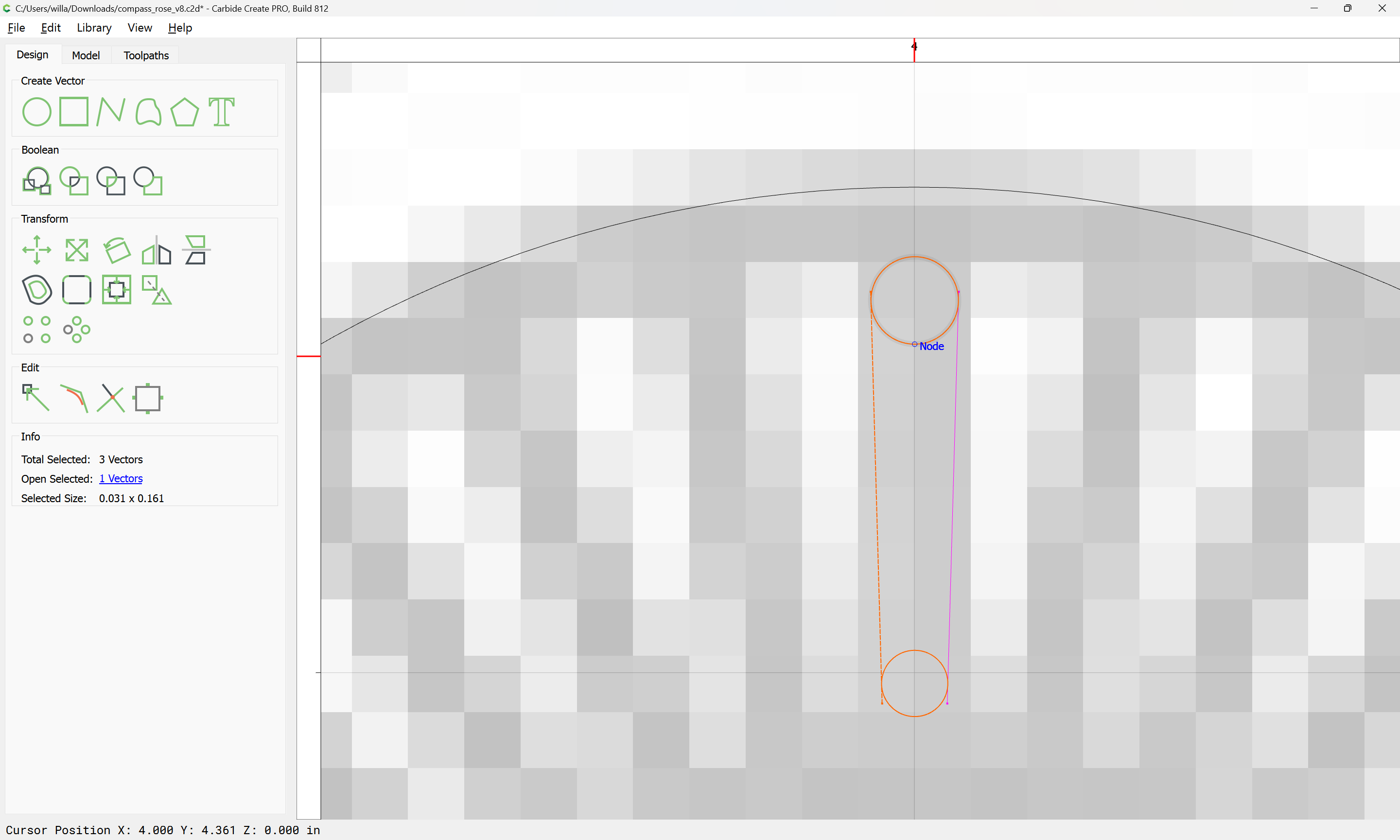
Since an inset will be needed, draw in a circle to get a rough idea of the dimension for that:
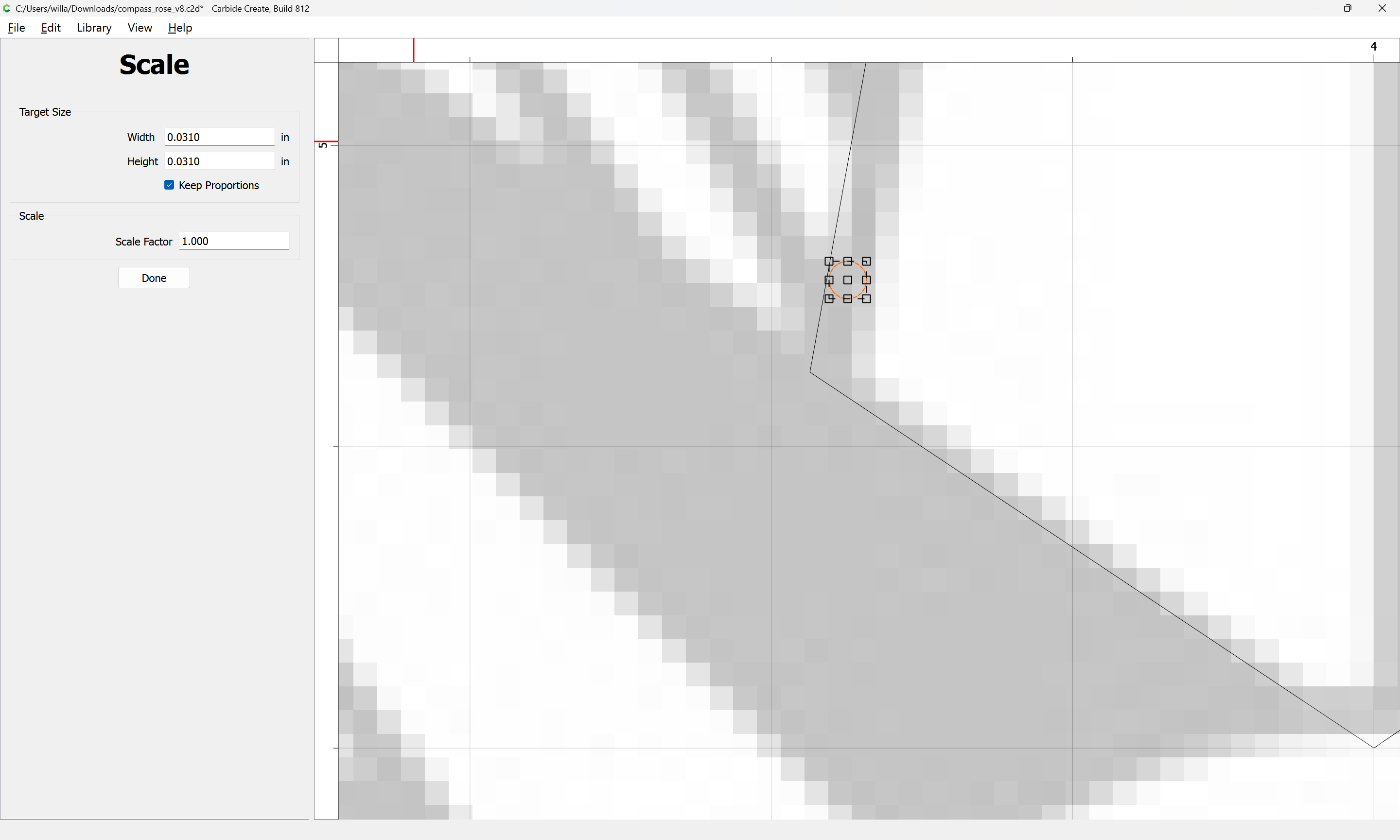
Because of the need to do this, it would be best to overdraw the elements in question:
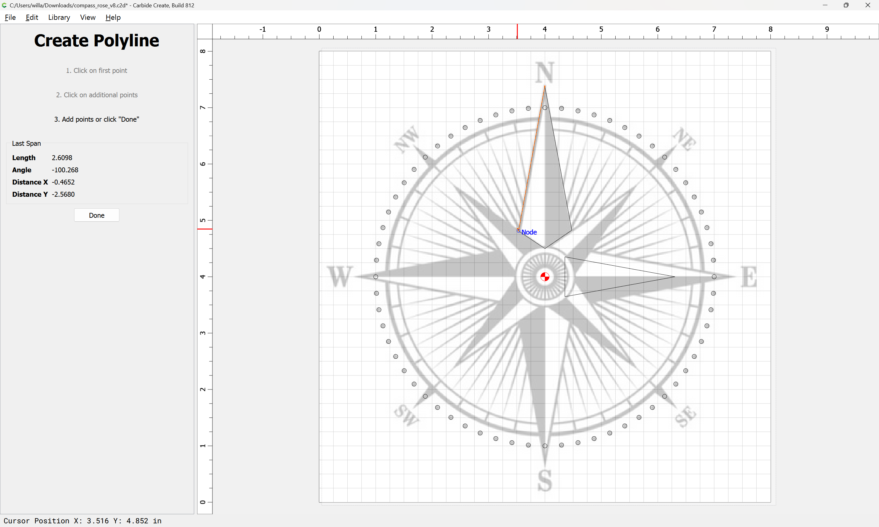
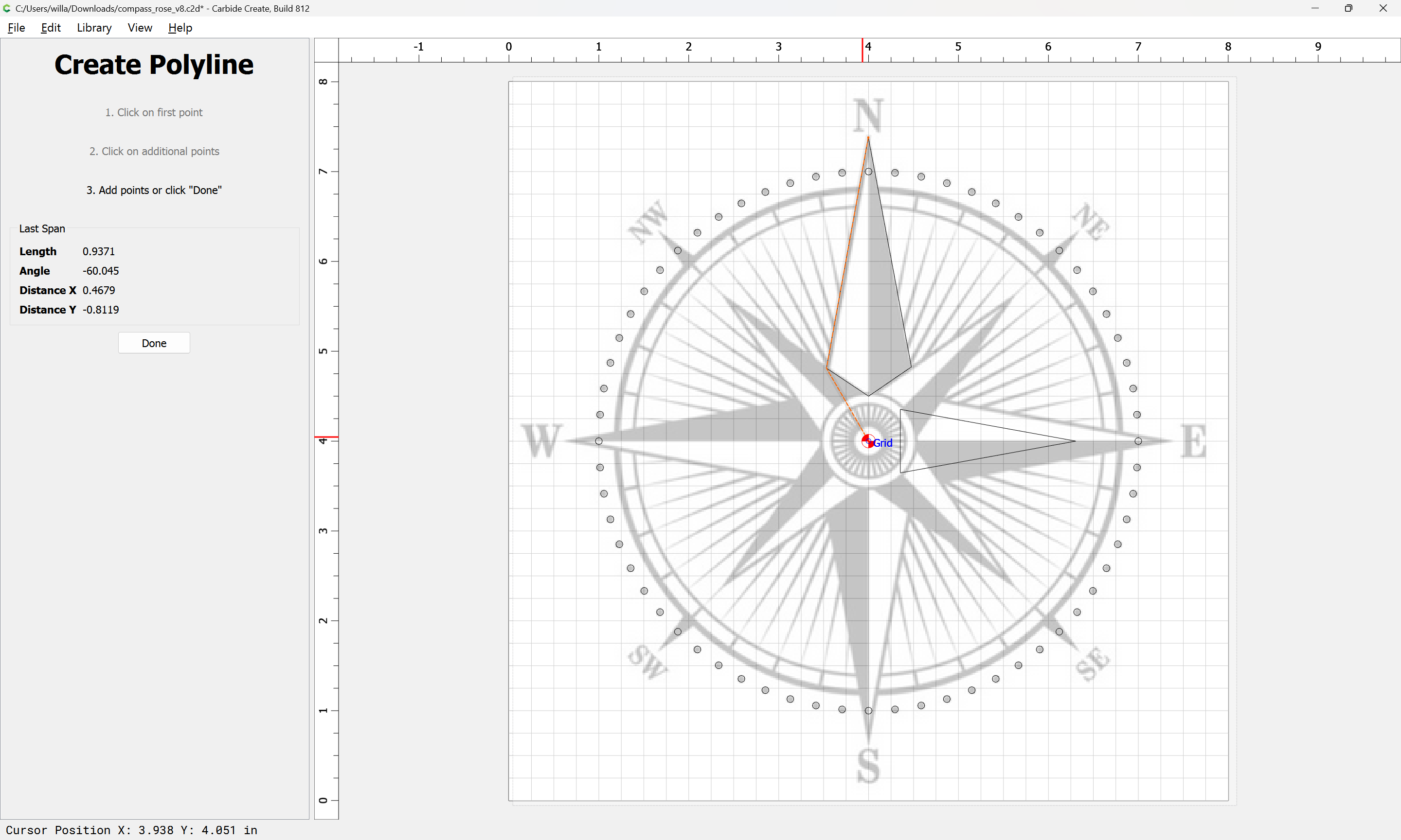
Positioning one node at the center:

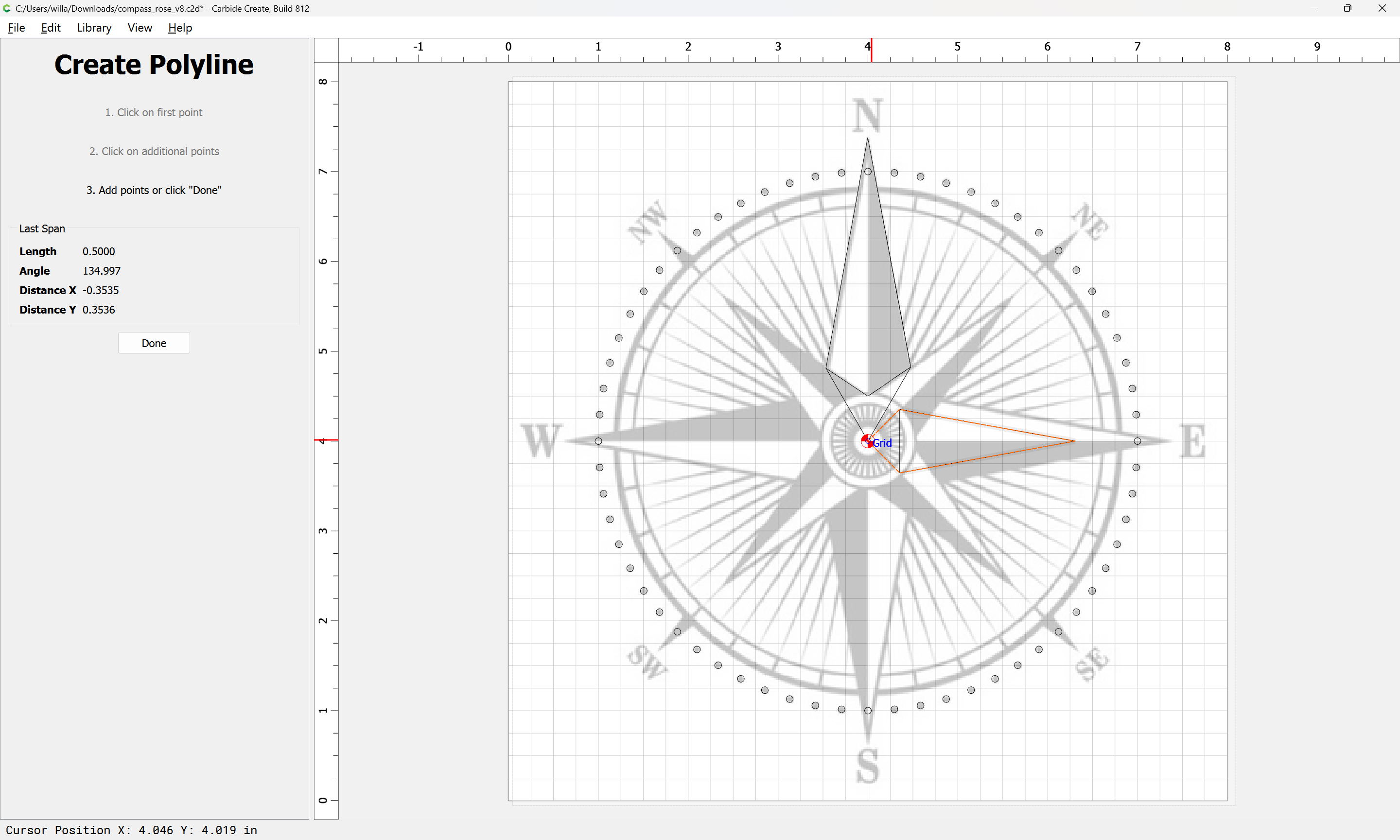
Delete the originals:

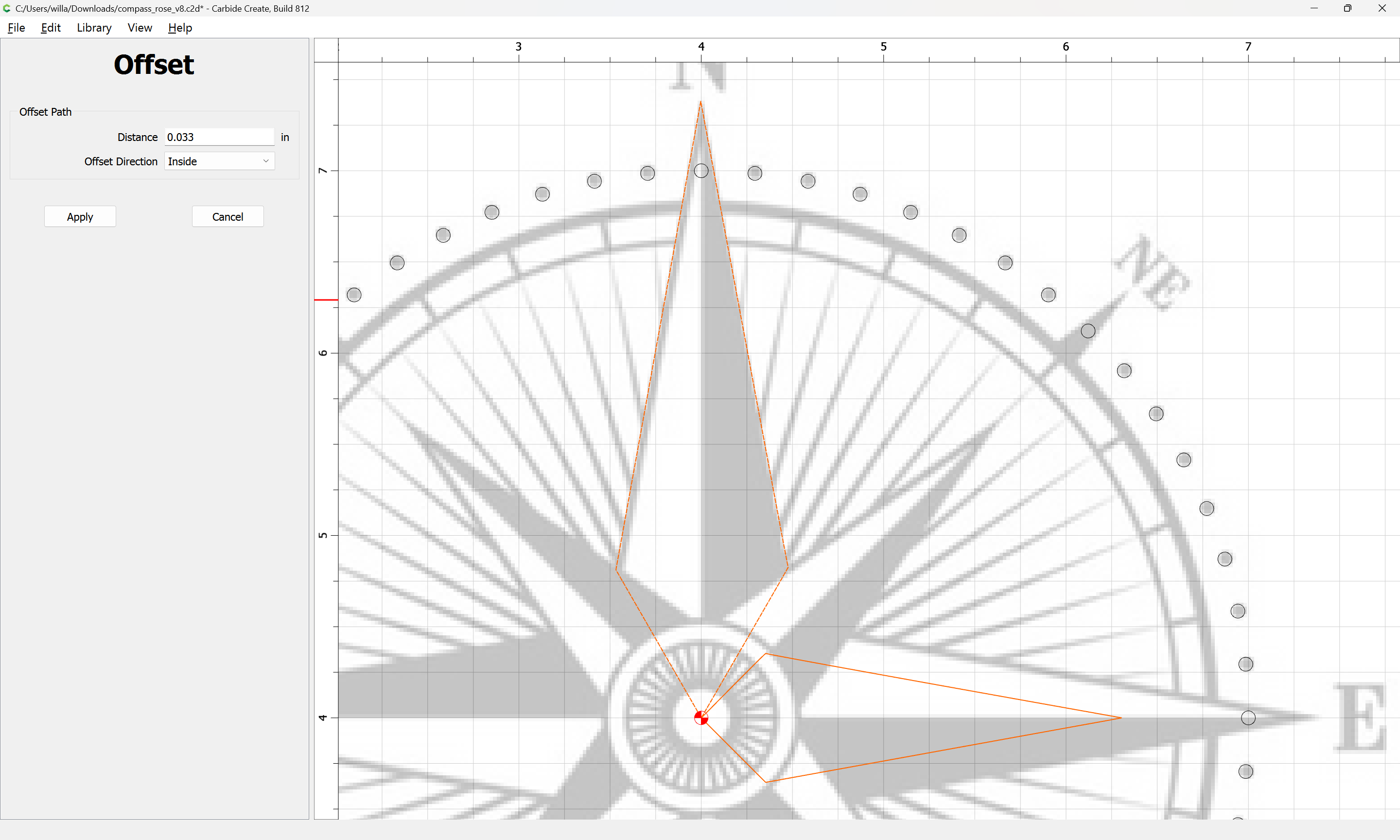
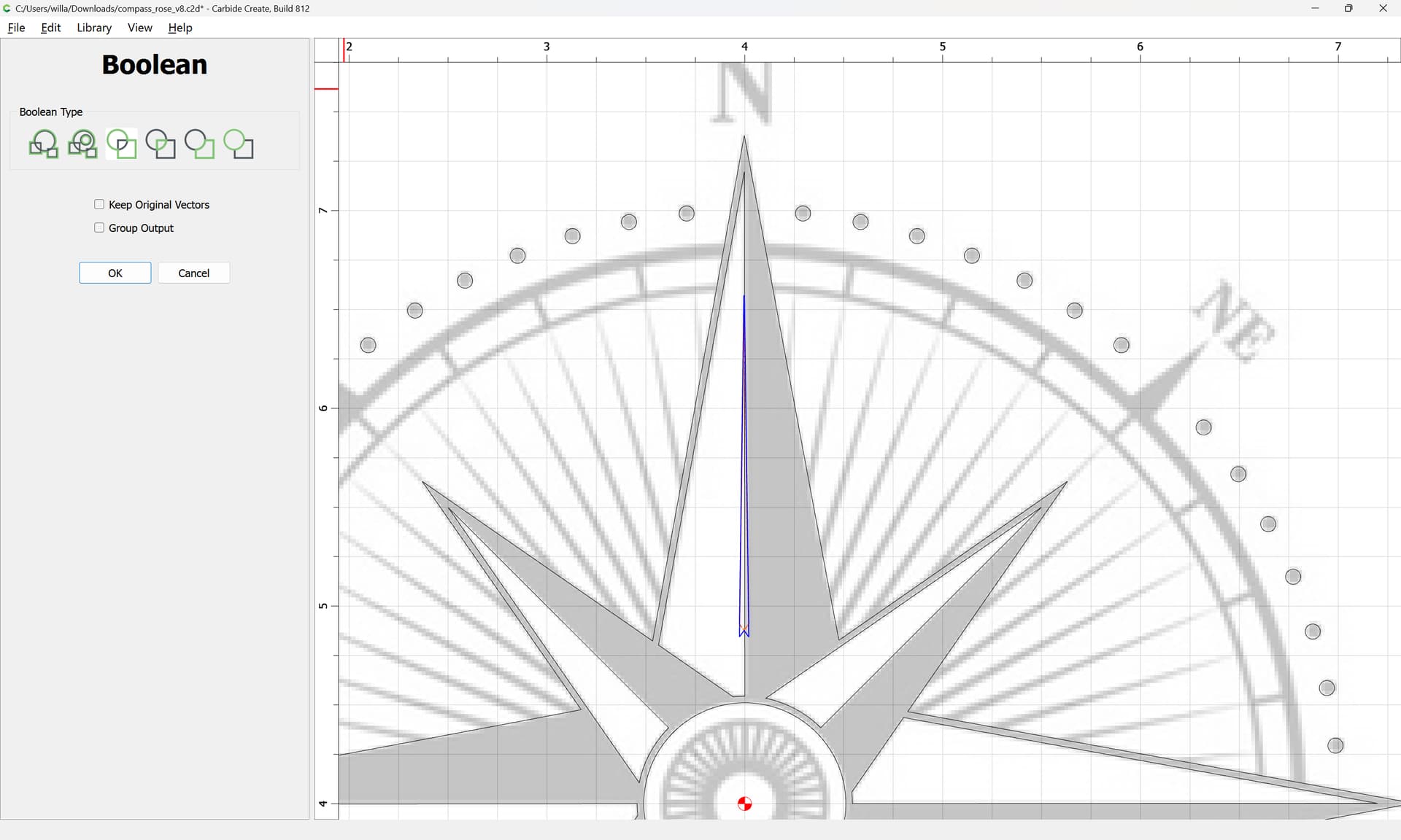
Select the two elements and inset:
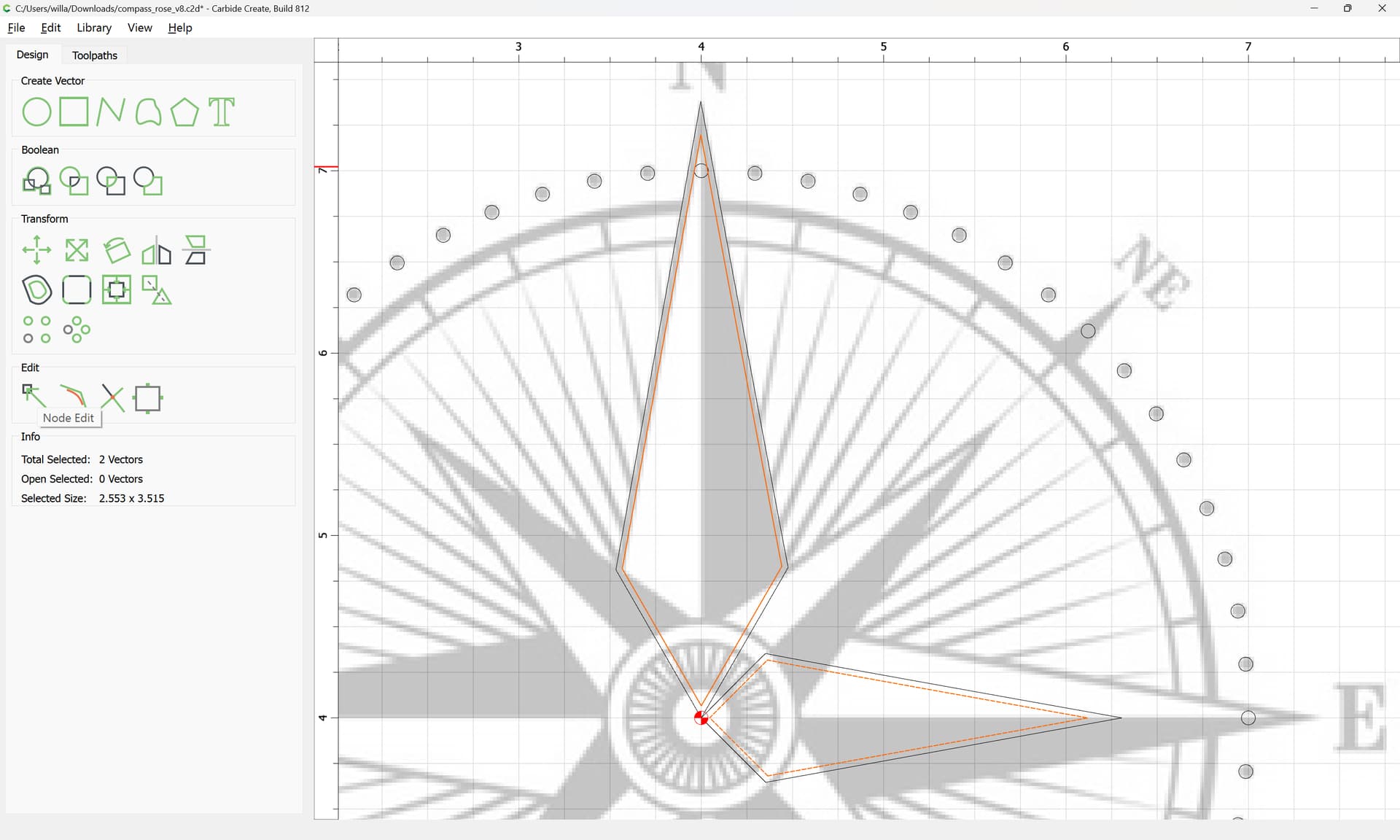
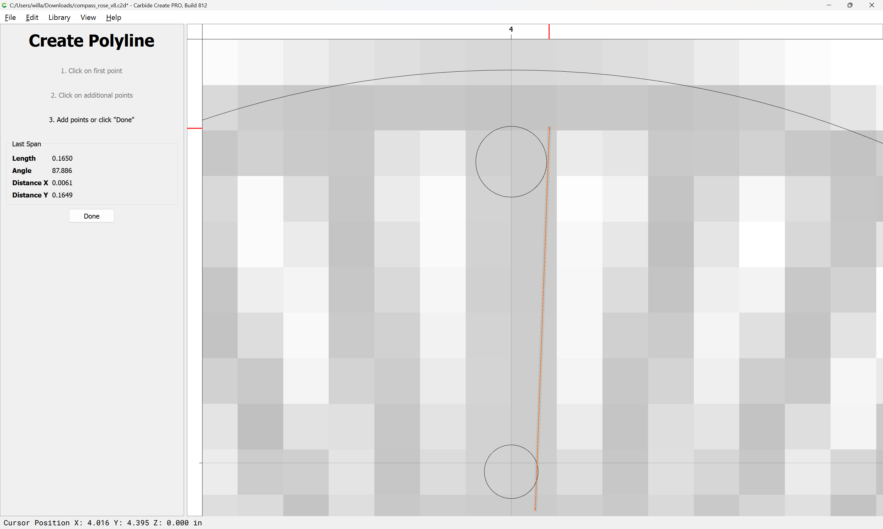
Node edit them to create the white highlight:
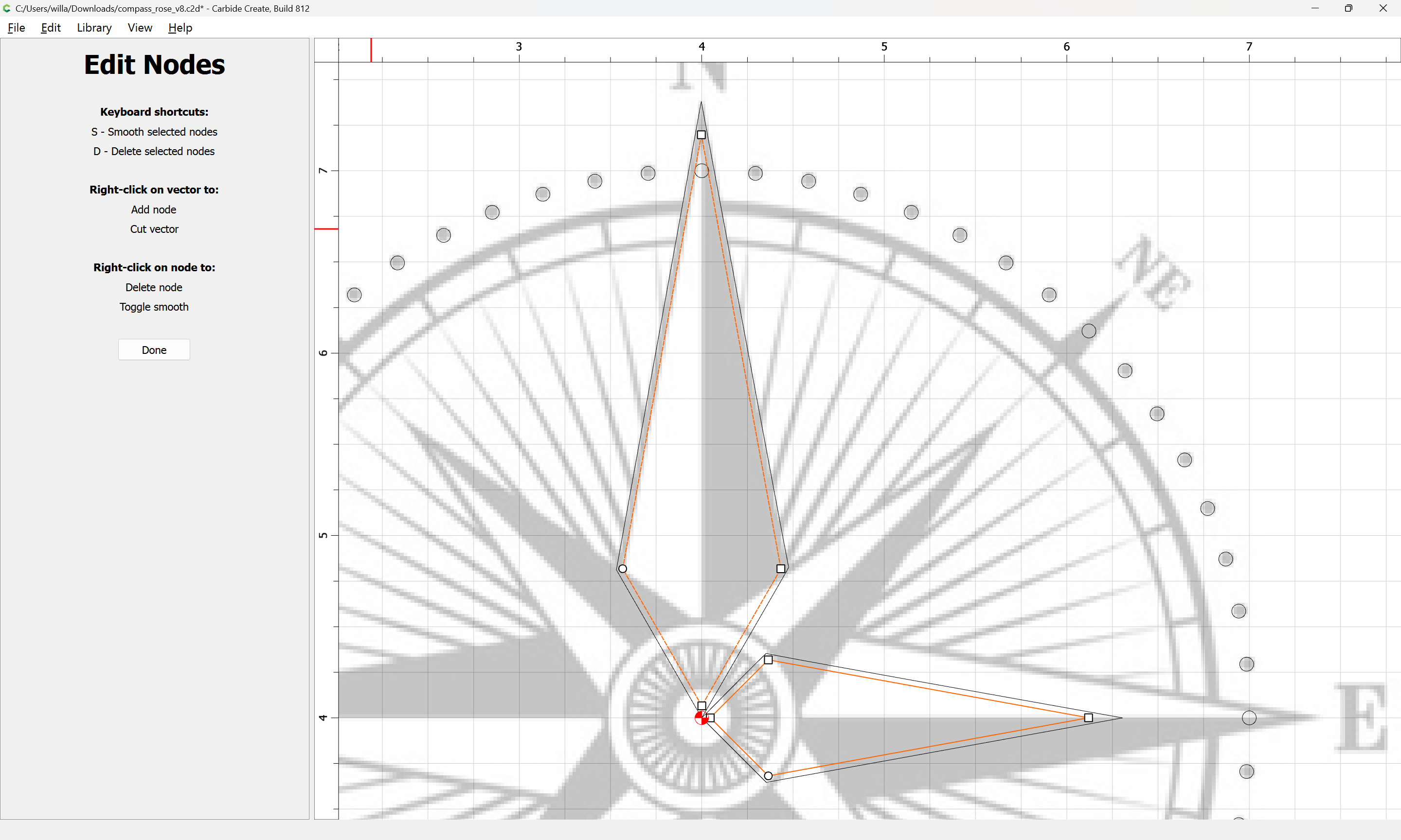
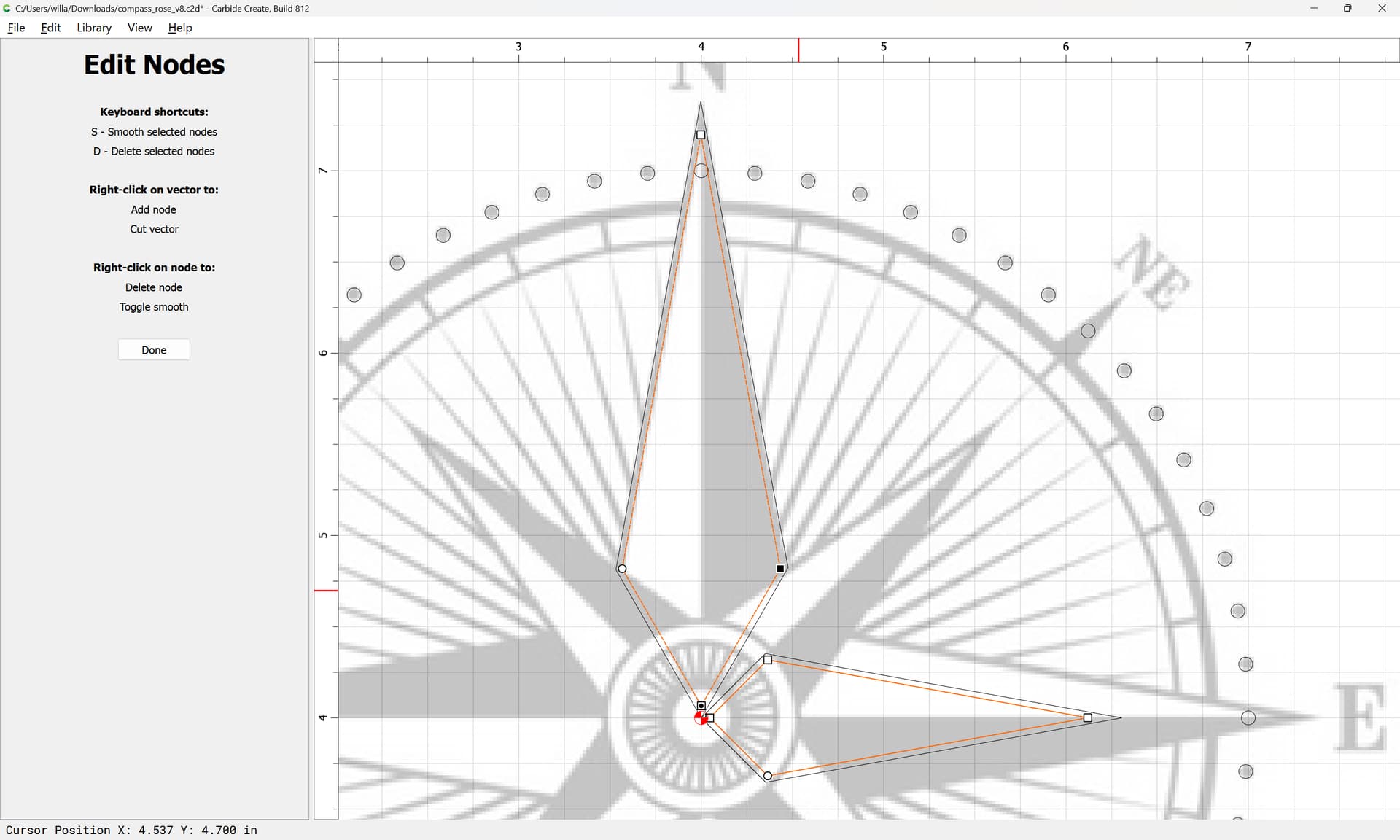
If a Curve is created, just toggle node settings until things straighten out:

Repeat:

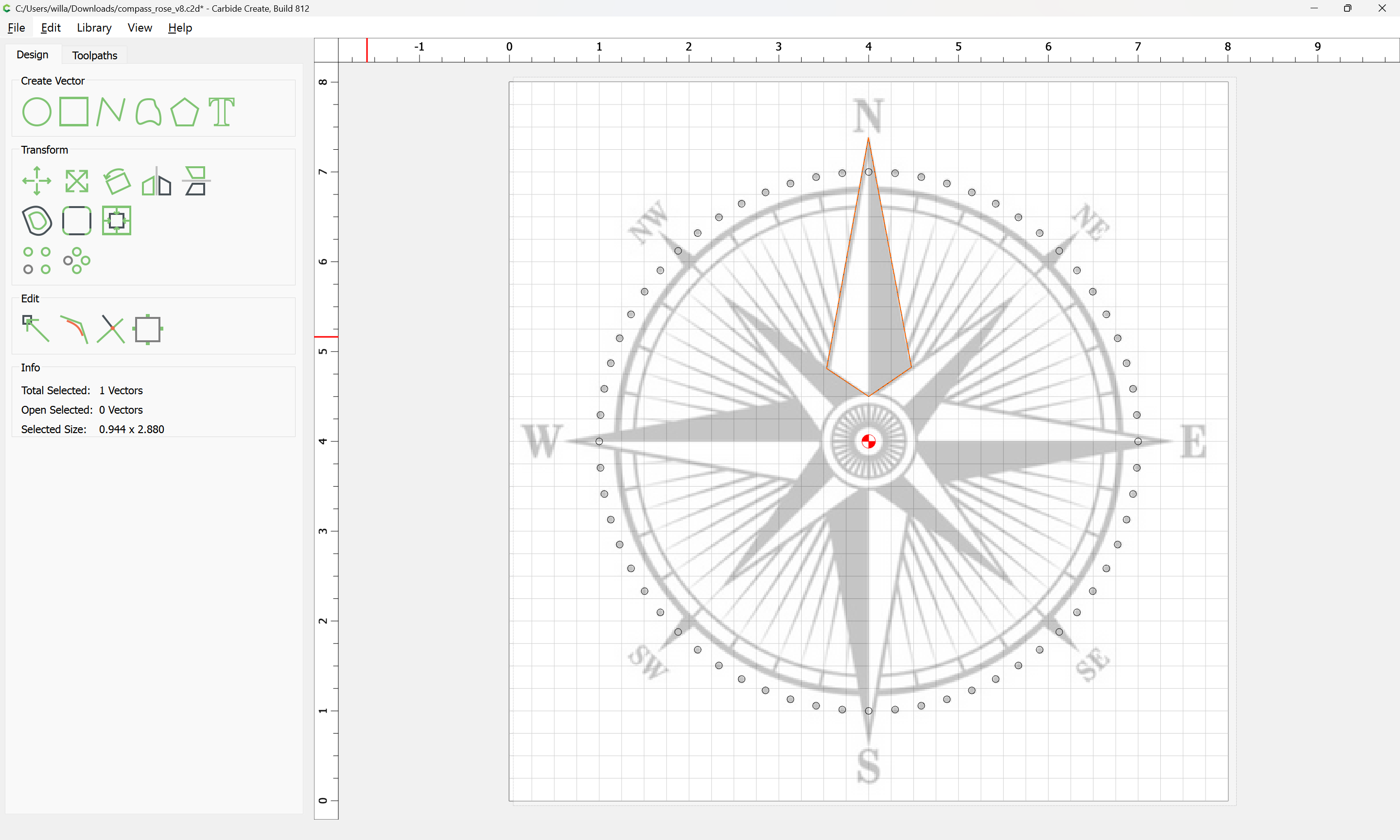
Select the element which was rotated:
and reverse the rotation:
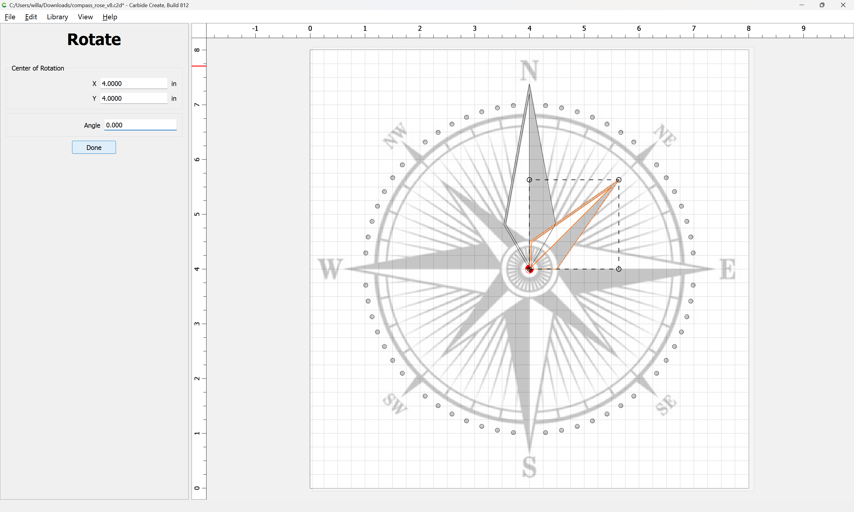
Done
1 Like
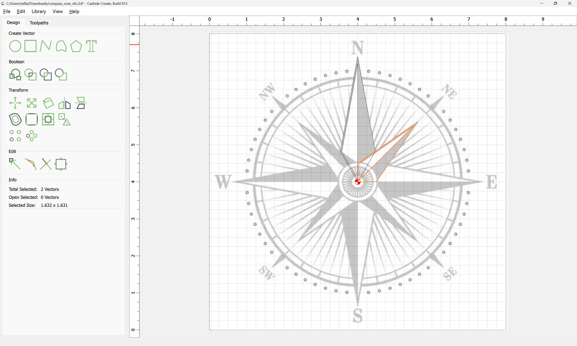
Since these elements now have a node at the center, and since there aren’t many of them and since some mirroring will be needed which will result in the correct position, the most expedient thing to do is to copy-paste and mirror as necessary to position things:
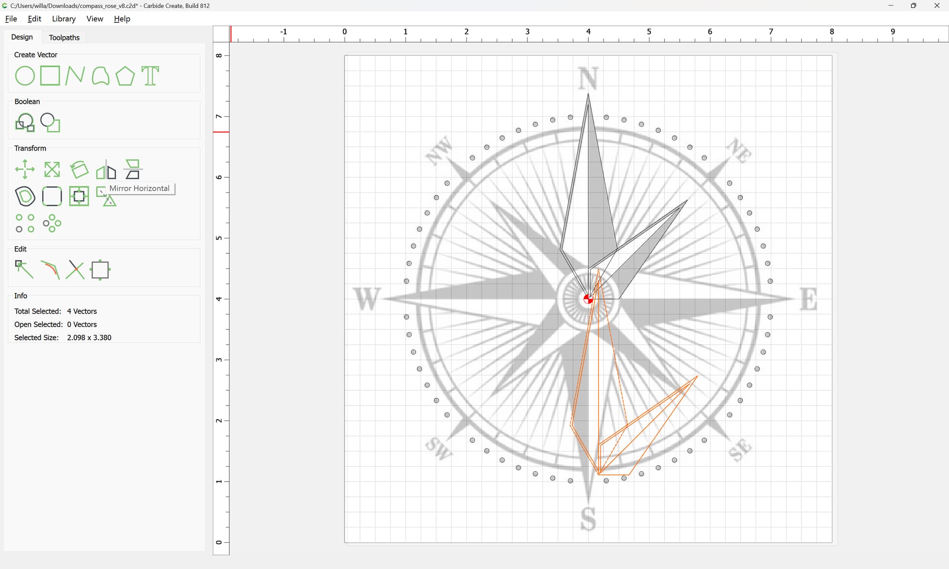
That said, rotation works as well:
Done
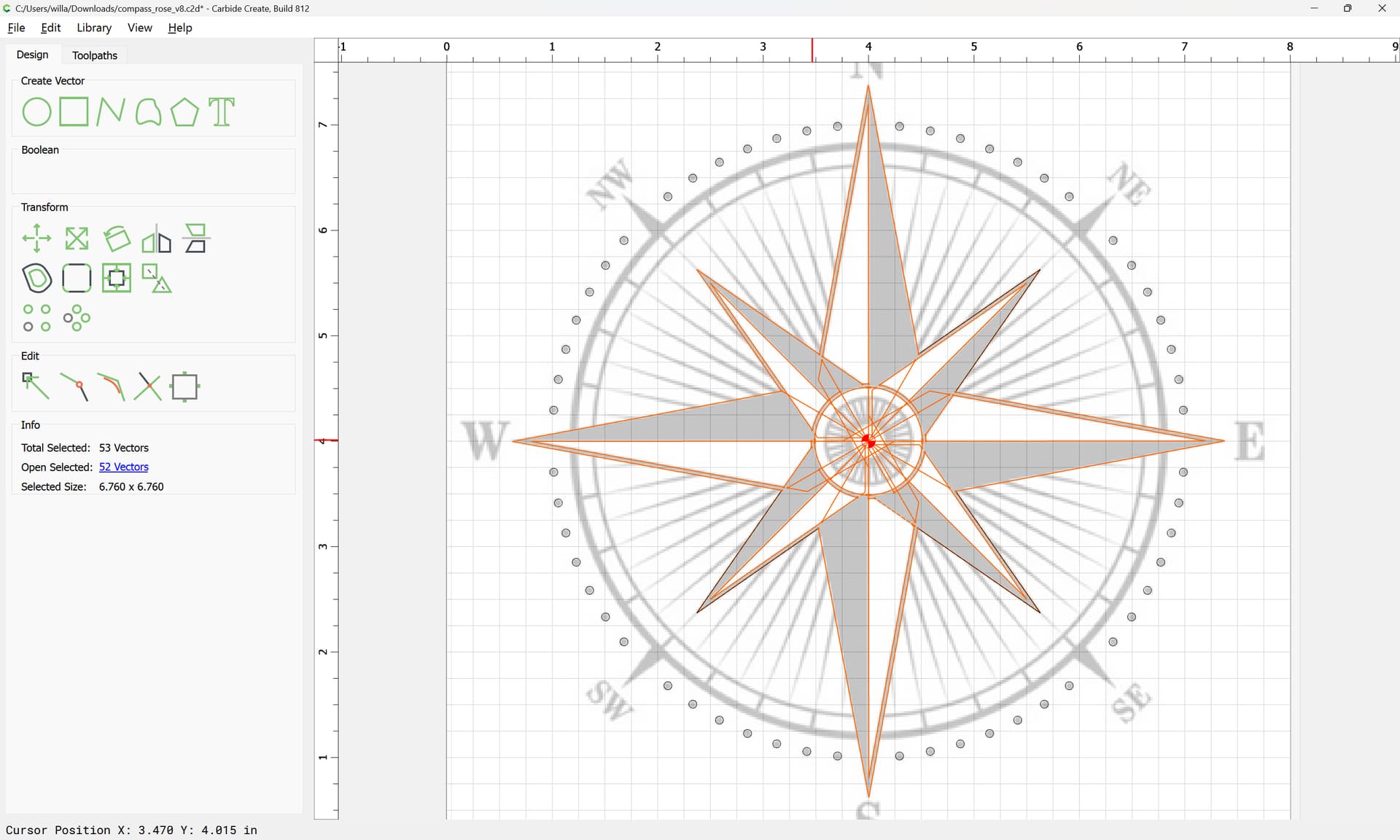
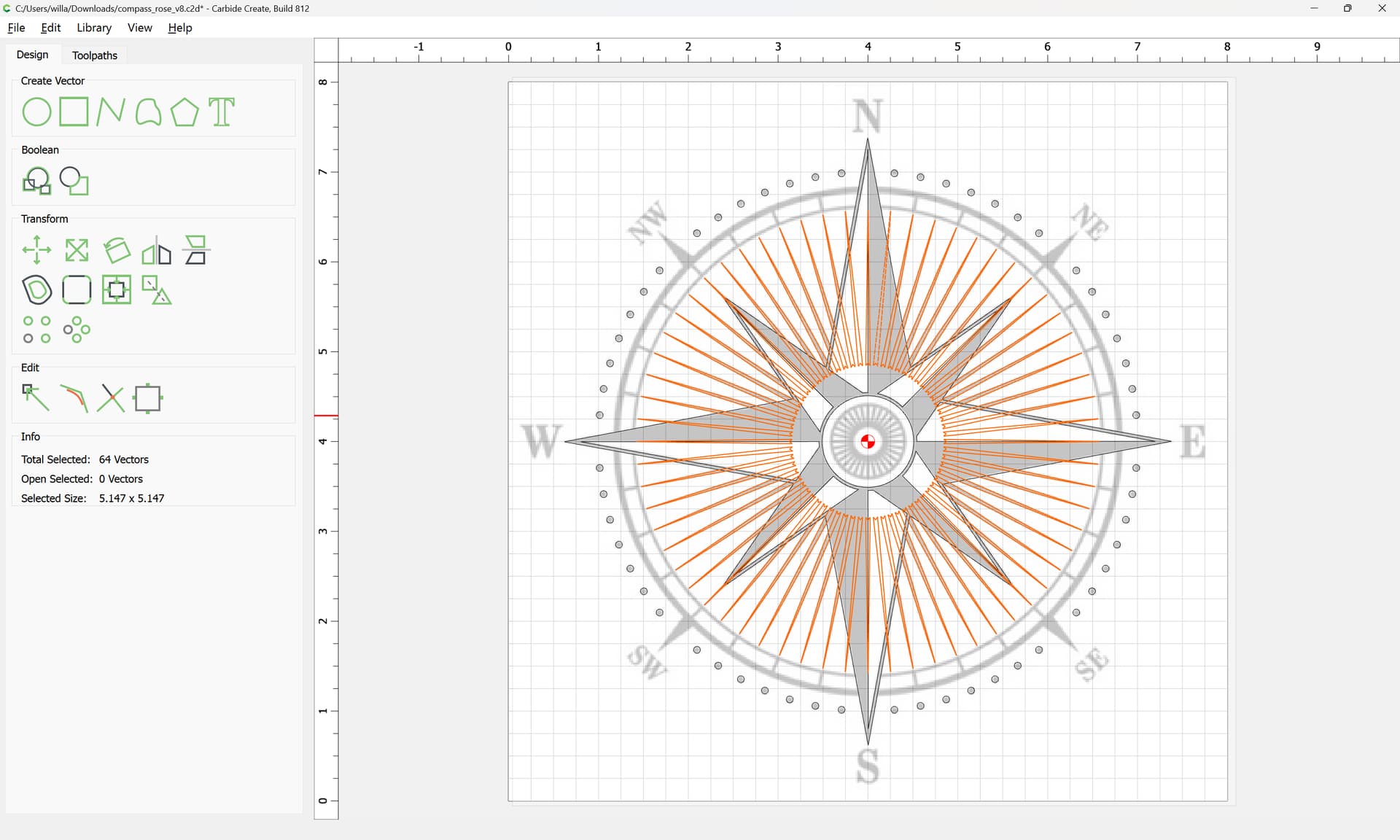
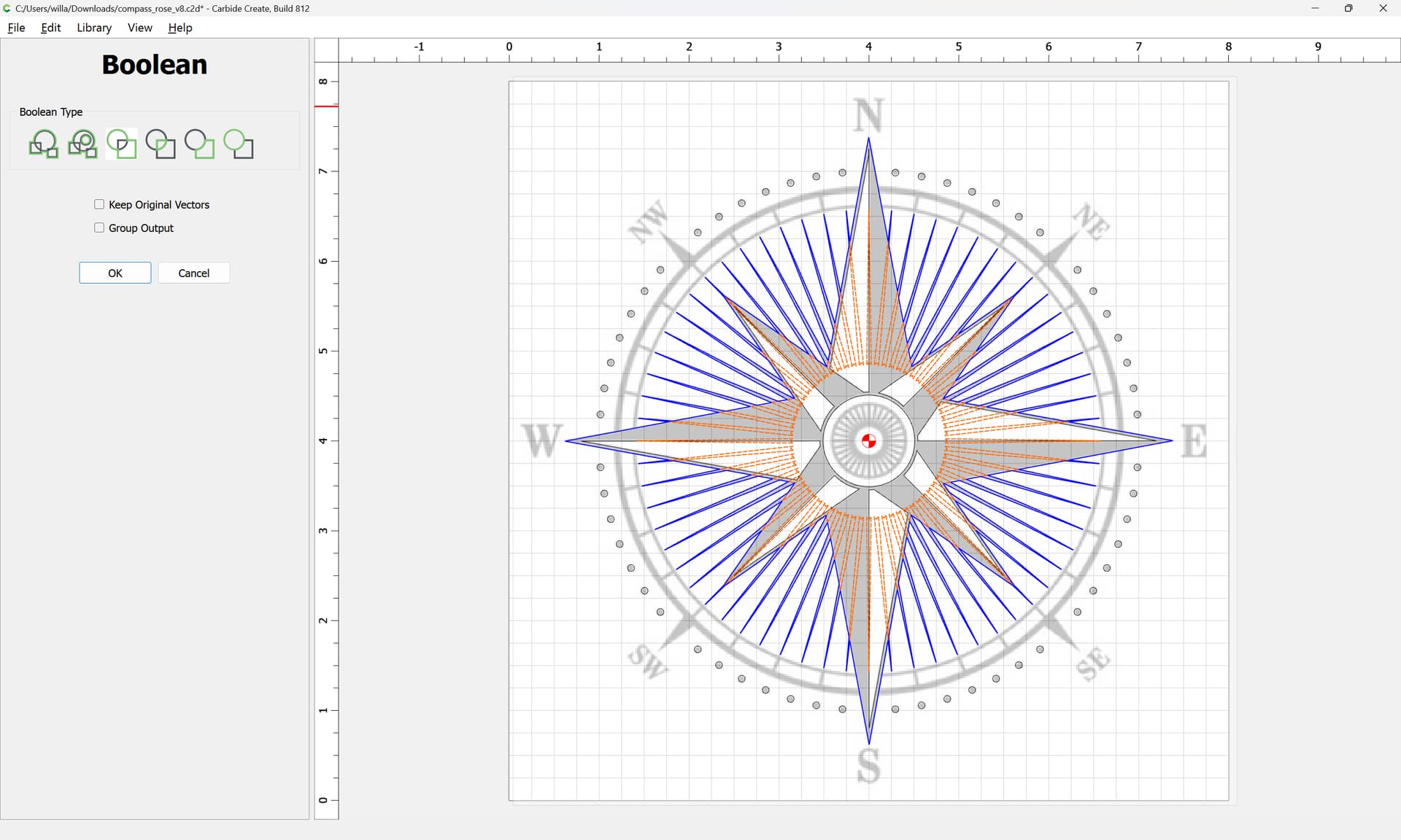
To finish up, select the perimeter geometries:
duplicating them, then
and Boolean Union:
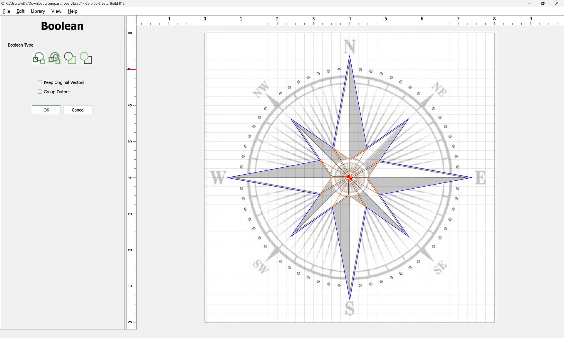
OK
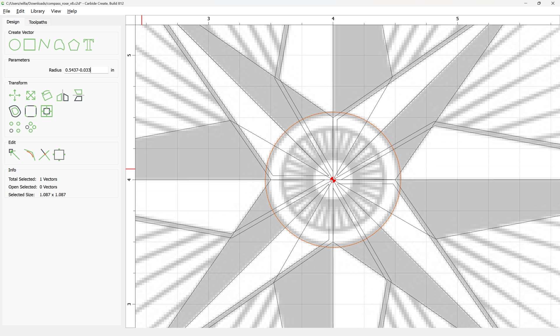
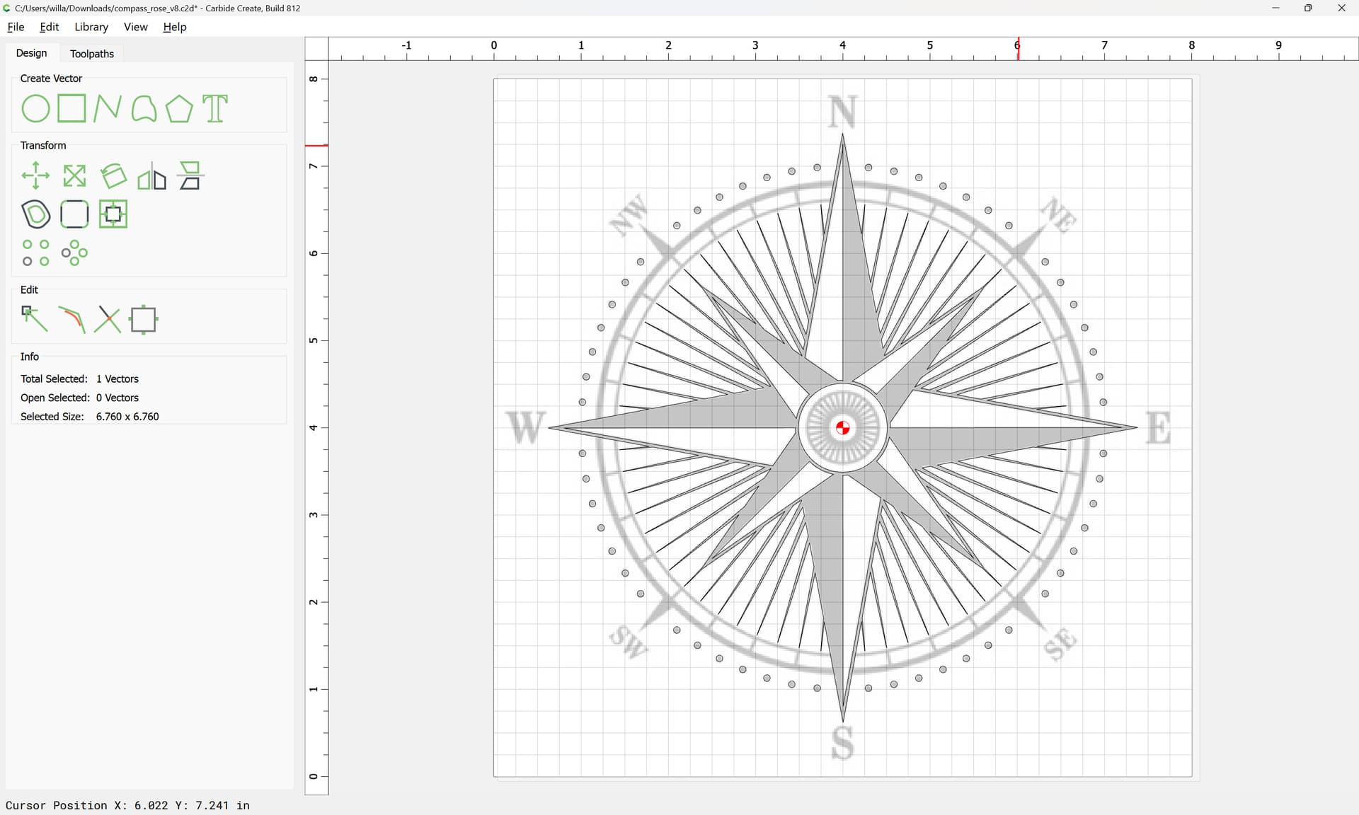
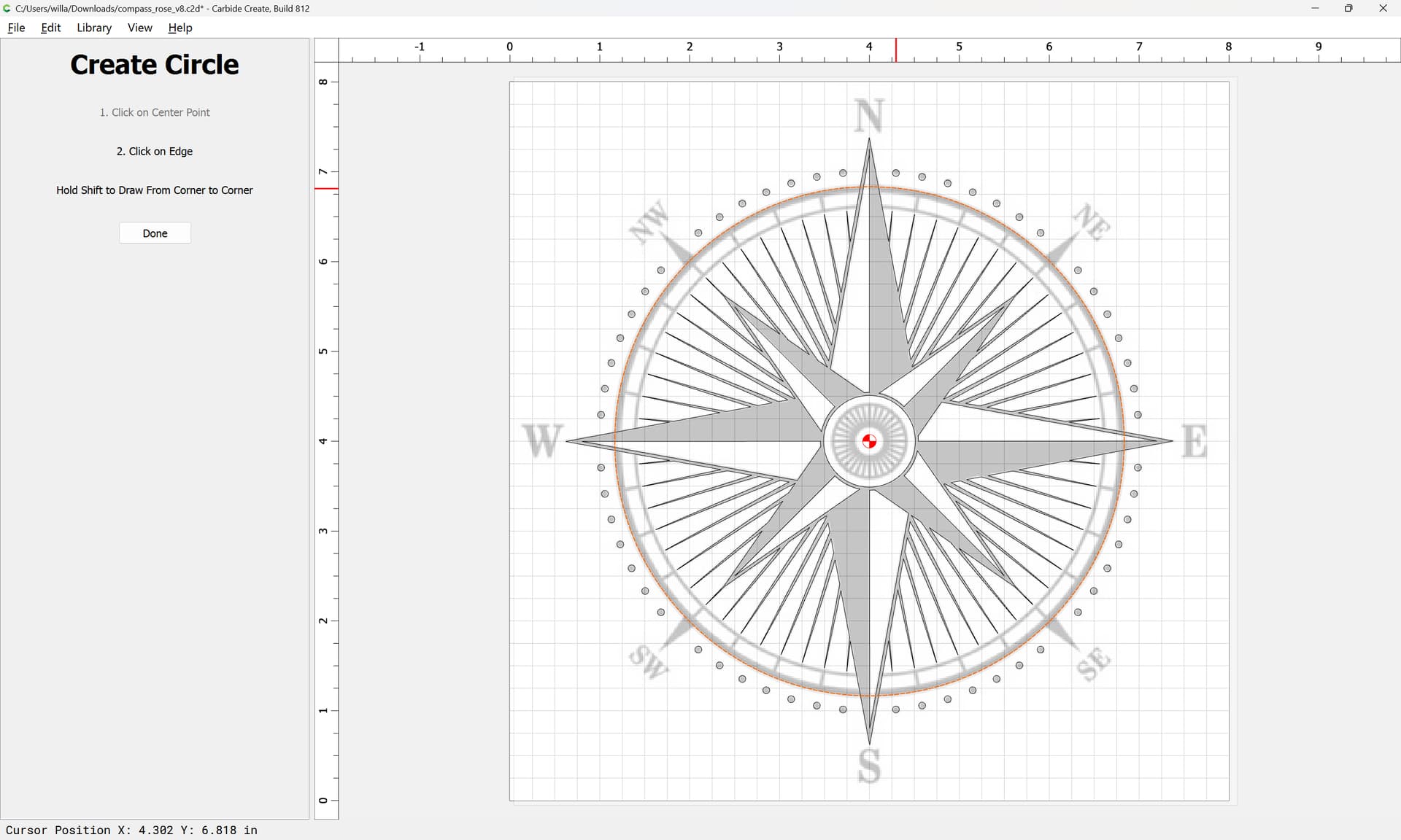
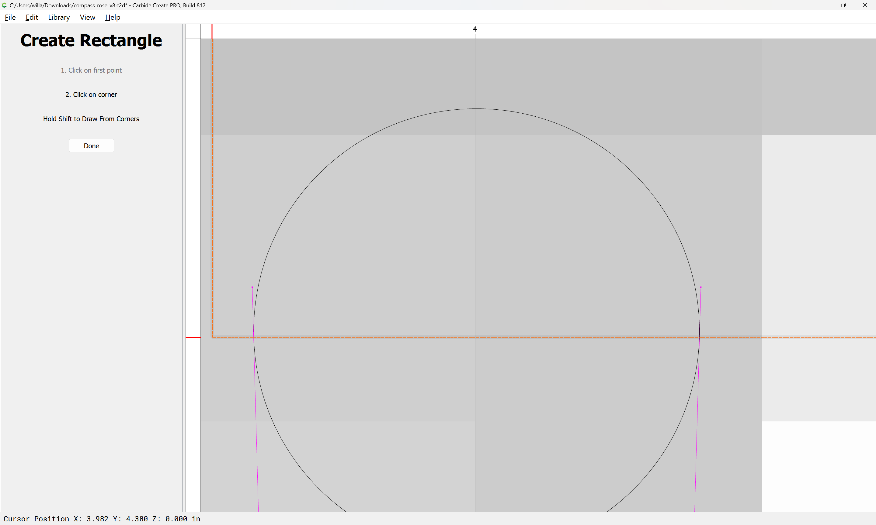
Draw in a circle:
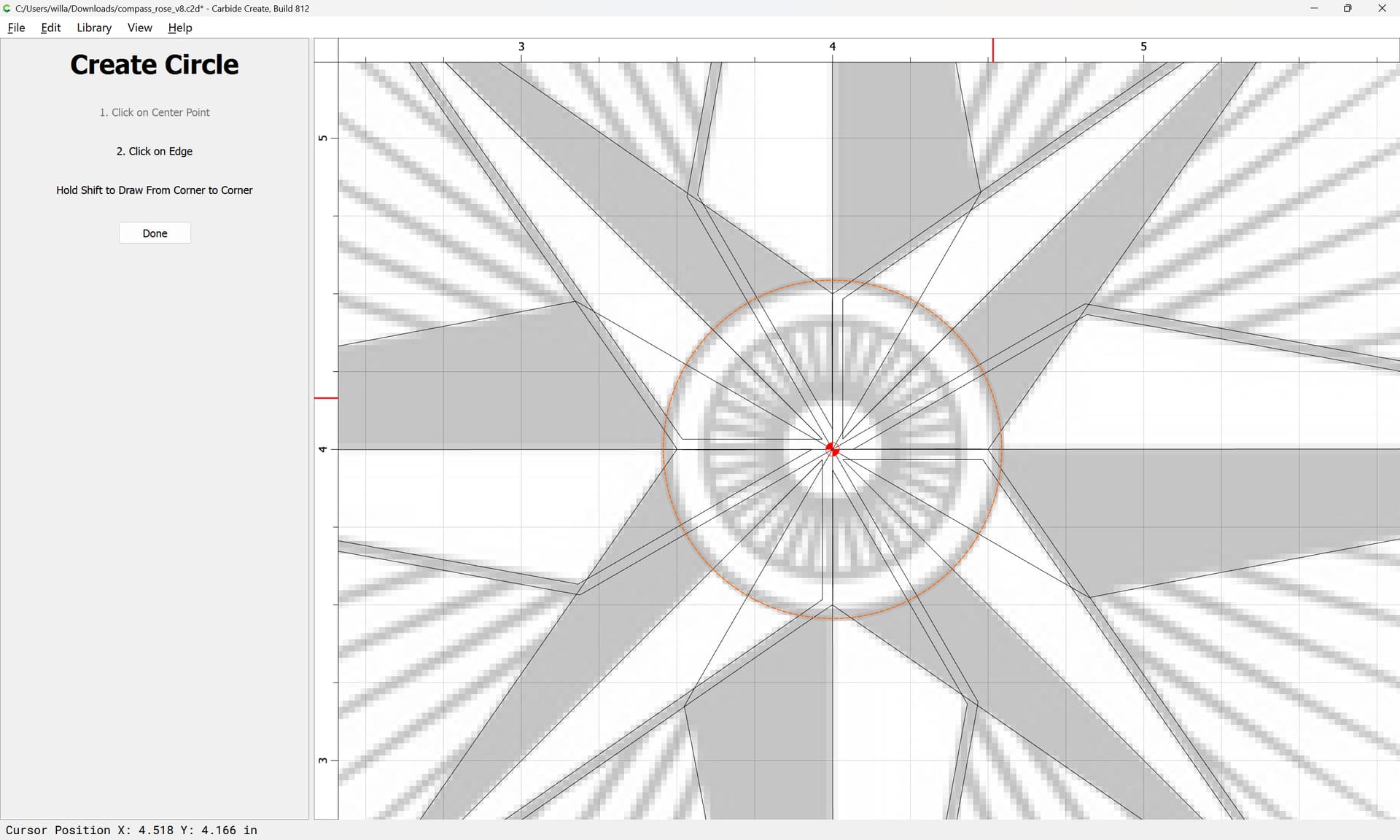
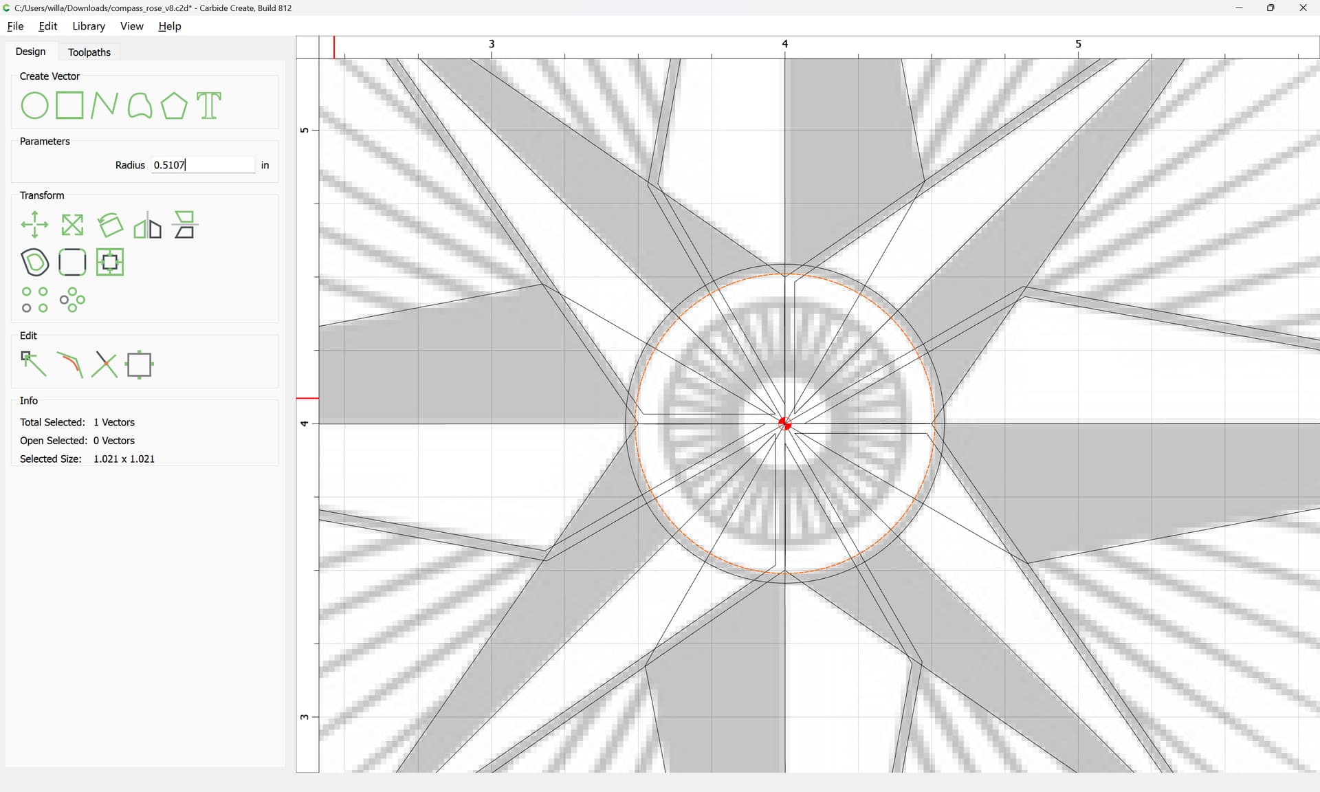
Duplicate it in position and reduce the radius of the duplicate:
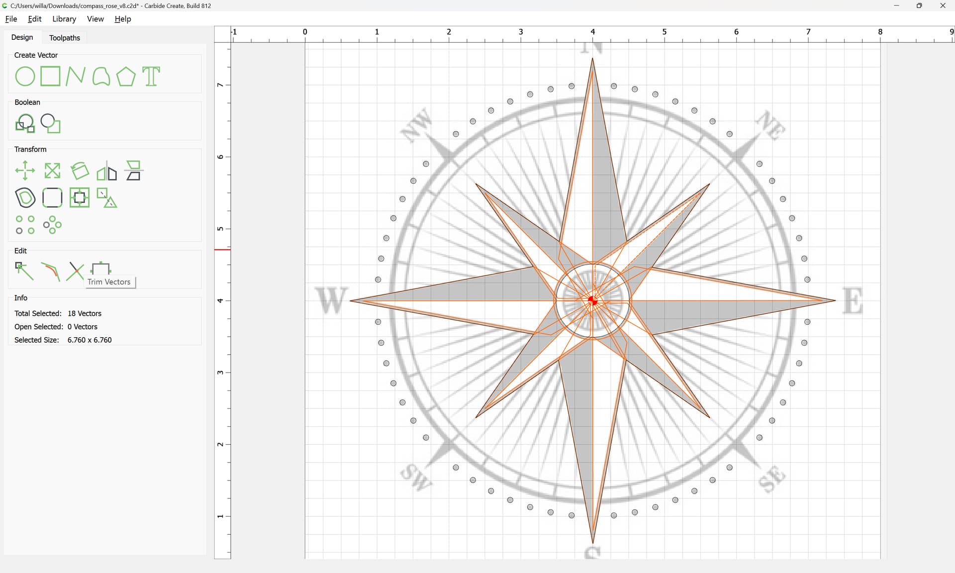
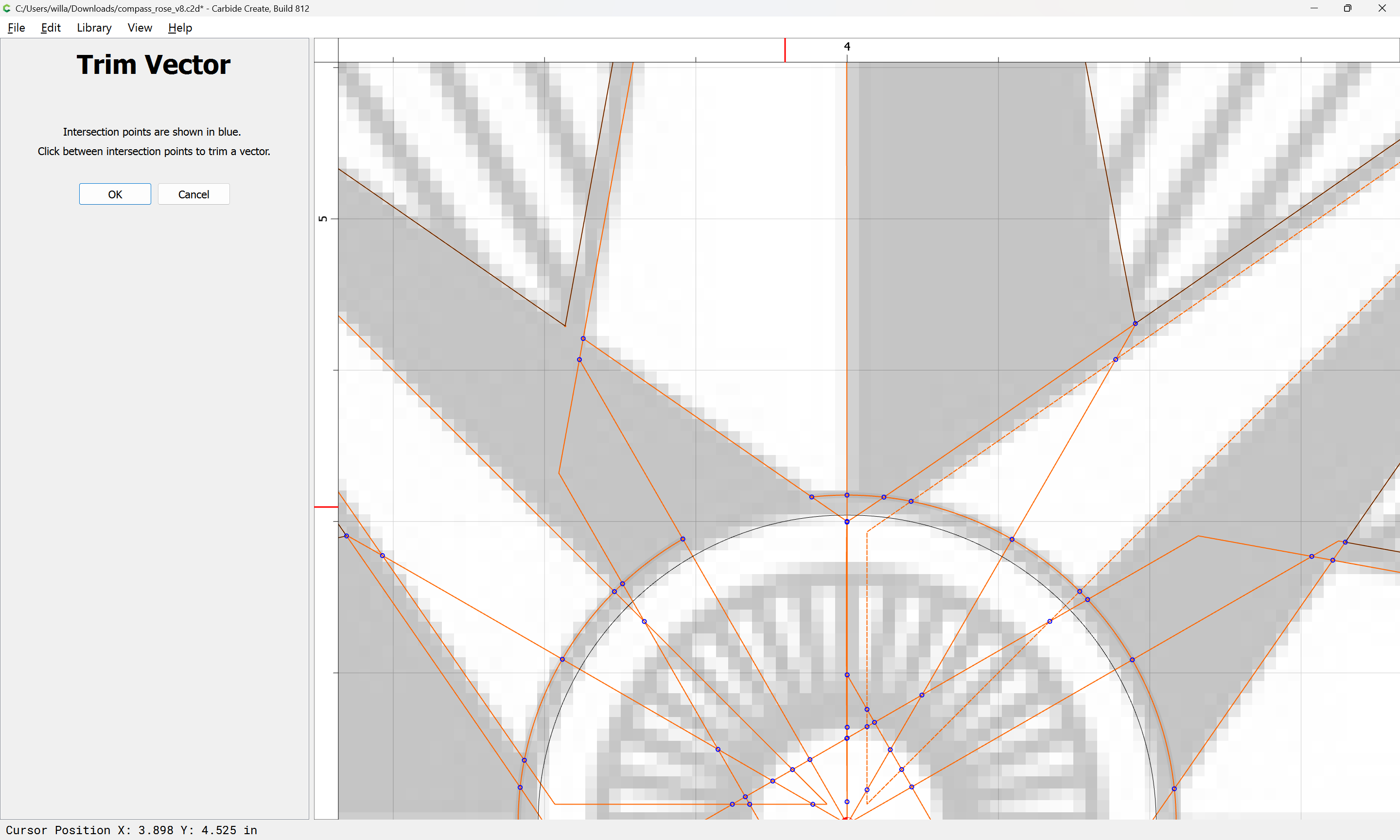
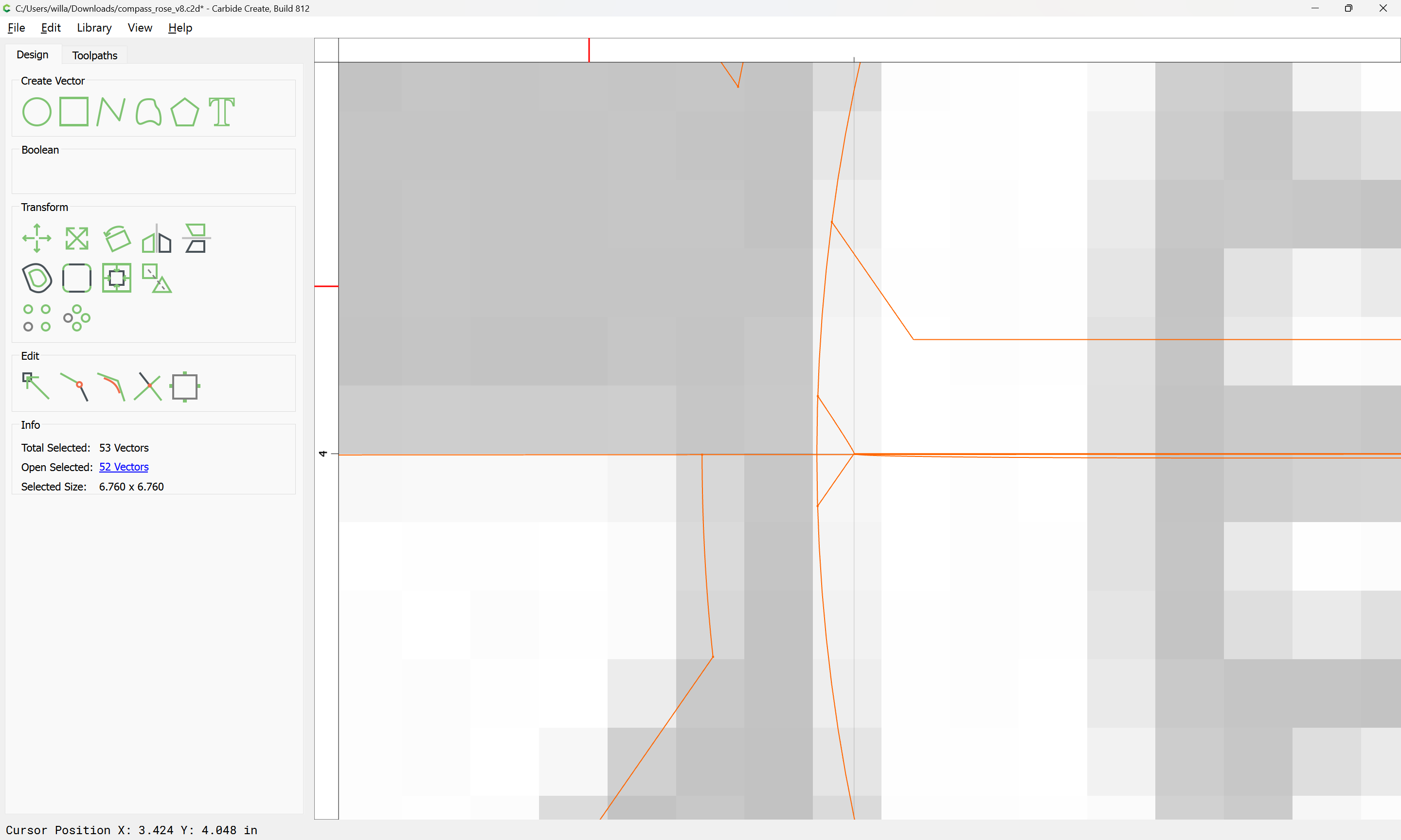
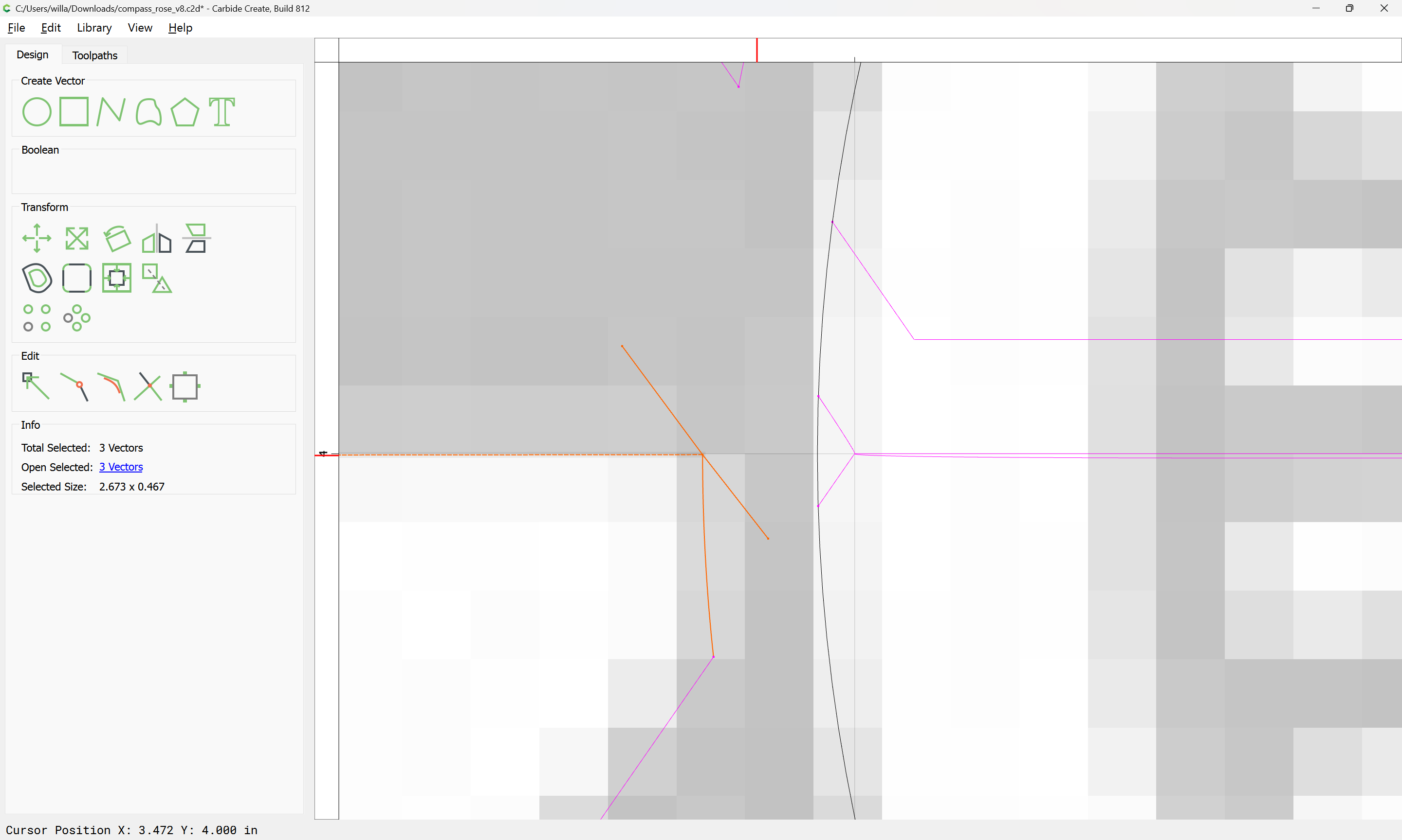
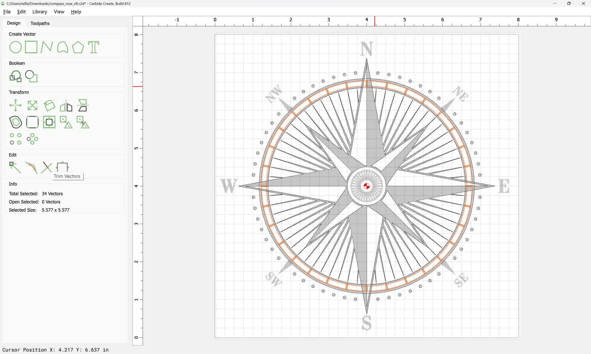
Select all of the interior geometries:
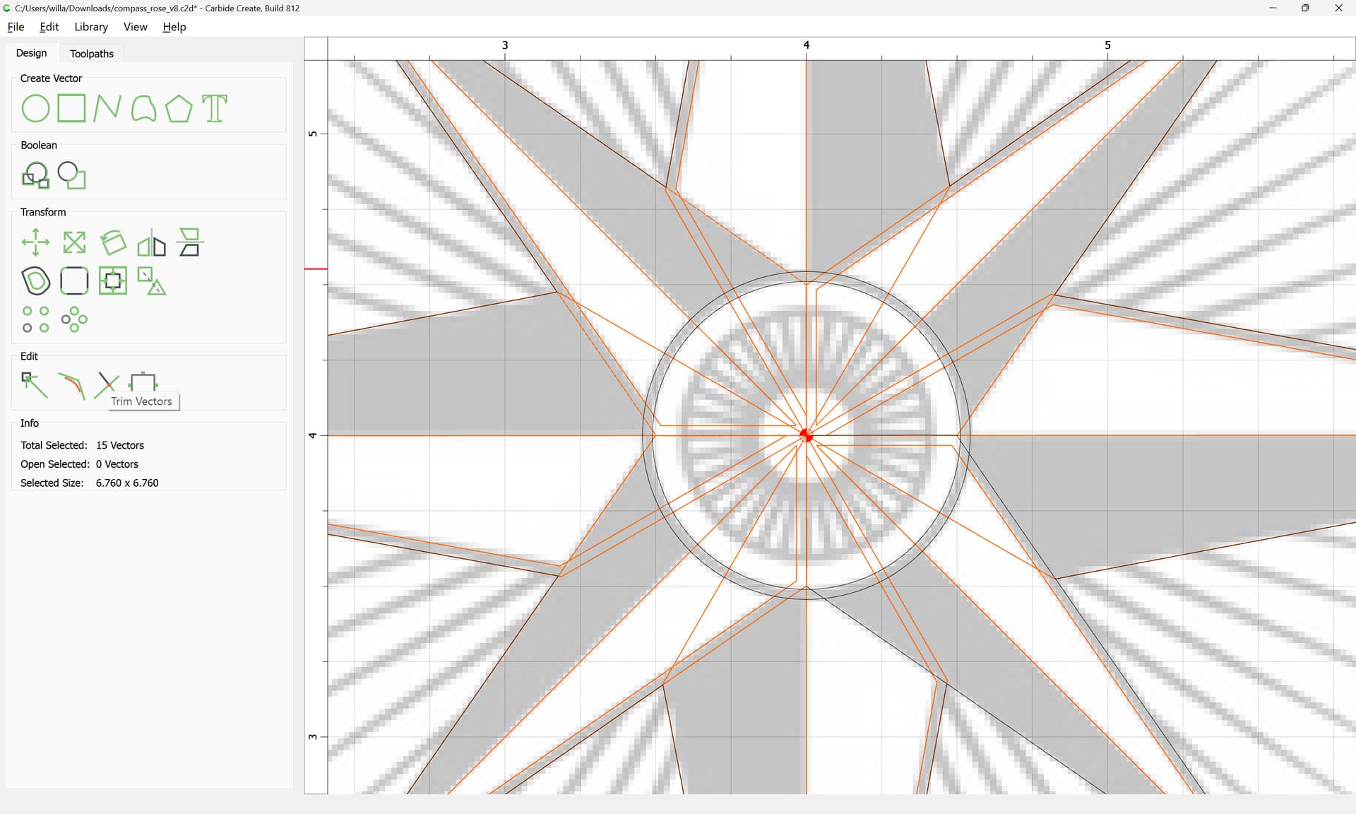
and the outer circle:

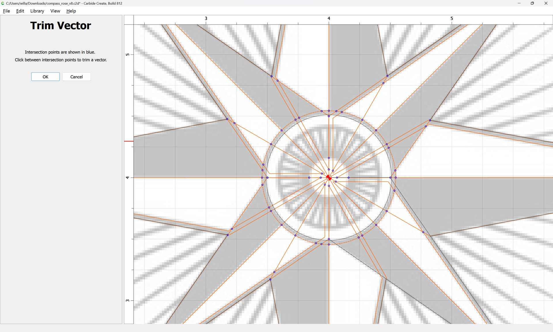
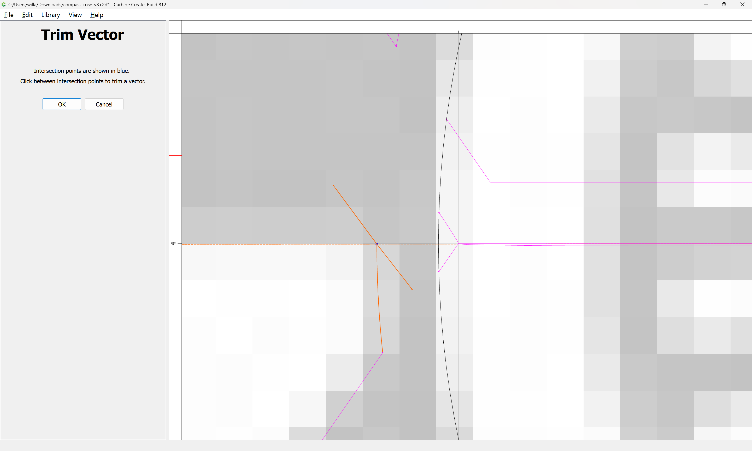
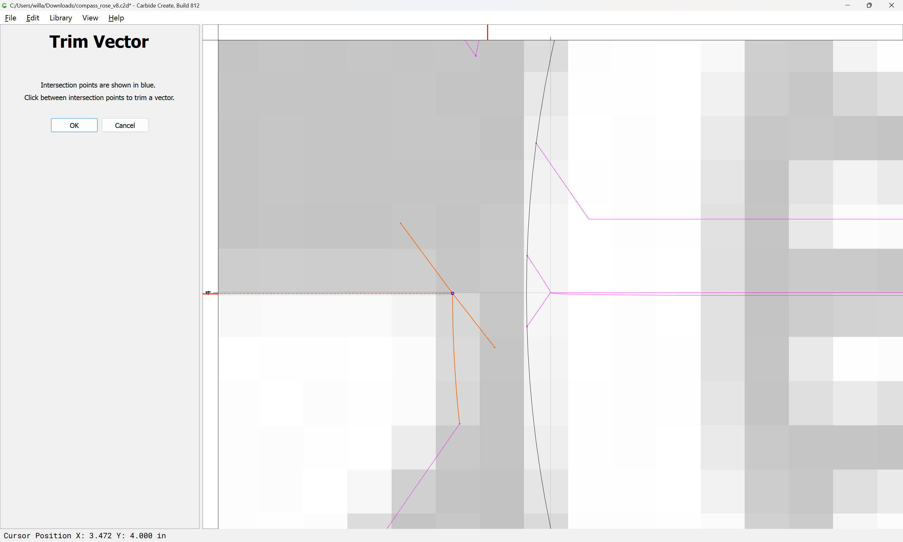
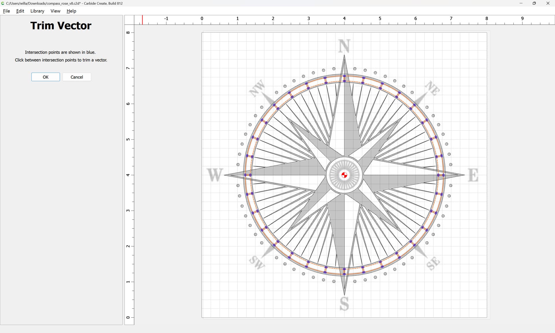
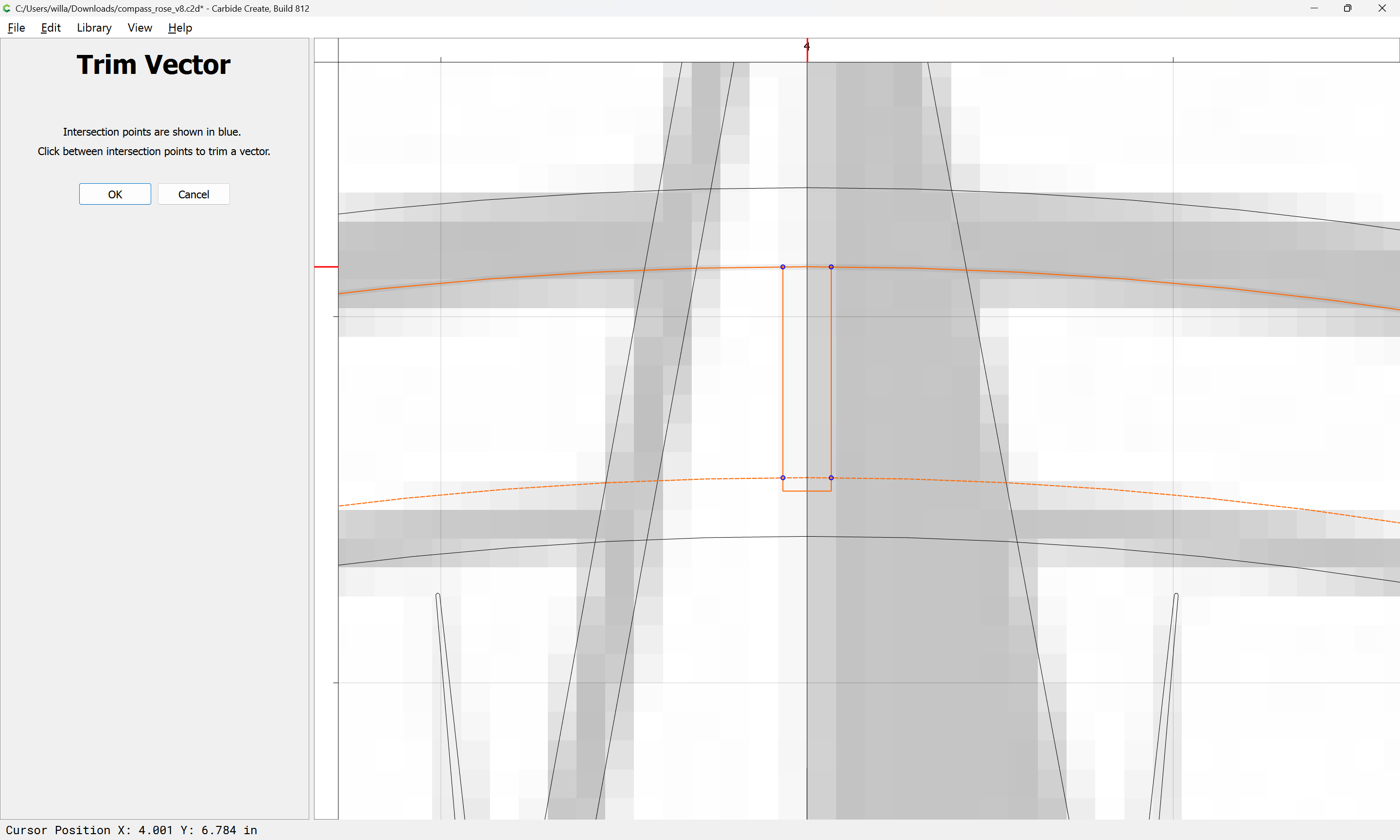
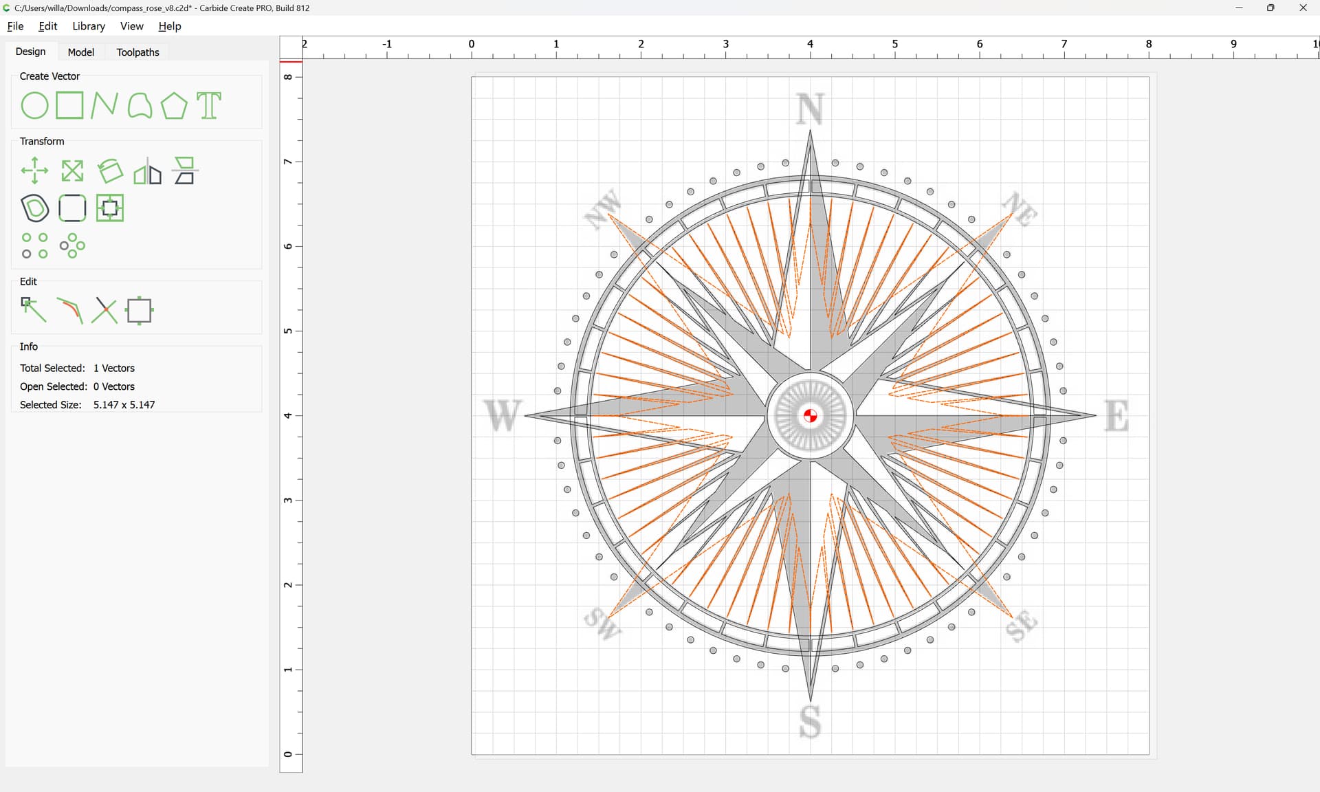
use Trim Vectors to remove what is not wanted:
but before doing that, back up and select each of the larger highlighting geometries:
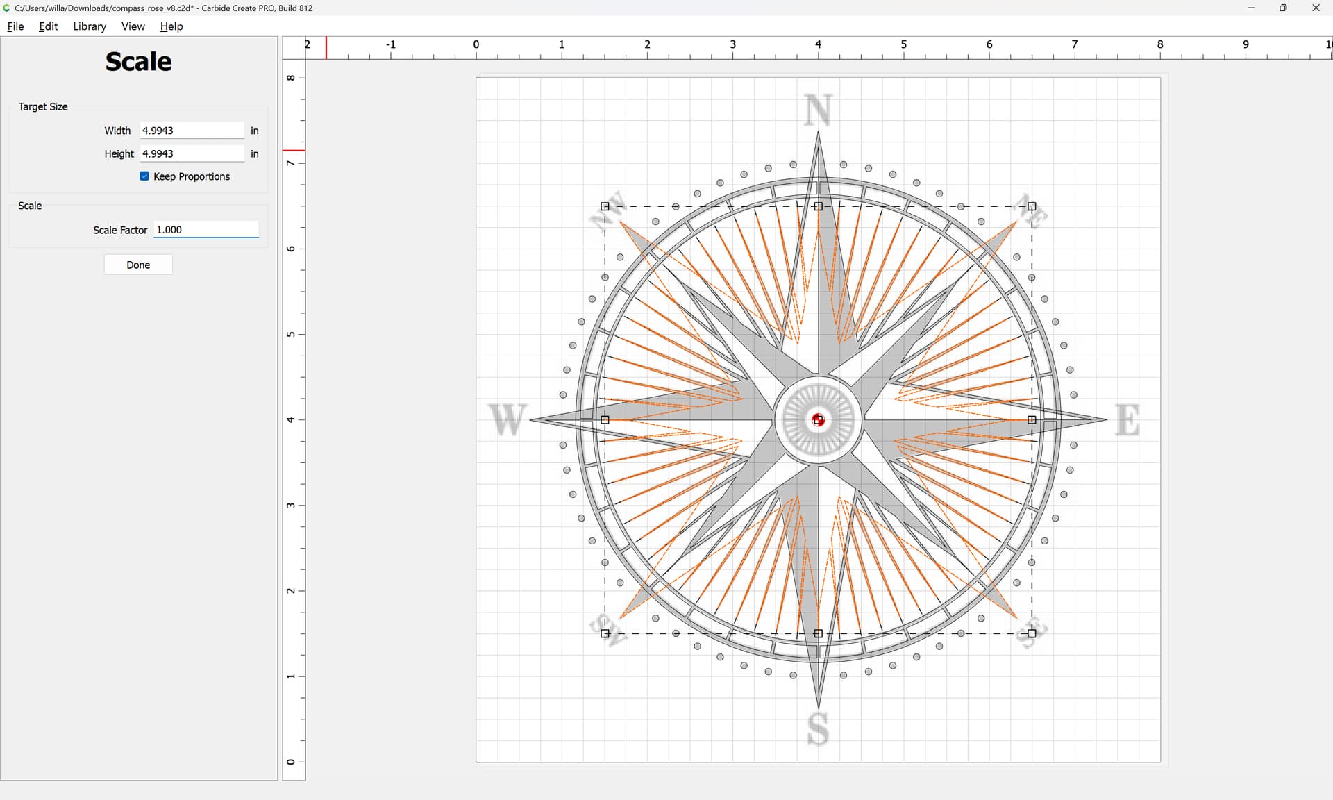
duplicate them:
and increase the size slightly:
Done
and drag each into alignment with the original and delete the original:

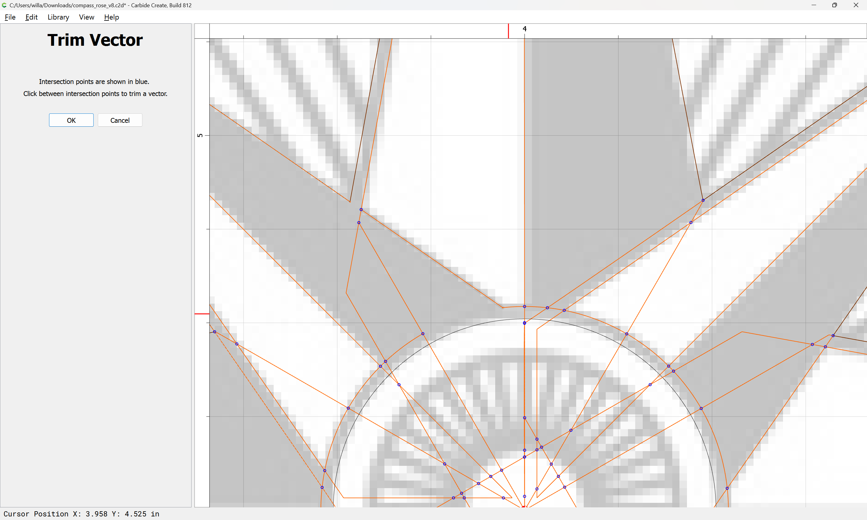
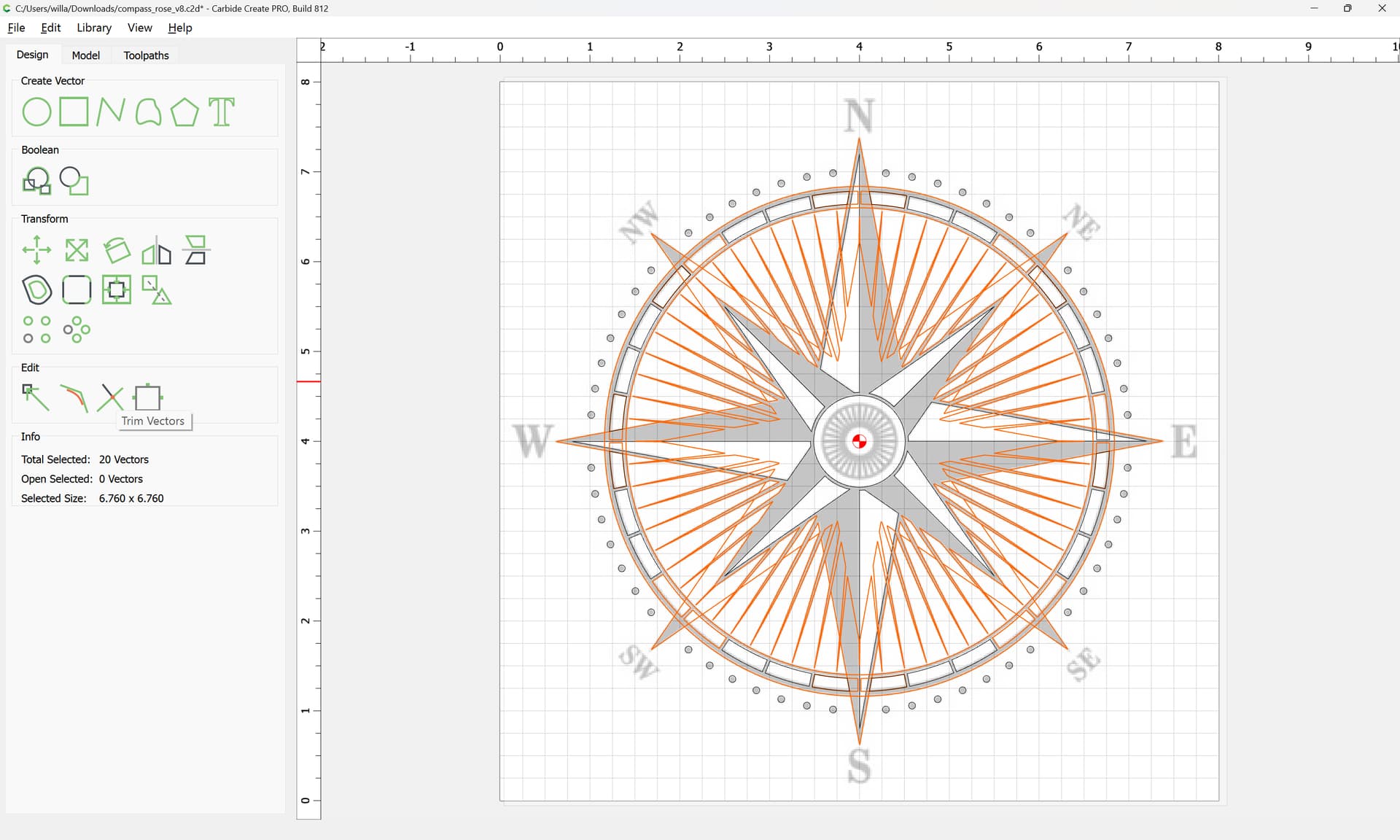
Repeat the selection:
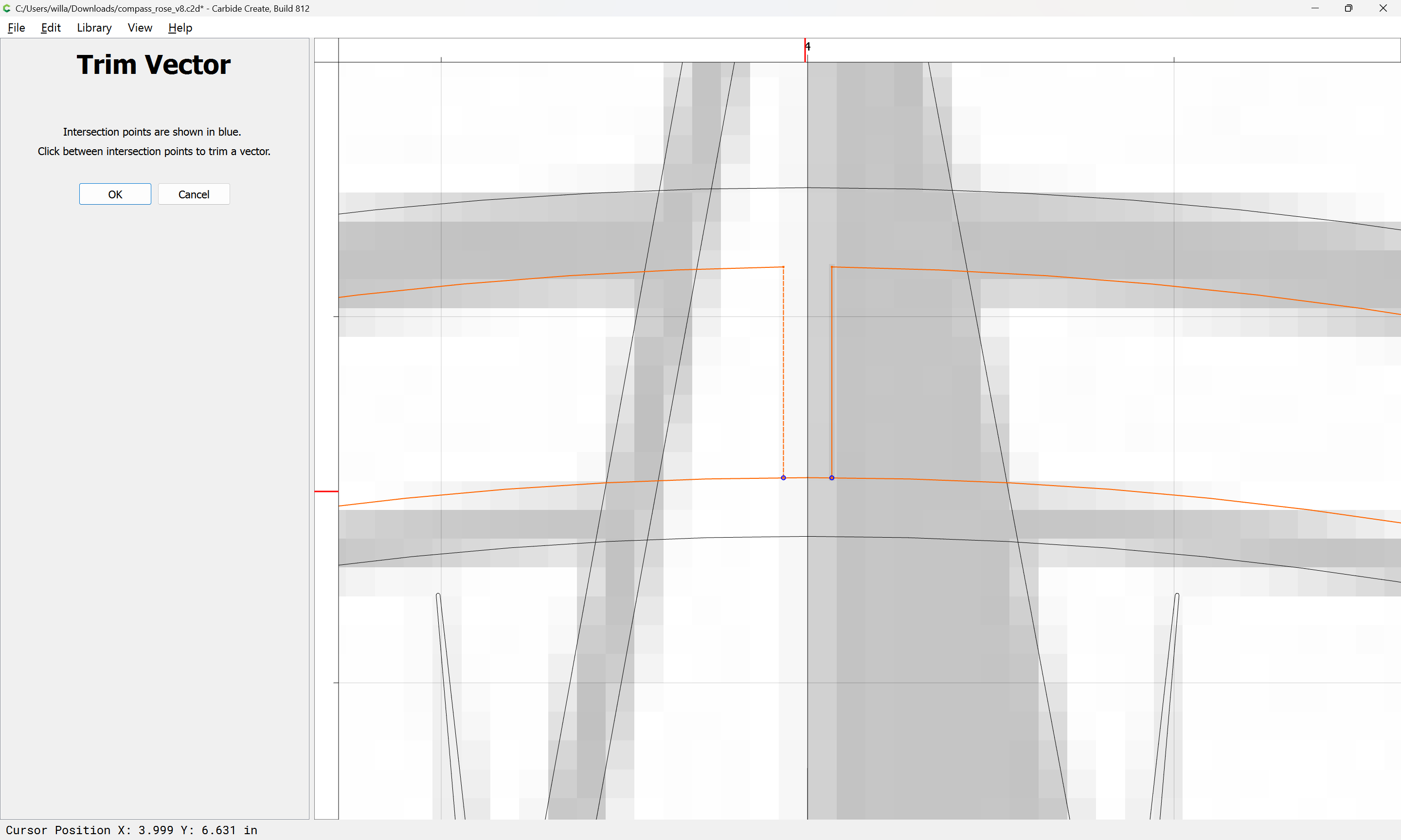
and use Trim Vectors:
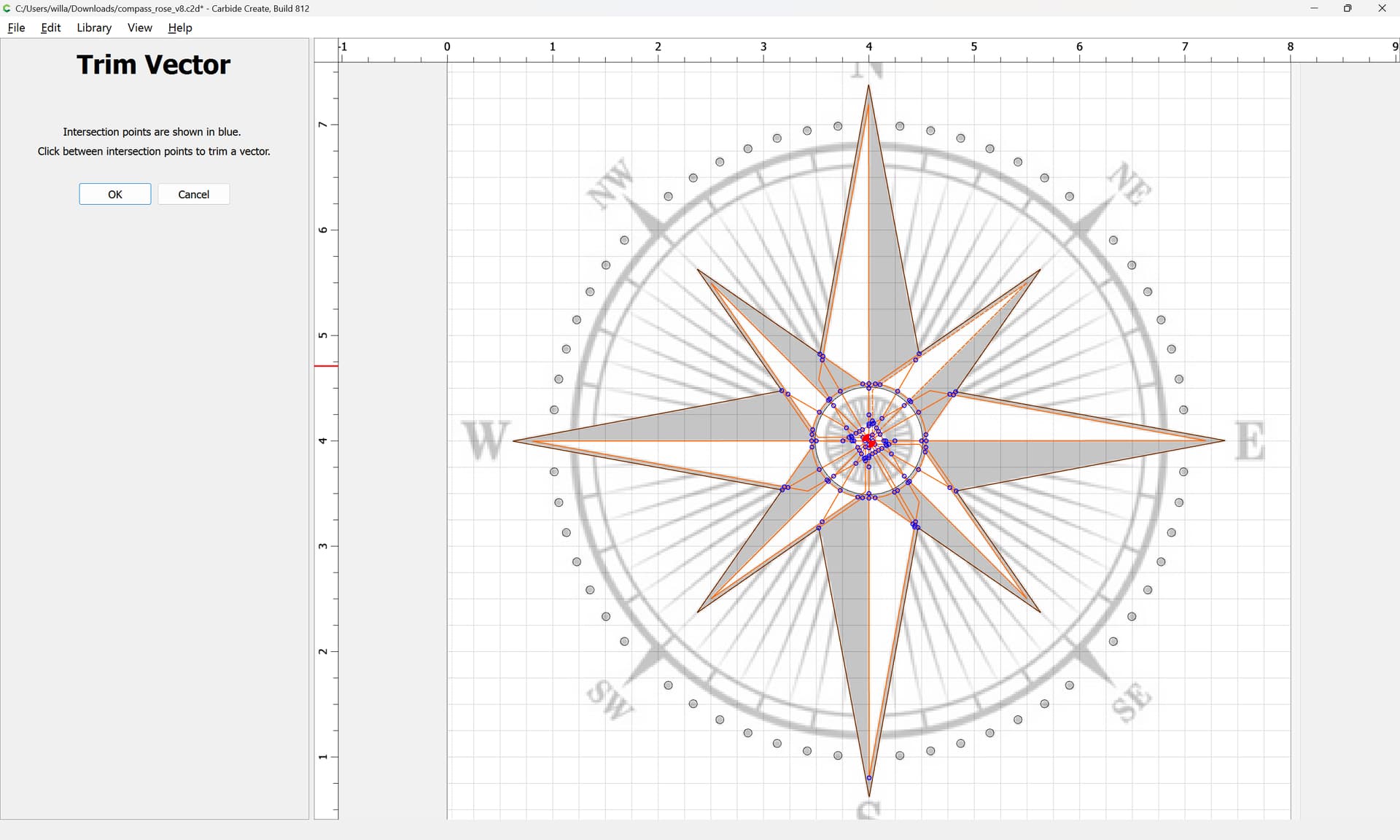
to remove what is not wanted:


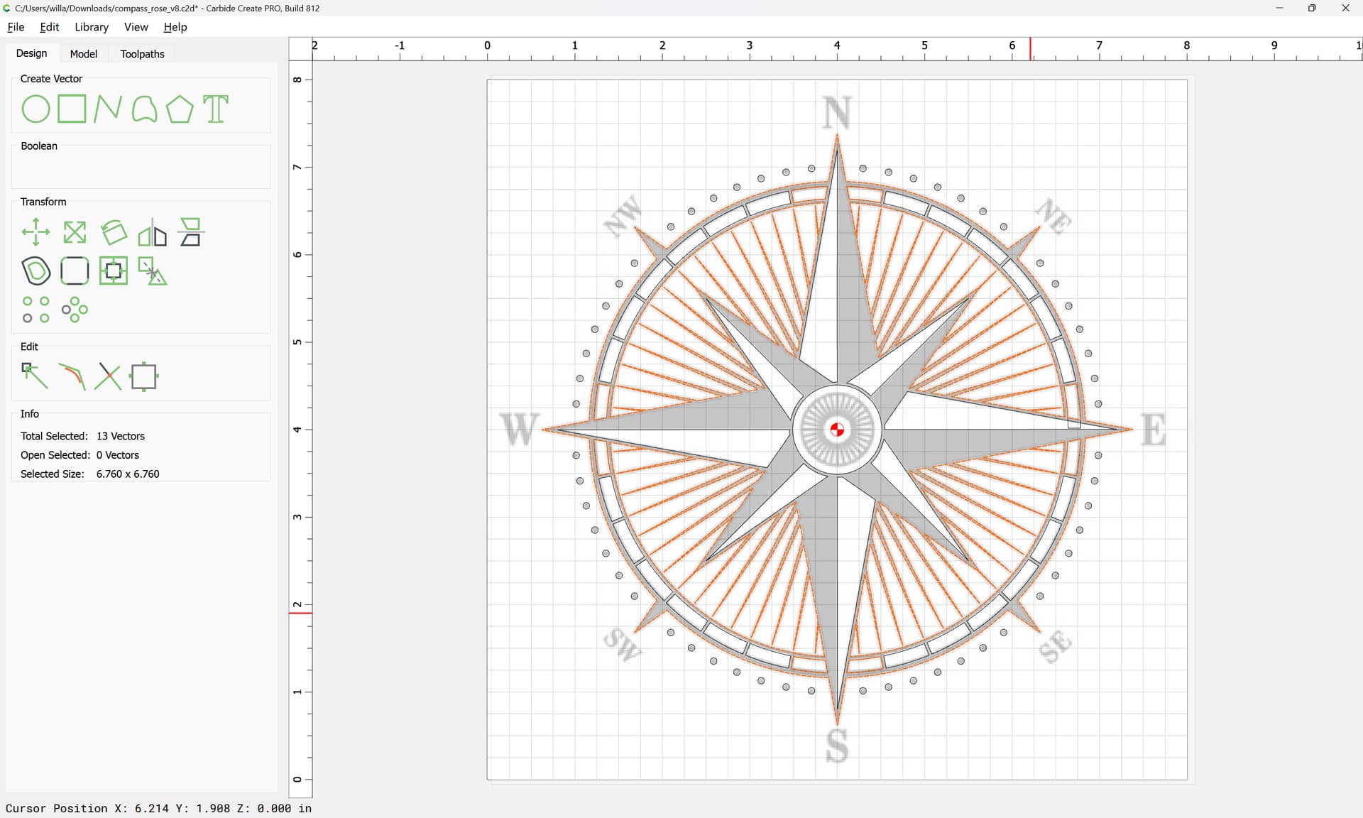
Continuing until one arrives at:
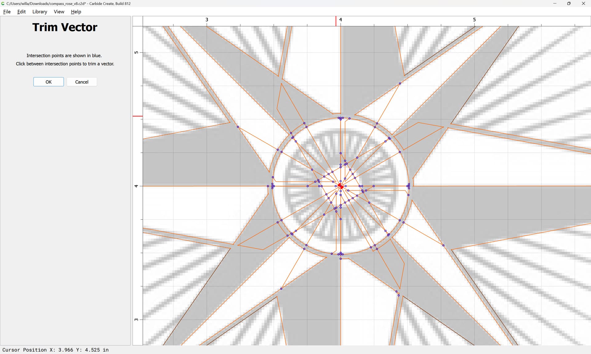
Done
Note that if a line was missed:
It may be addressed by drawing in an addition line:
Then selecting the involved elements:

and re-doing Trim Vectors:
OK
and then cleaning up.
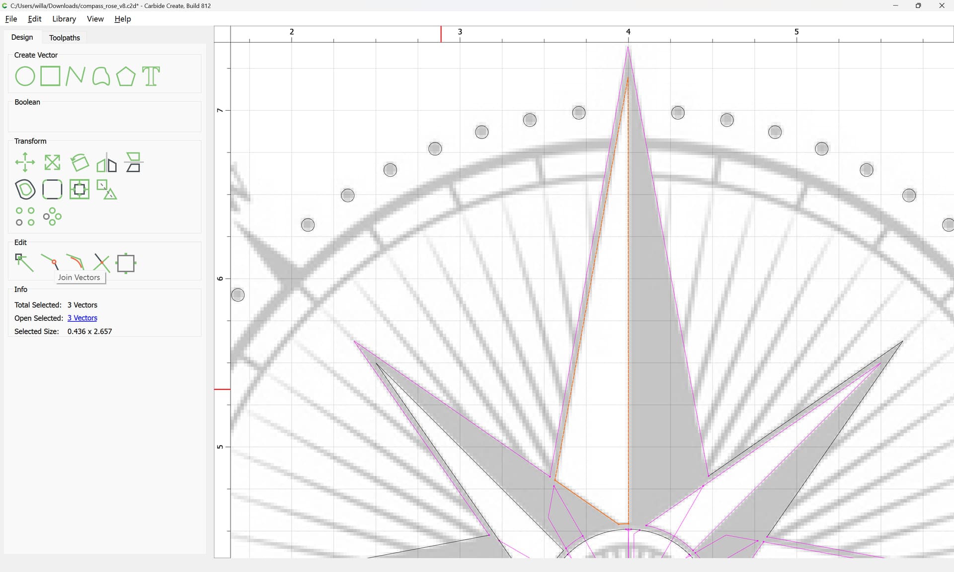
Select the interior geometries for each highlight:
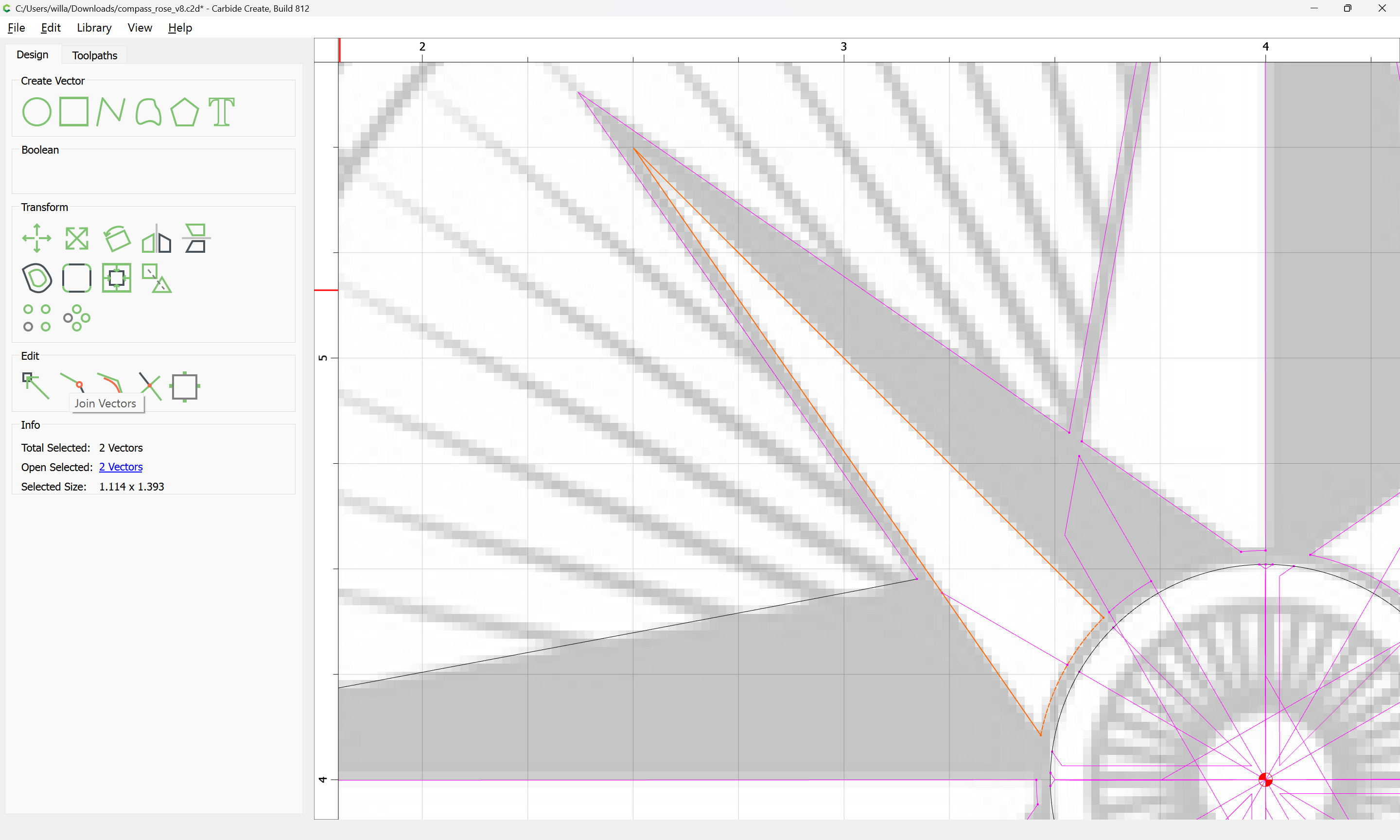
and use Join Vectors:
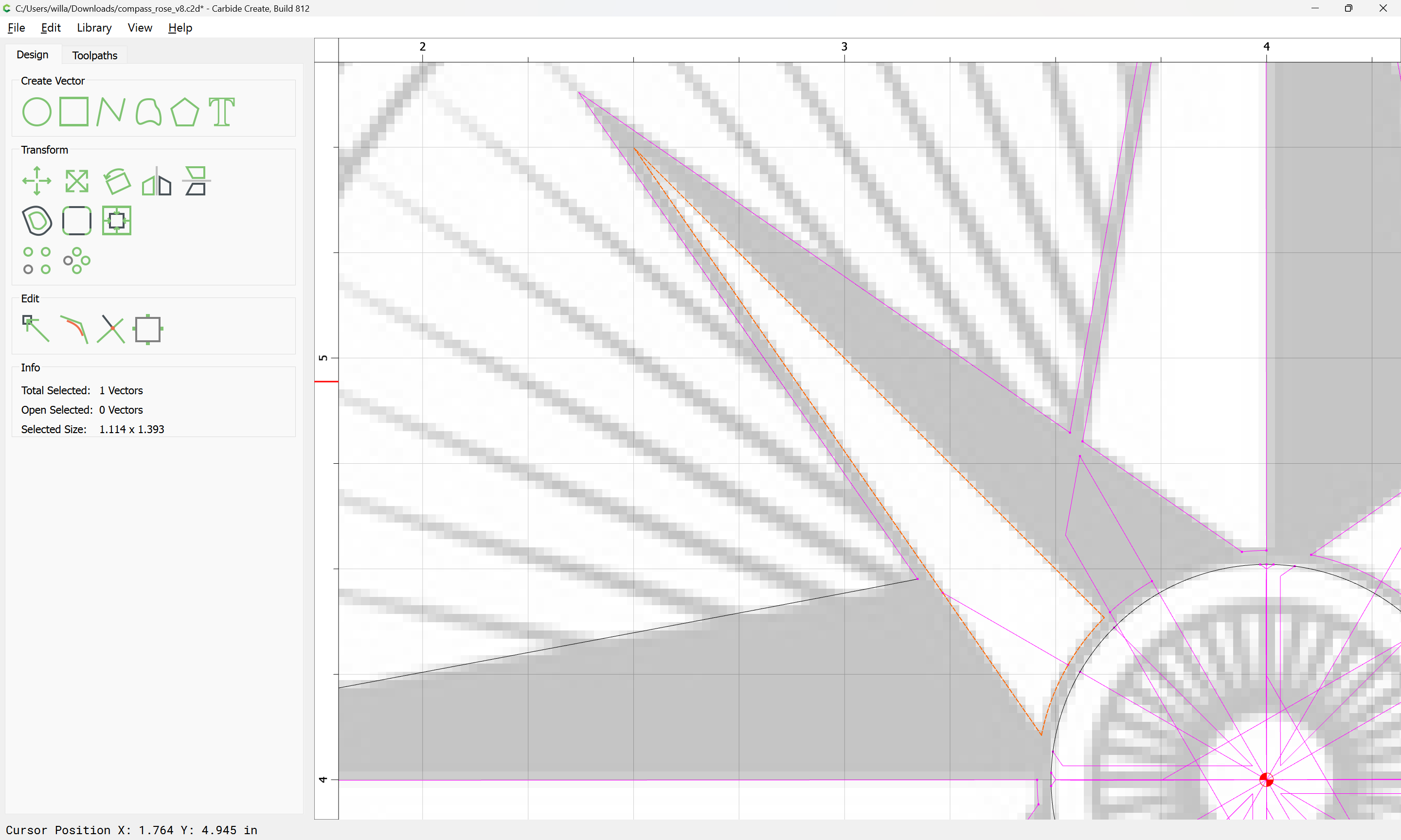
to close.
Repeat
Some may result in a dialog such as:
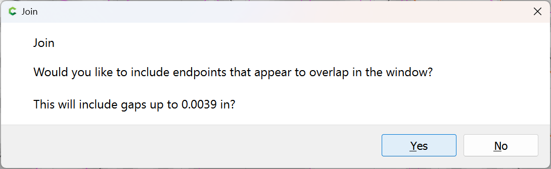
until one arrives at:
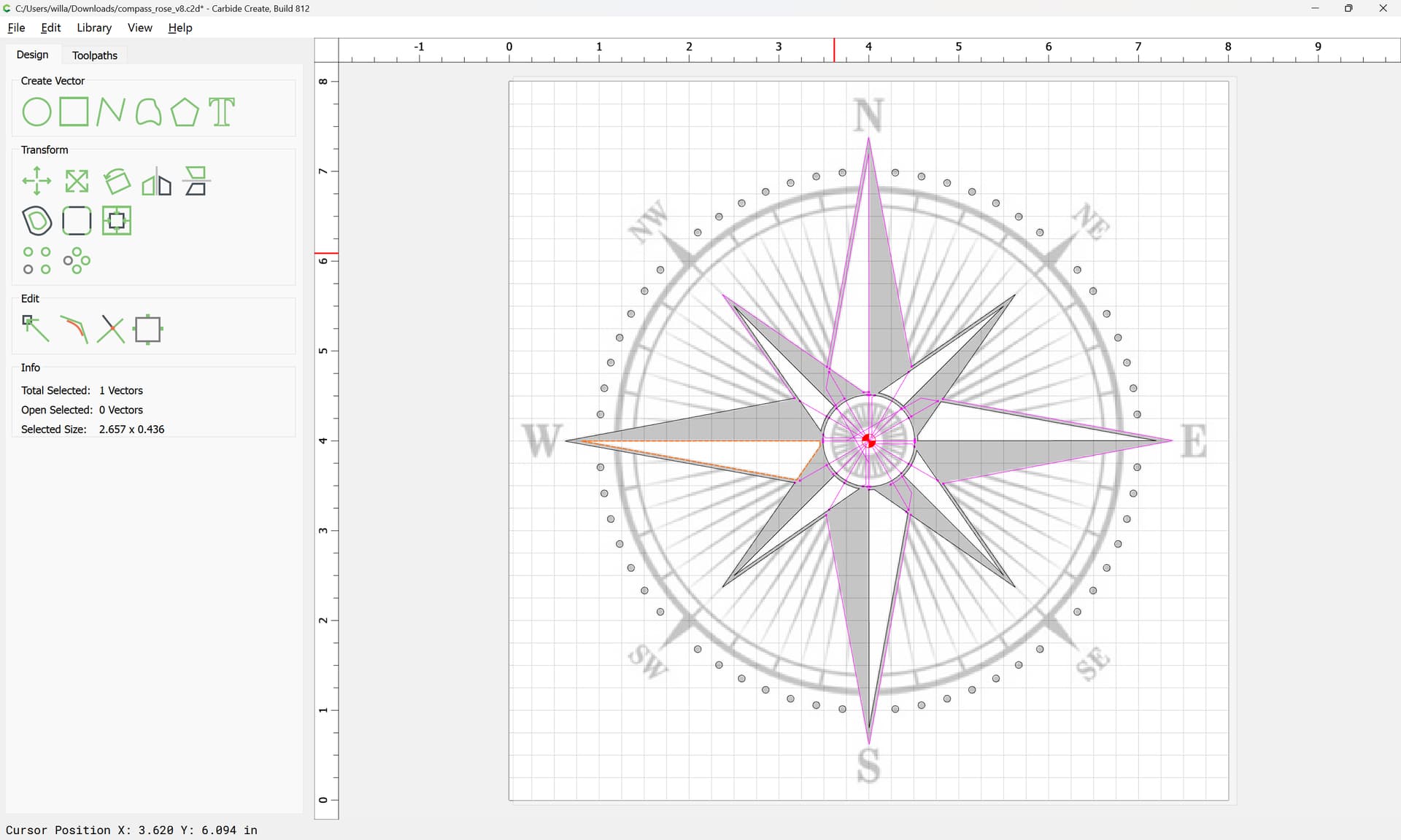
Select all the Open Vectors:
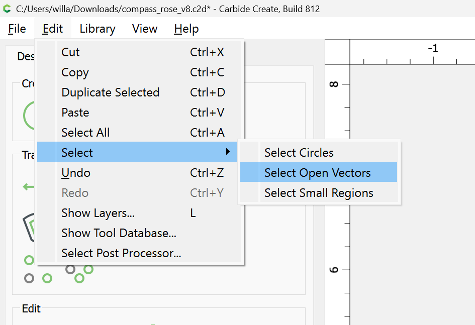
and delete them to arrive at:
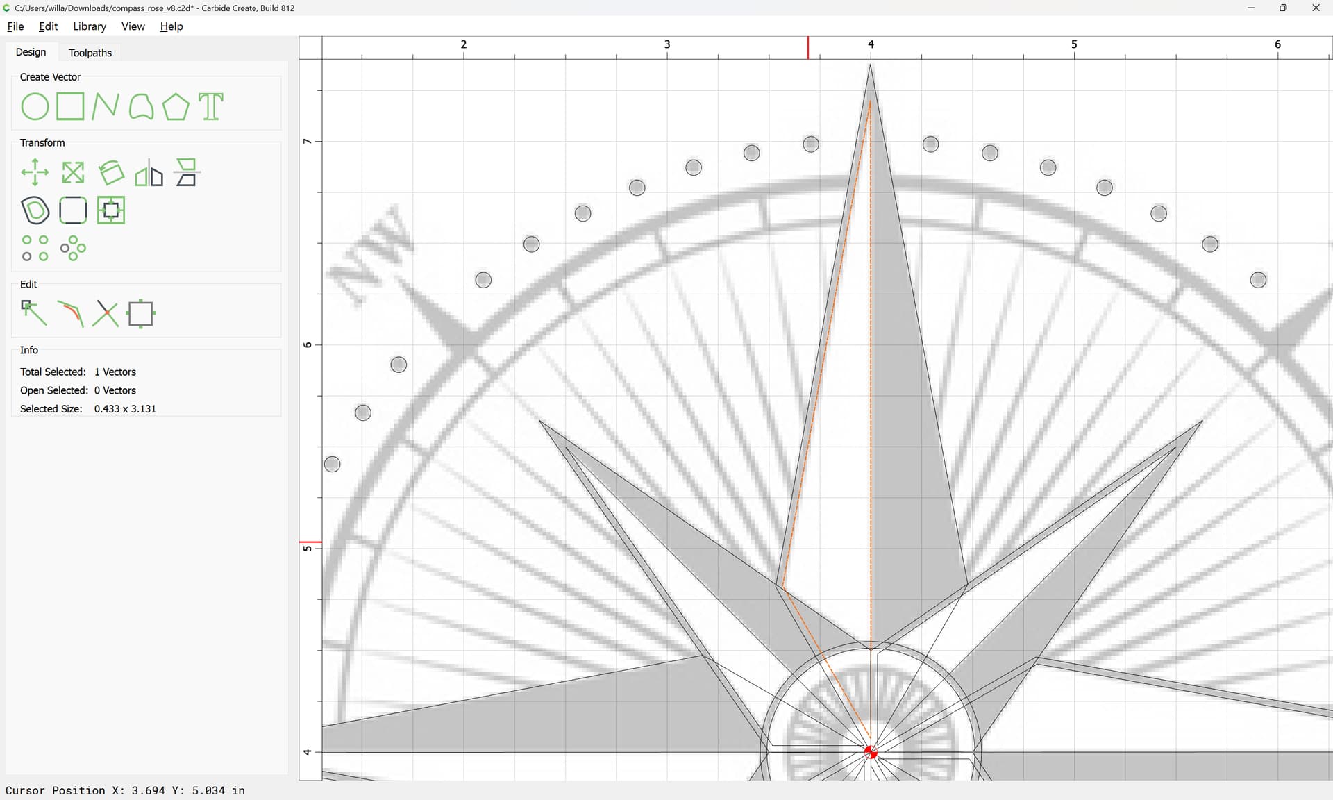
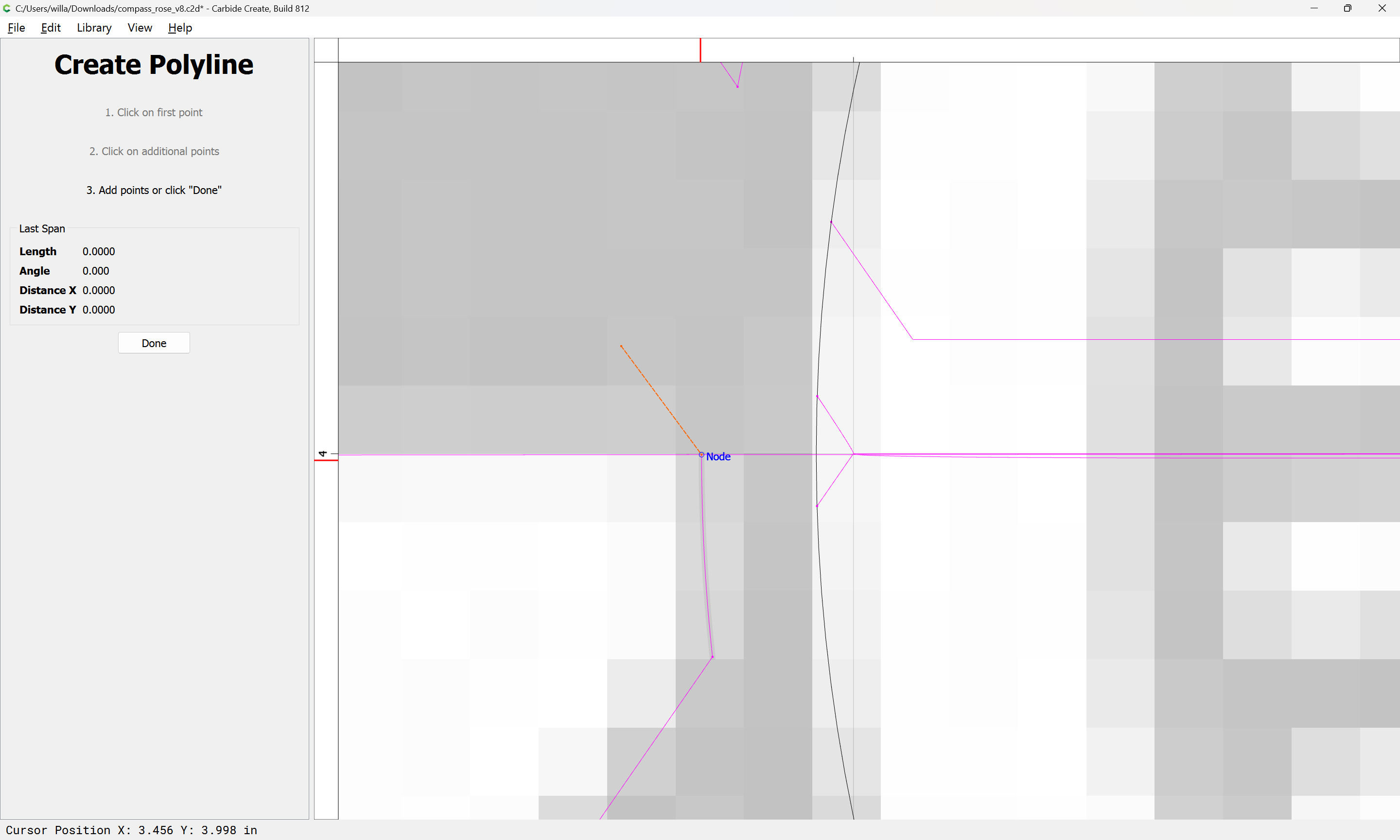
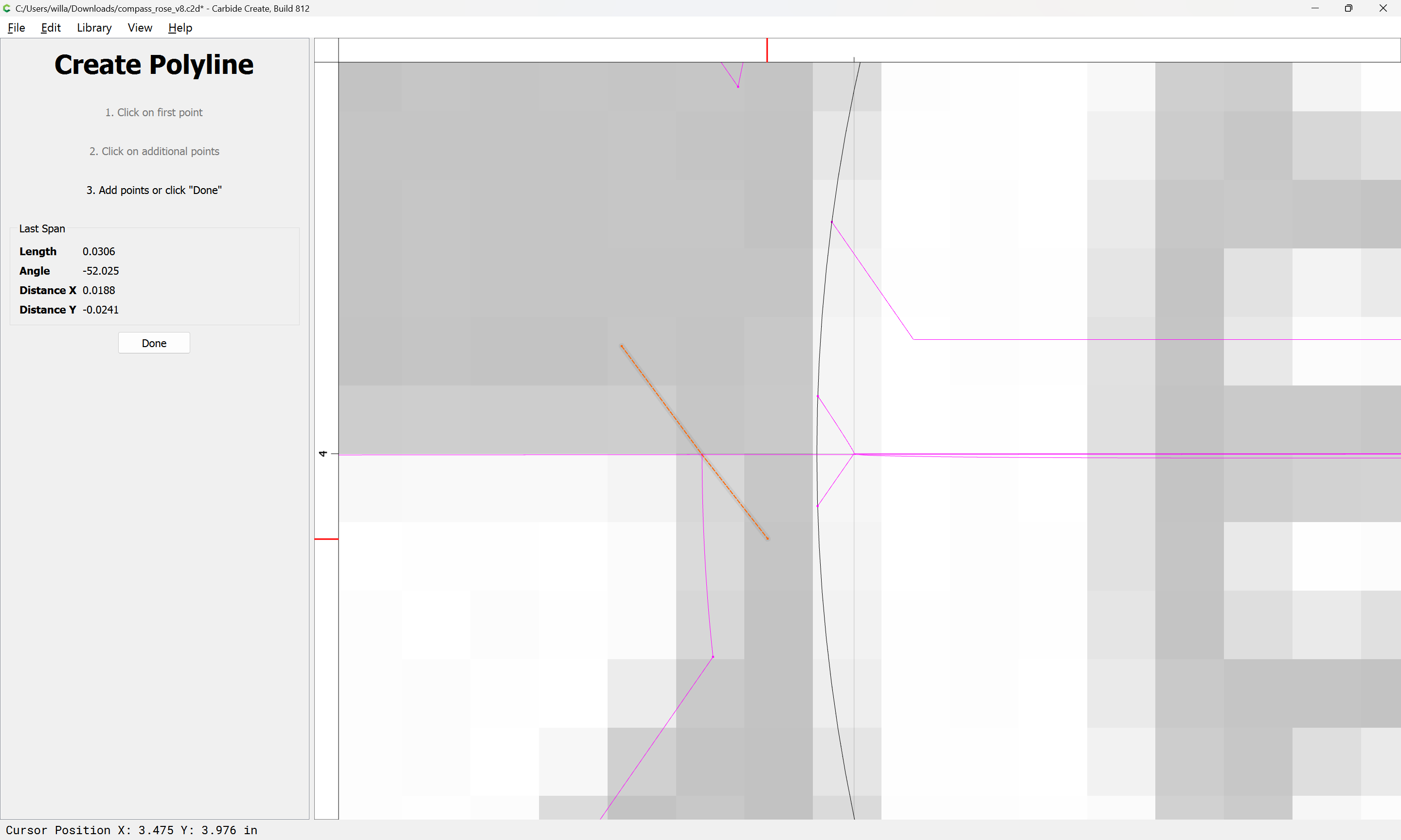
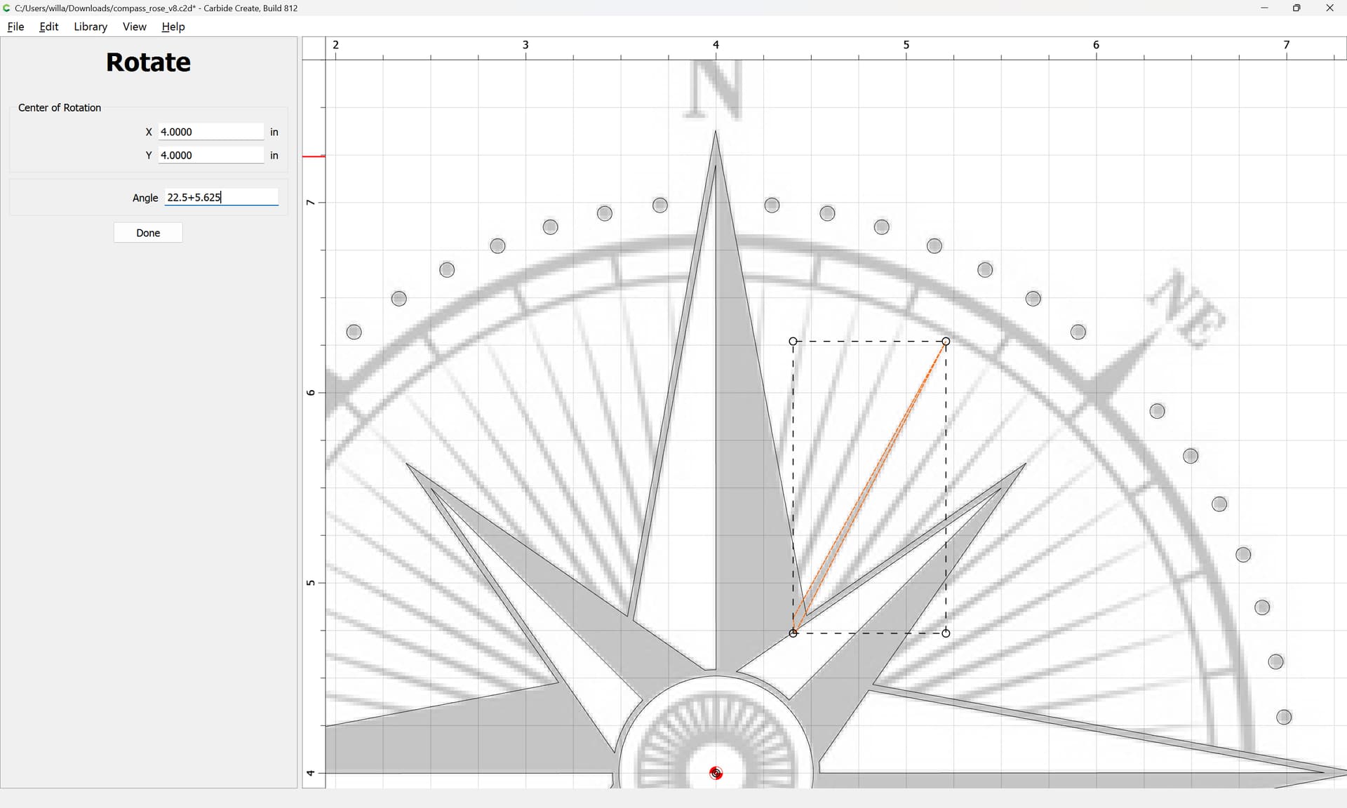
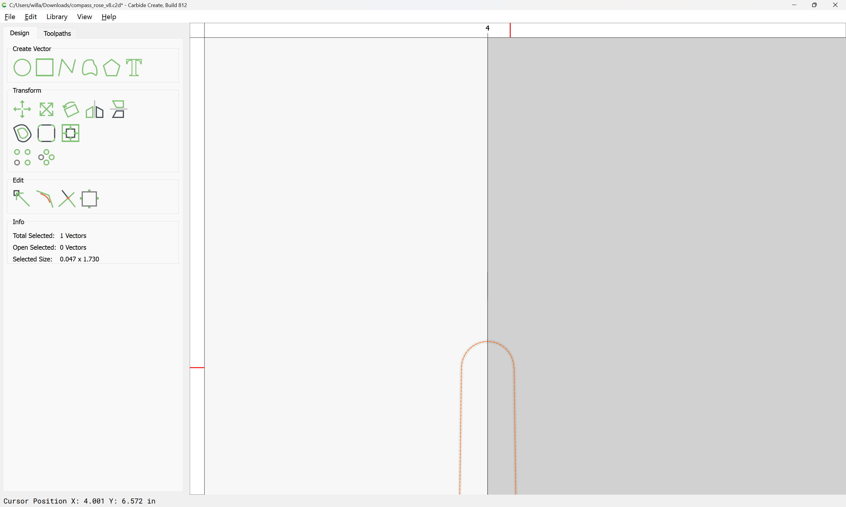
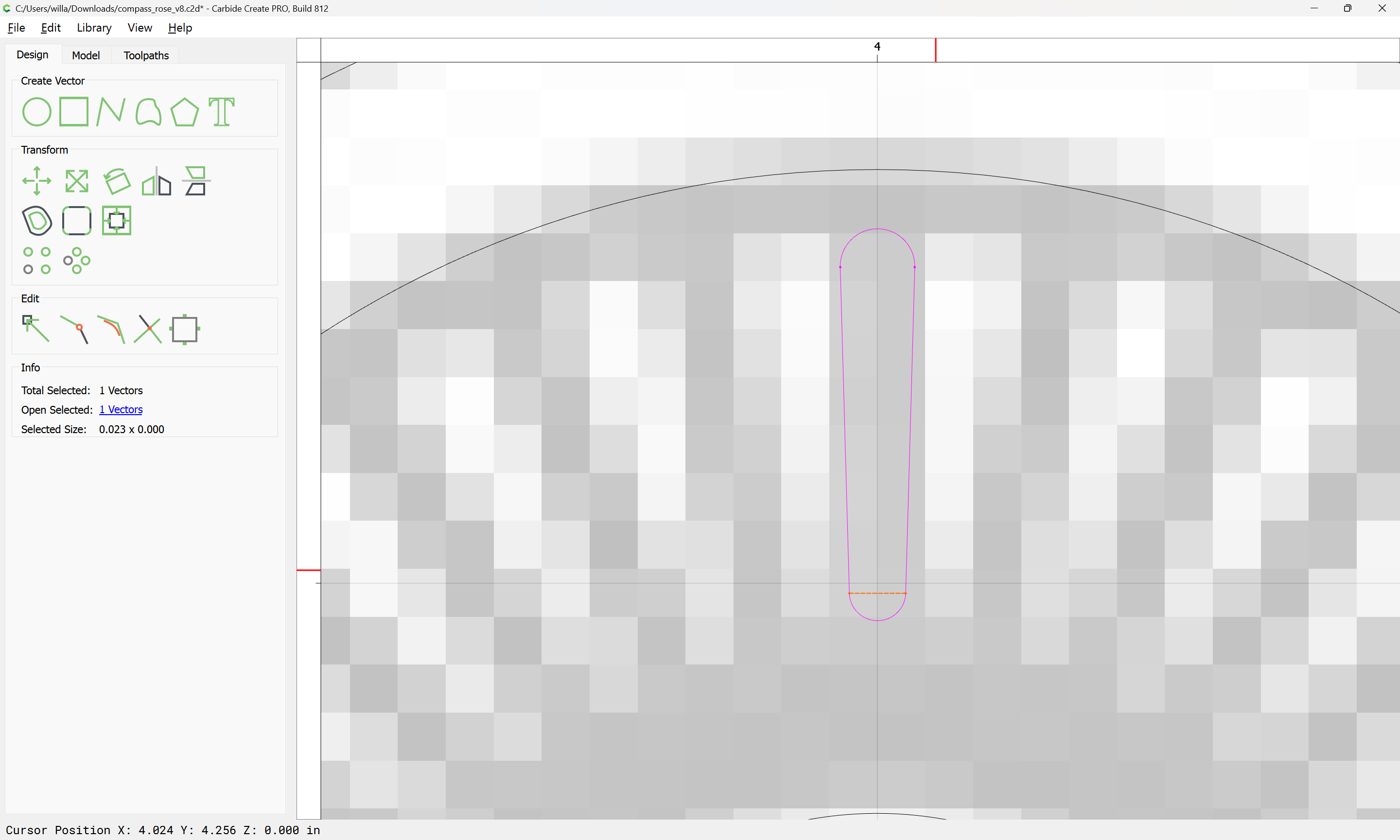
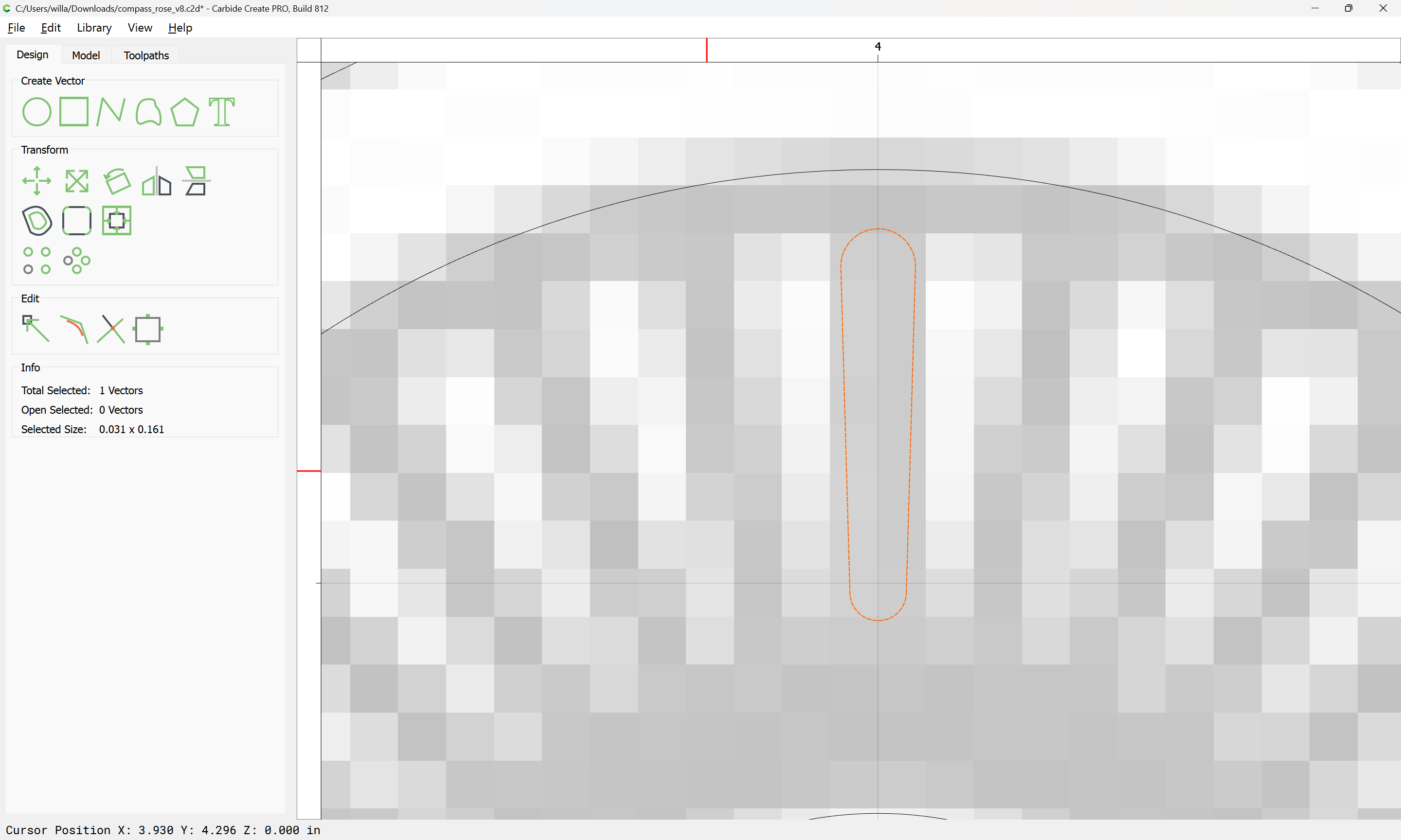
Draw in one of the very narrow lines:
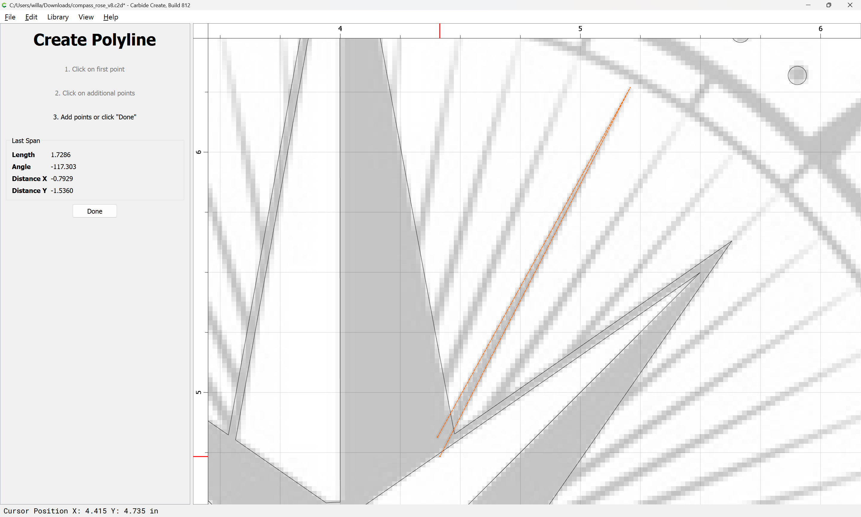
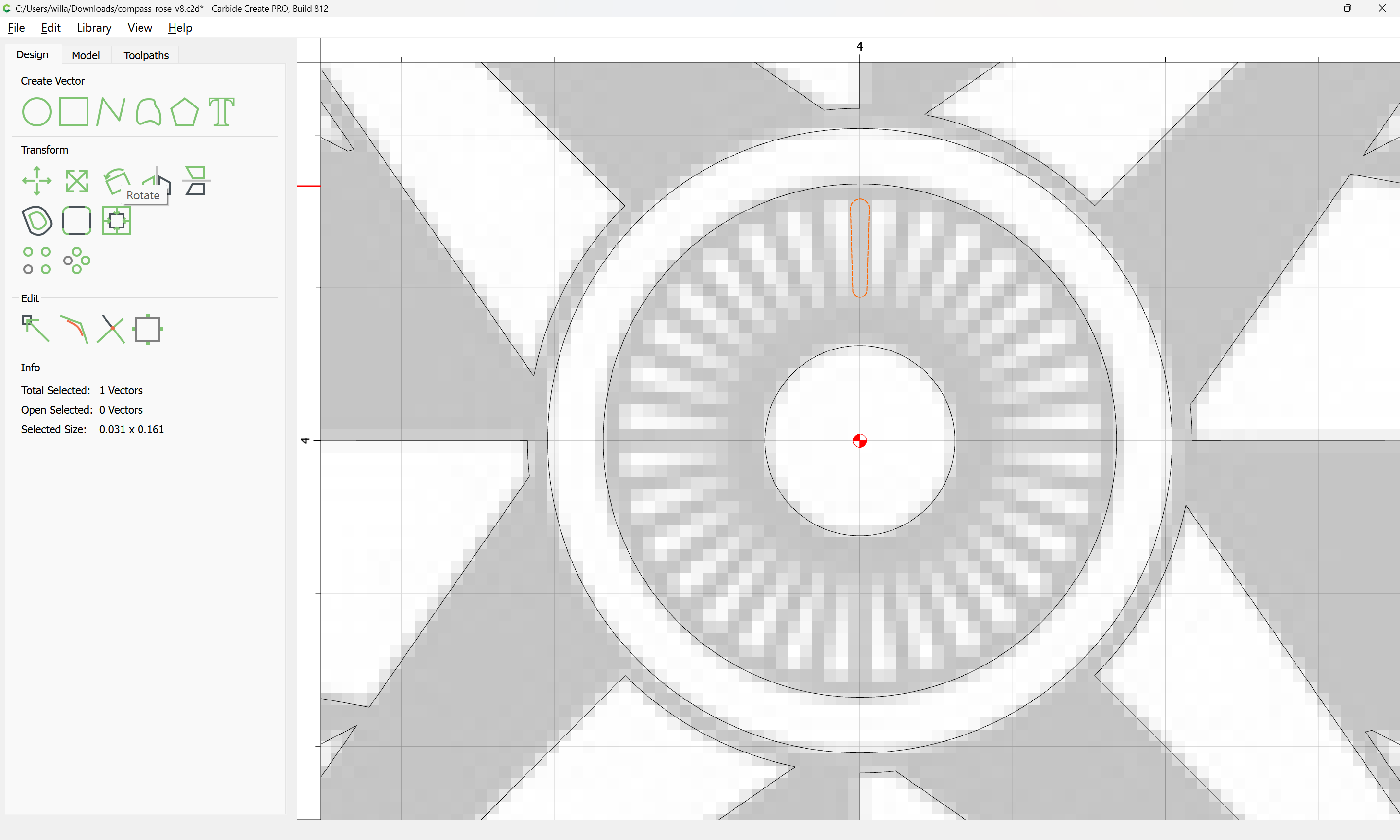
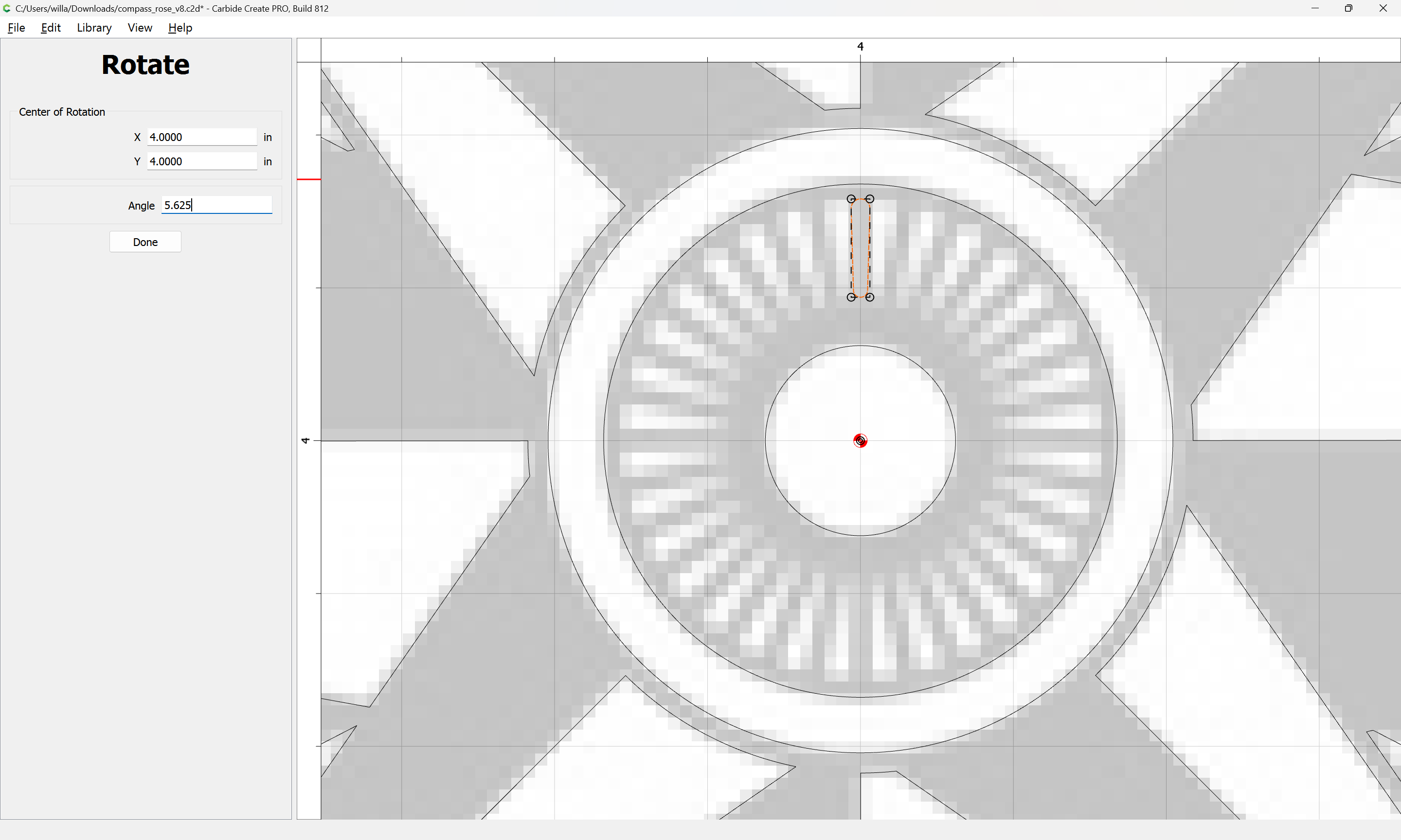
and as before, rotate it to fully vertical — since there are 64 dot positions around the perimeter this is obviously 22.5 + 5.625 degrees:
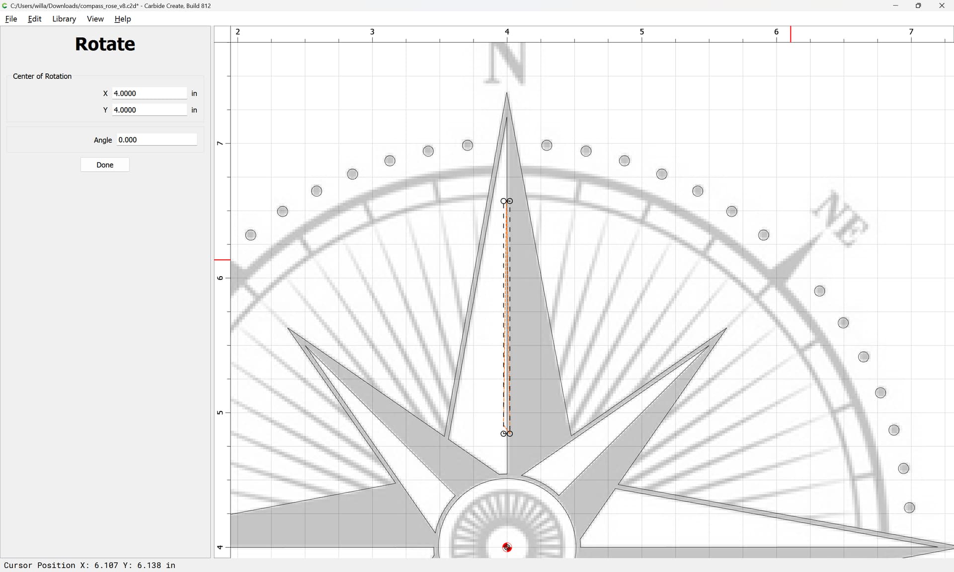
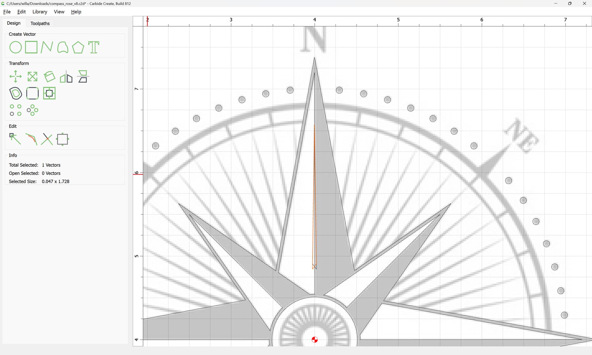
Done

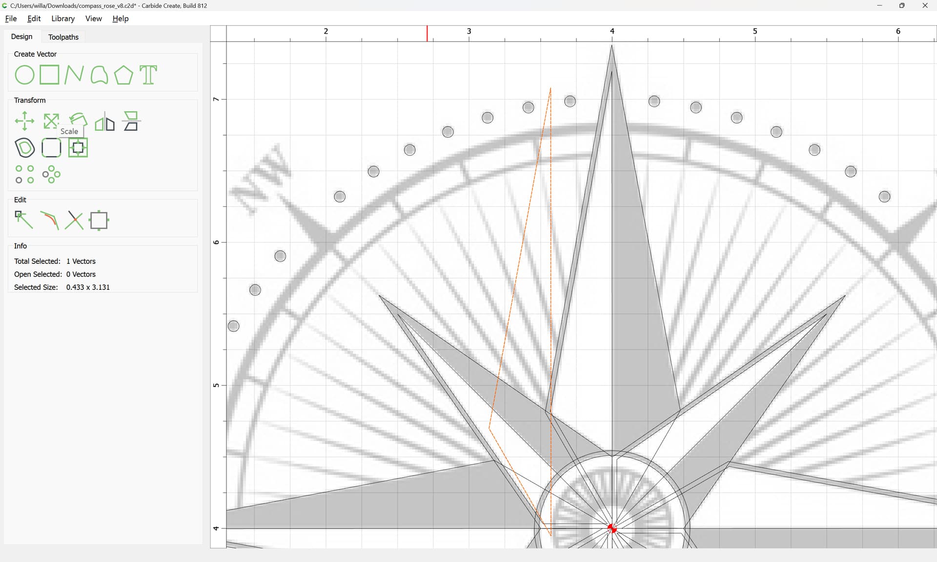
As before we duplicate it in place and mirror the duplicate:

Then select and union:
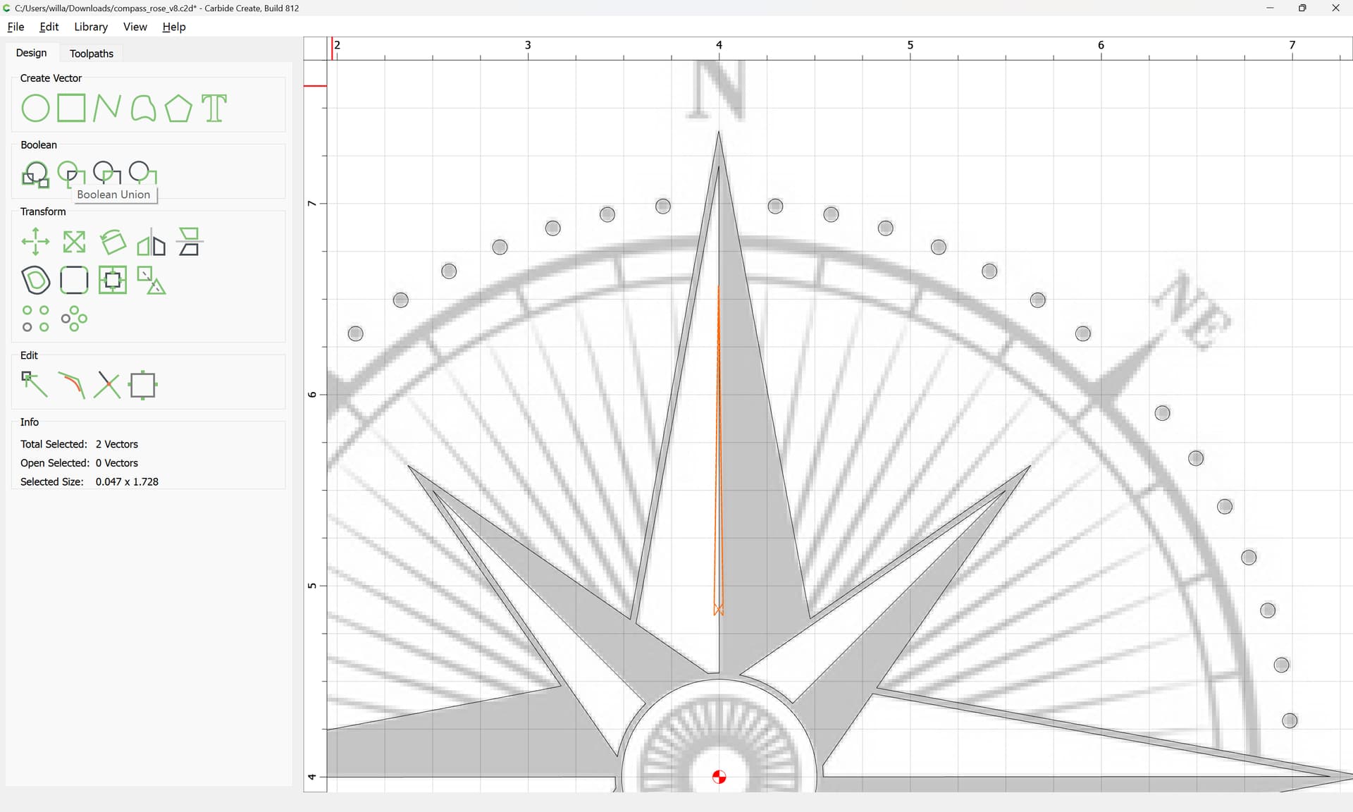
OK

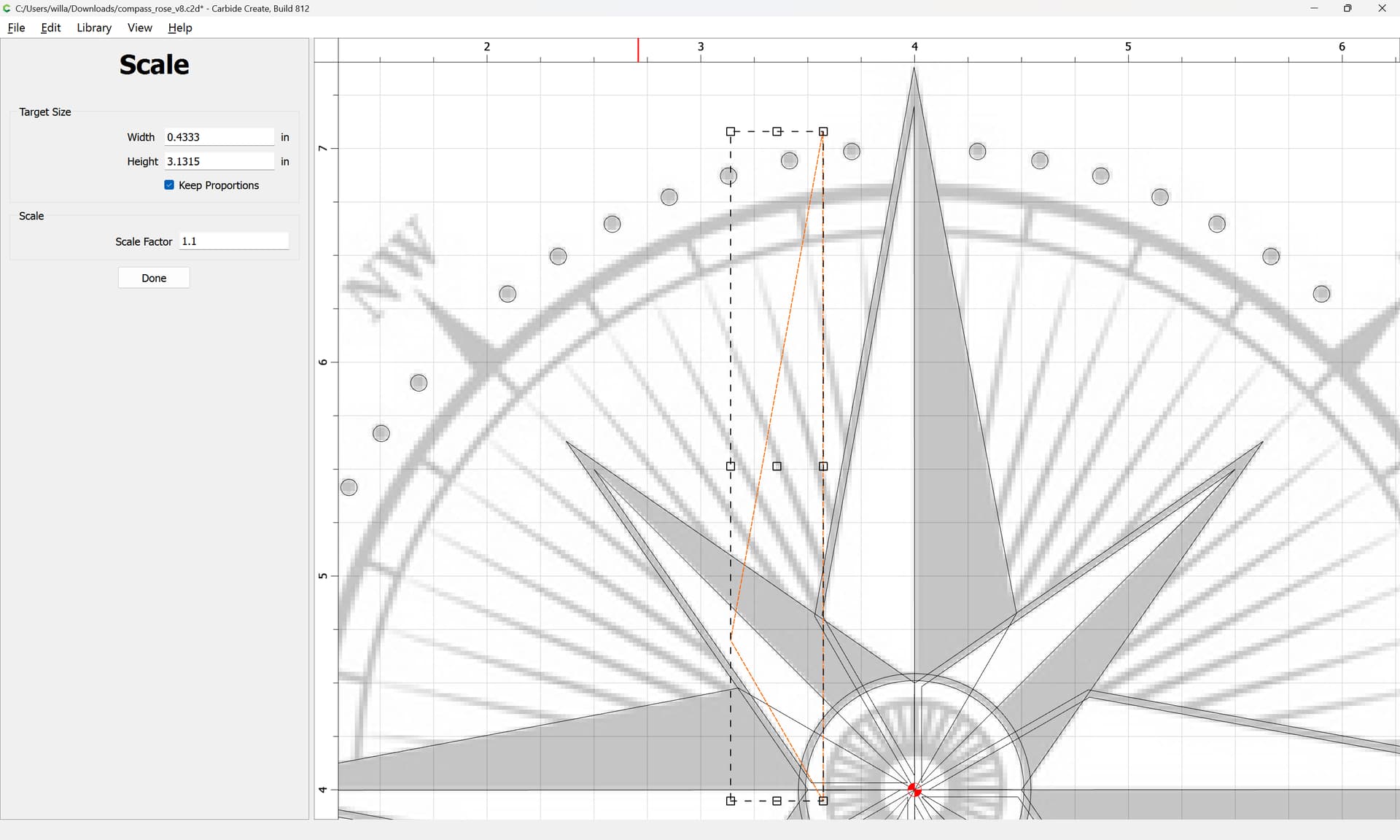
adjust the shape so that it may be easily cut:
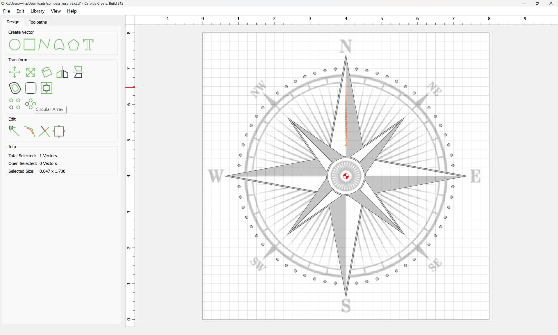
and then use a Circular array to duplicate around the design:
OK
Add the perimeter to the selection:

and use Boolean Union:
OK
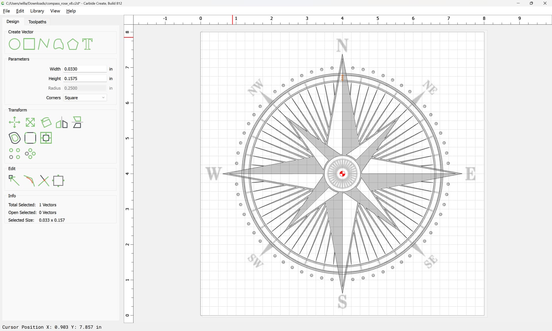
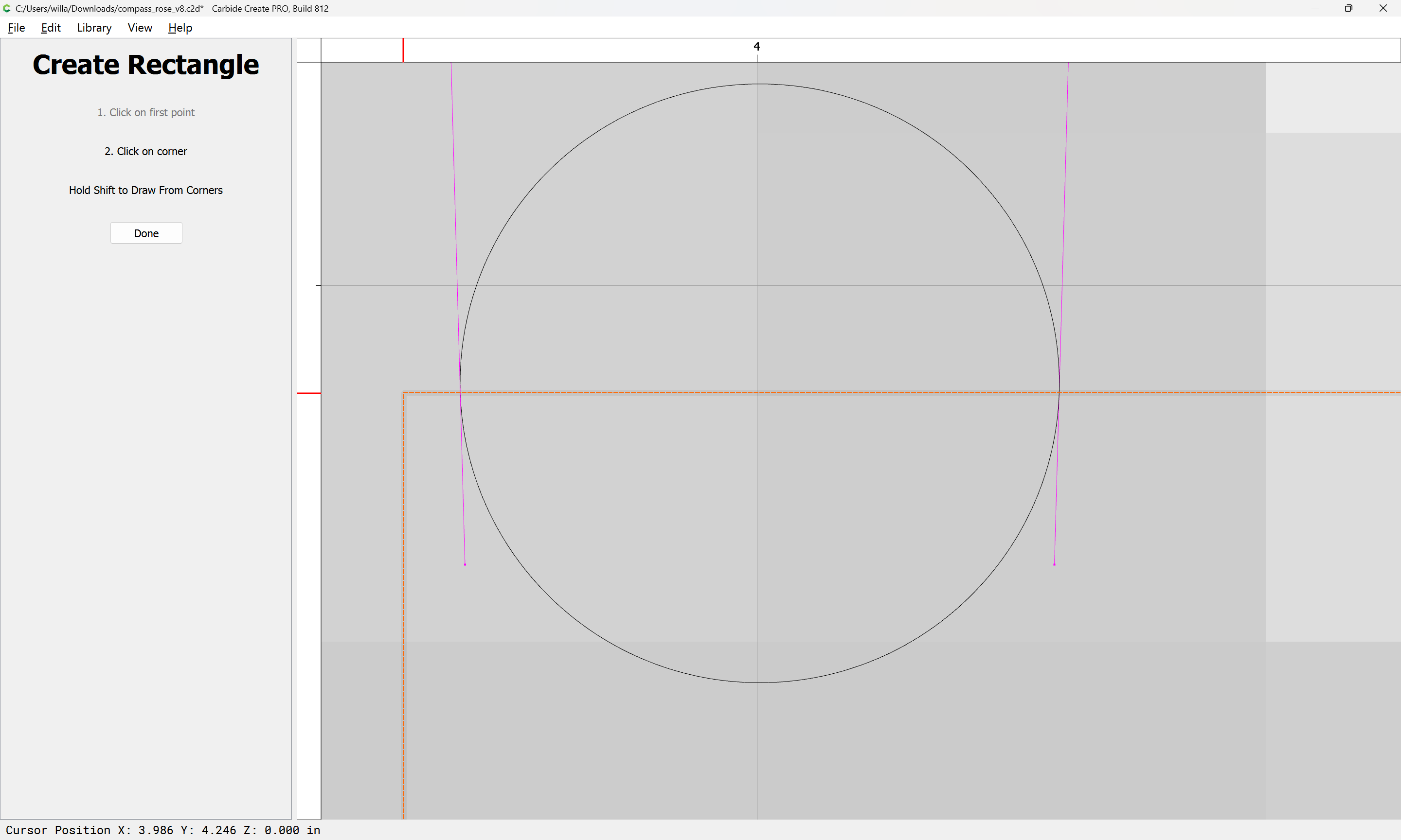
Draw in the geometry for the circles:
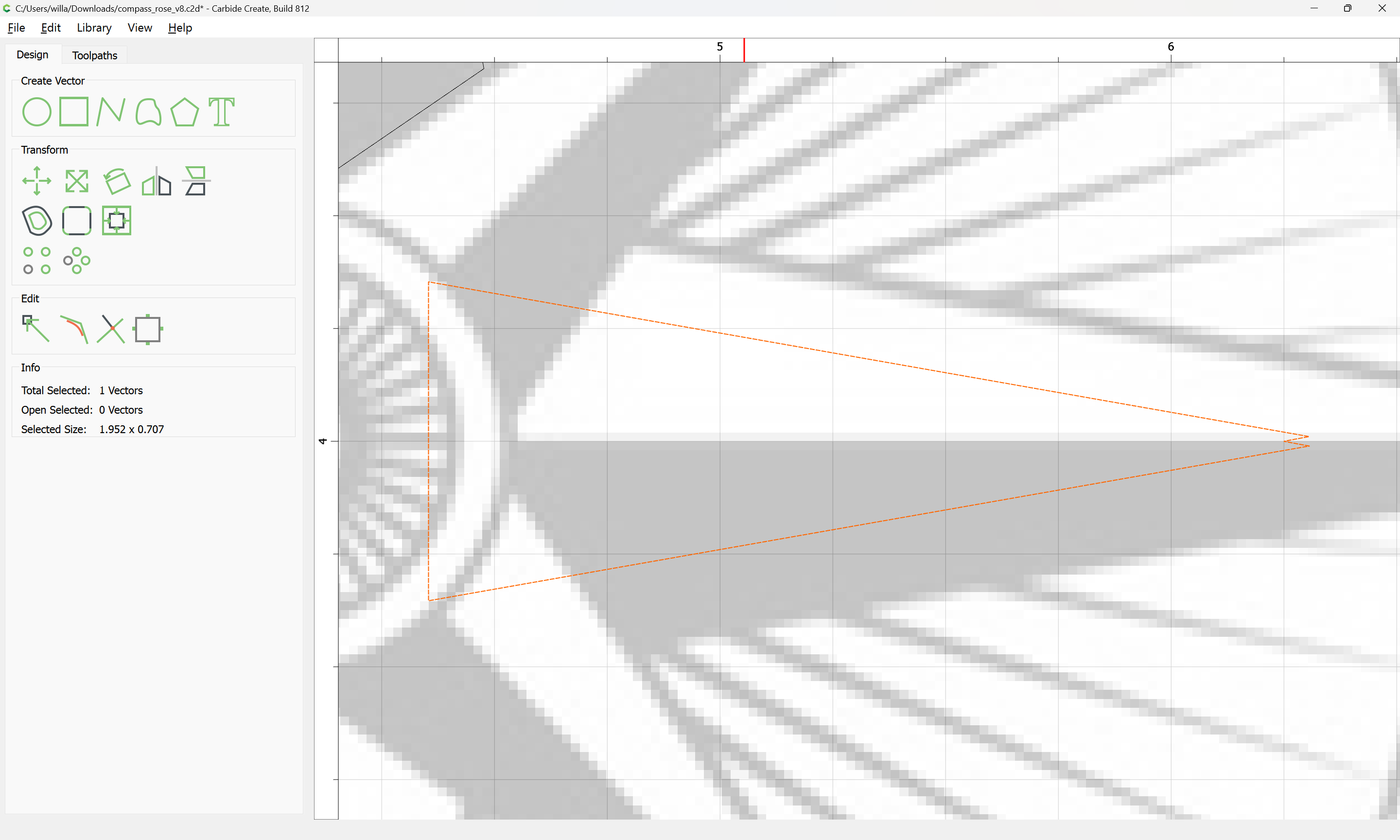
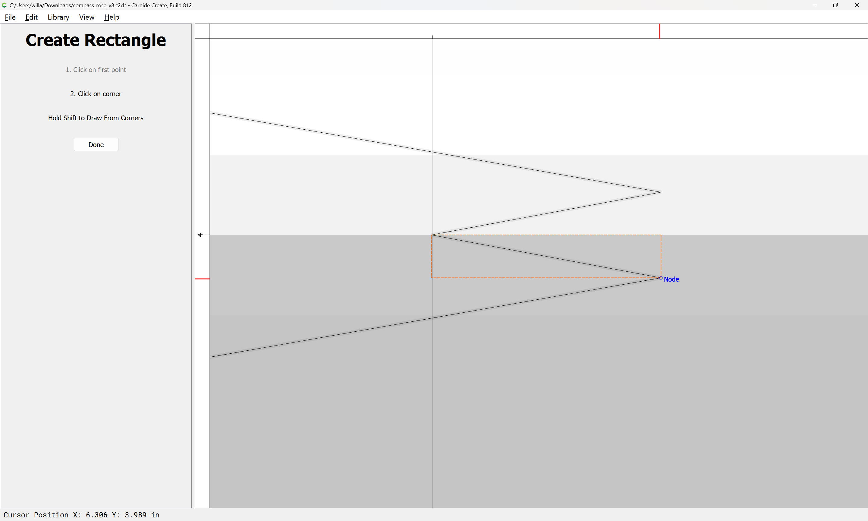
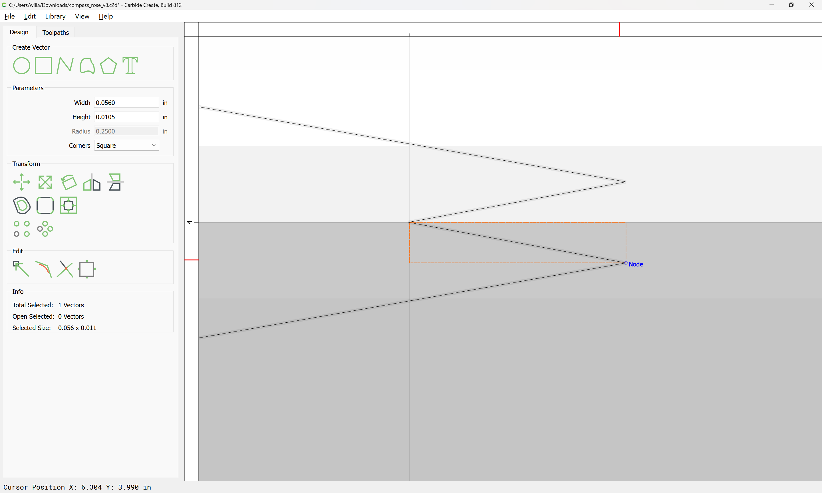
and then draw in a rectangle for the marks along the circumference:
and use Circular Array to duplicate it:
OK
Then add the circles which the rectangles interact with to the selection:
and use Trim Vectors to remove what is not wanted:


Continuing around until everything is removed…
Which may then be joined together:
Lastly we draw in the indicators for the four quarters by selecting the central portion of the design:
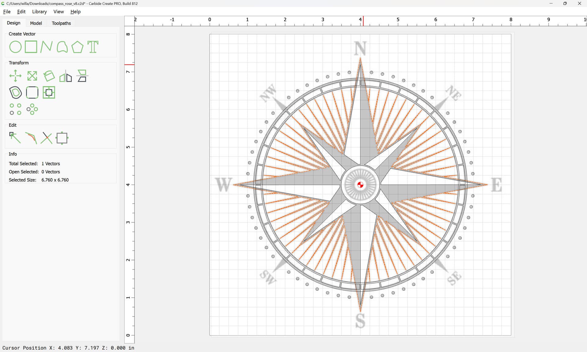
duplicating it:
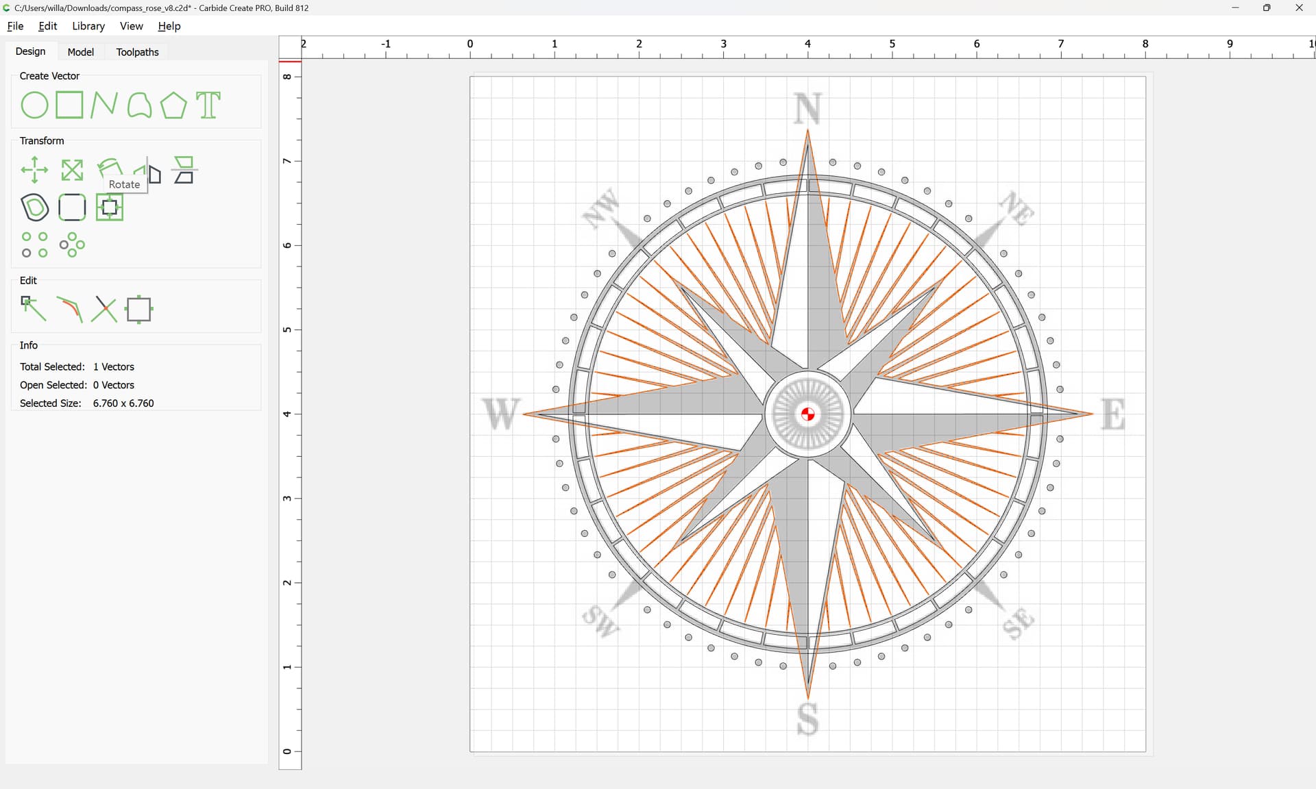
and rotating the duplicate 45 degrees:
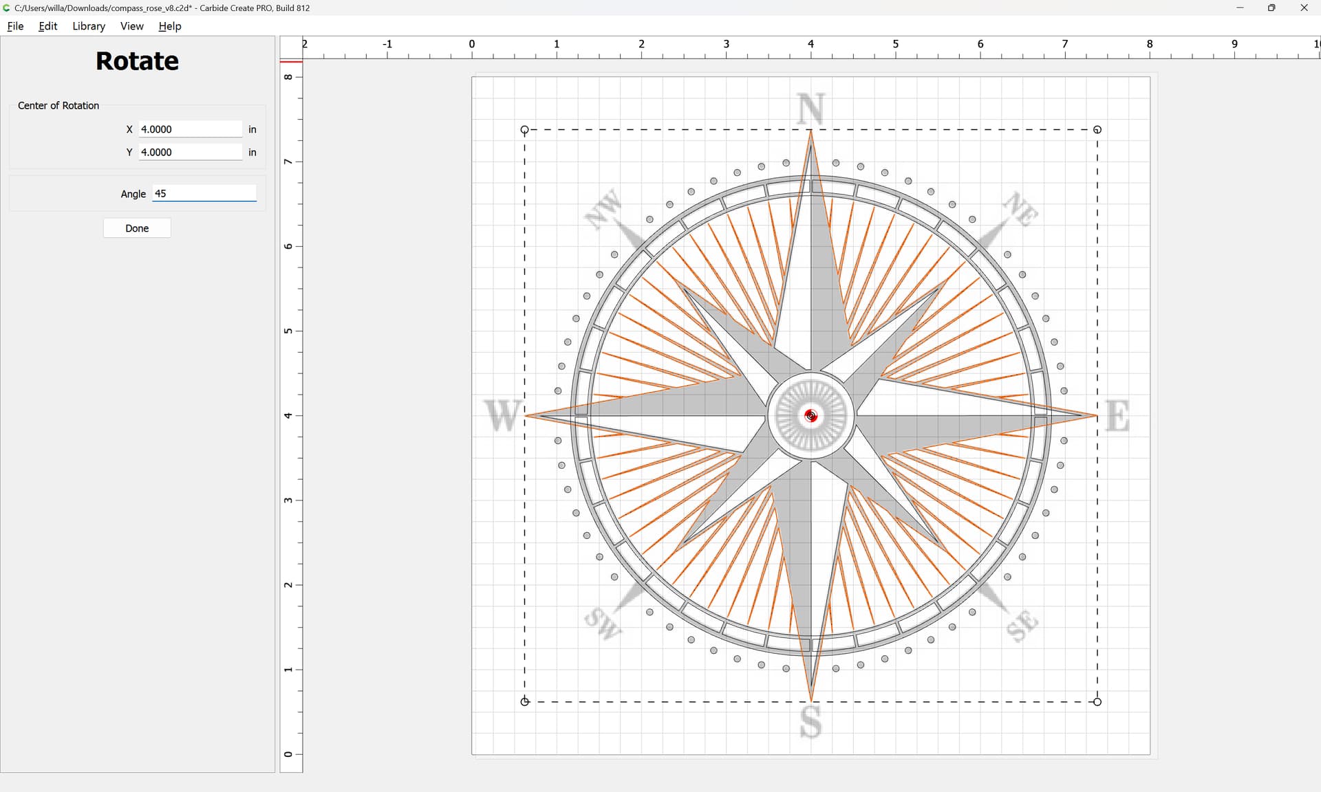
and then scaling it down slightly:

iterating until:
Select the overlapping geometry:
and use Trim Vectors and Join Vectors as before to remove what is not wanted and close the finished geometry.
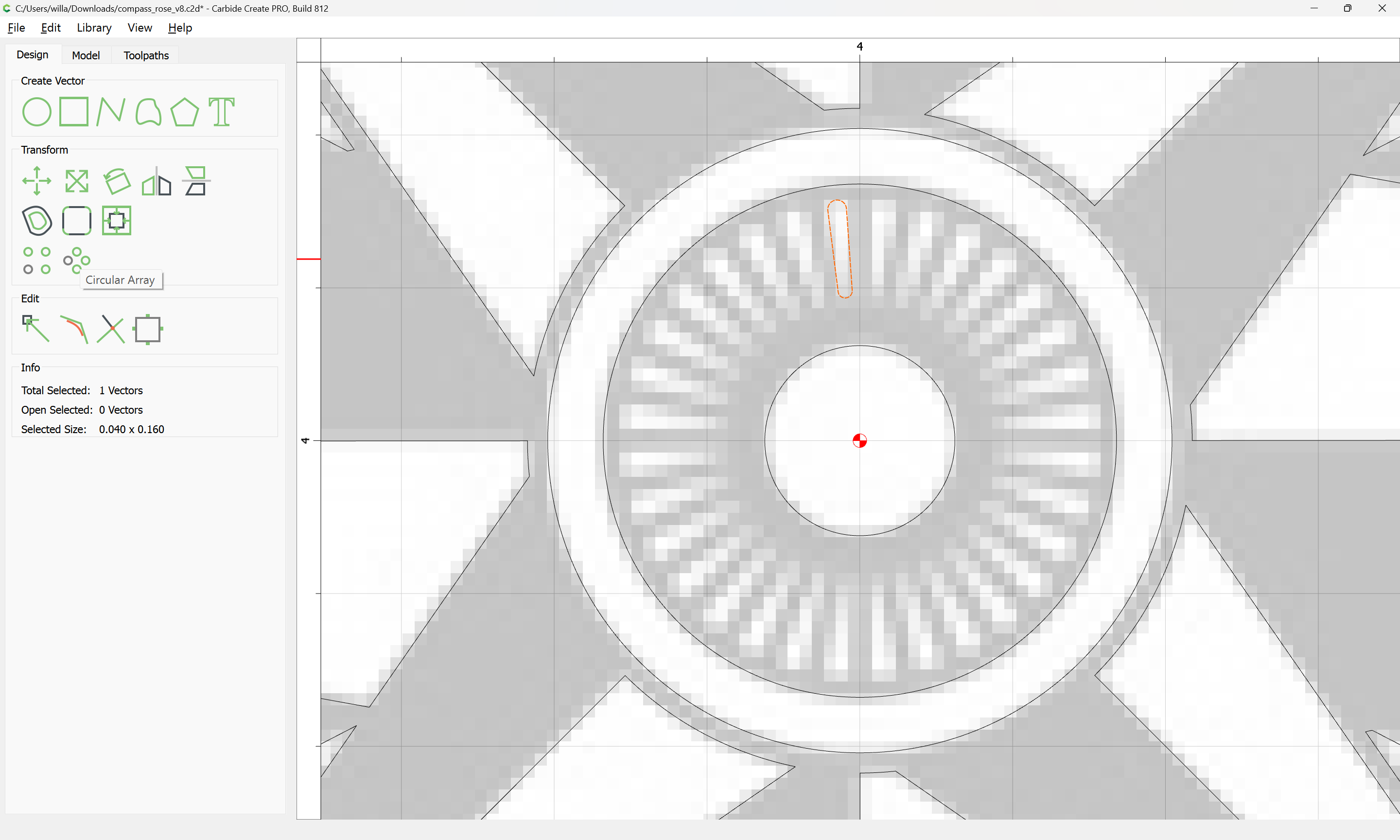
Then draw in the elements of the interior rosette:
There are 32 highlights, which I believe would best be represented as a pair of hulled circles:
Rotate these into position vertically so as to facilitate working with them:
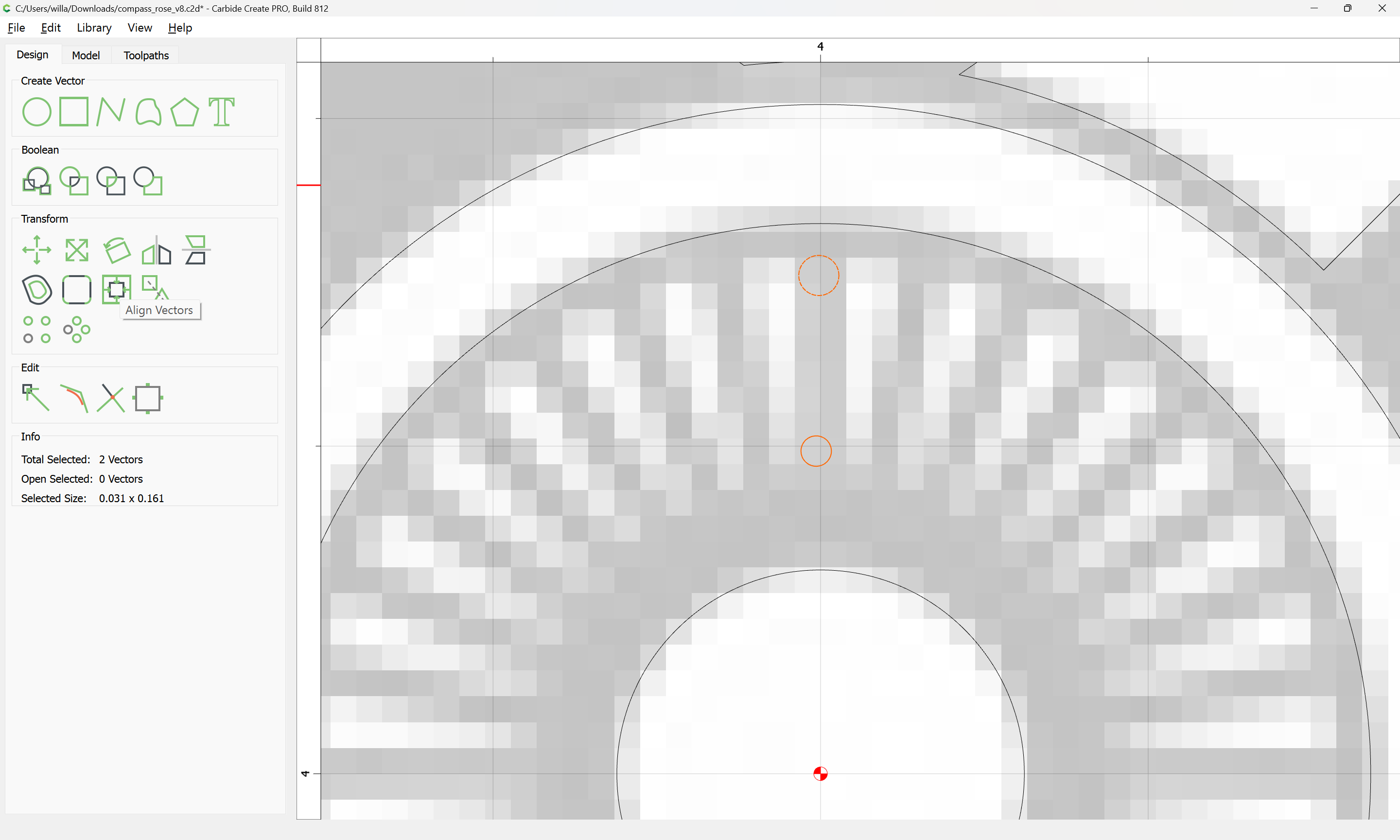
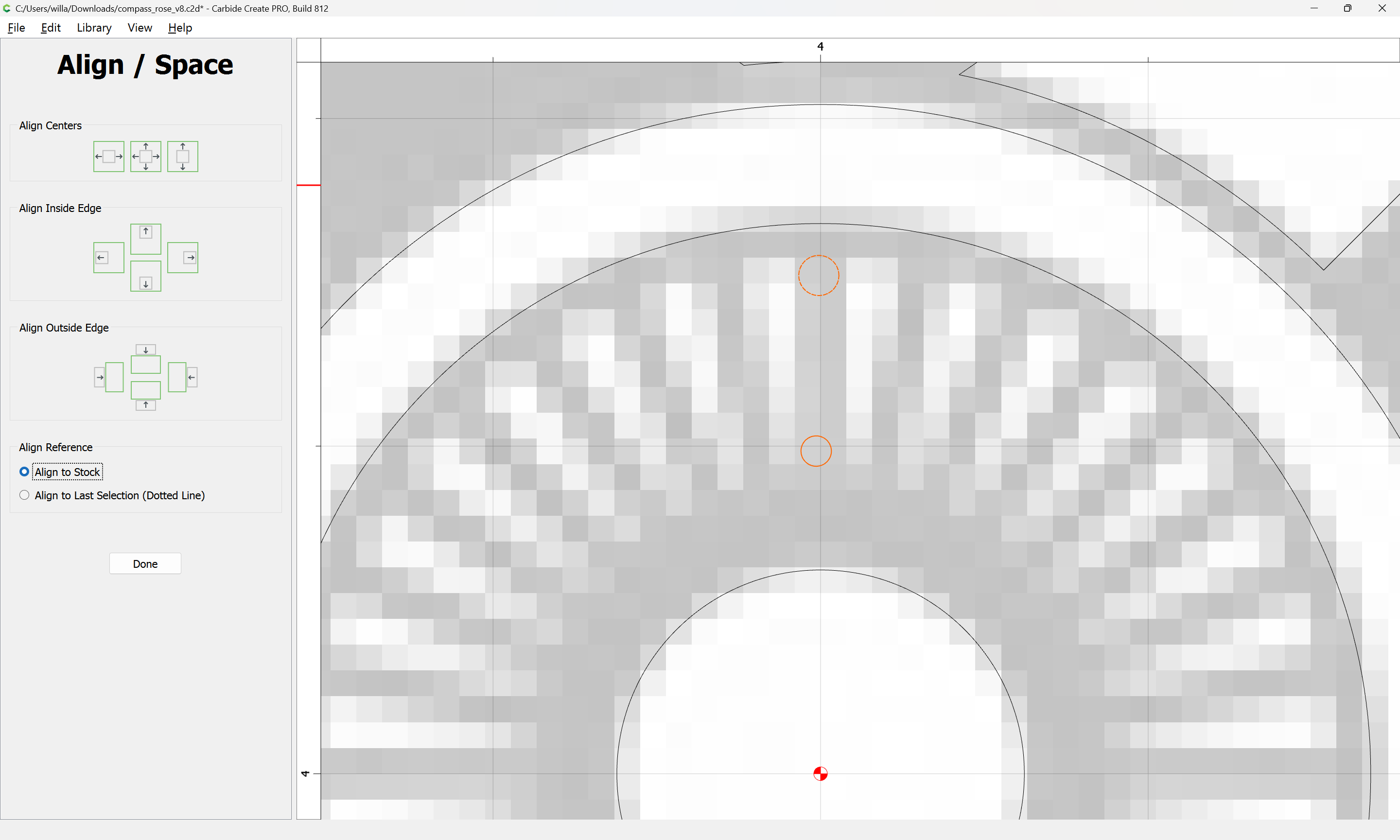
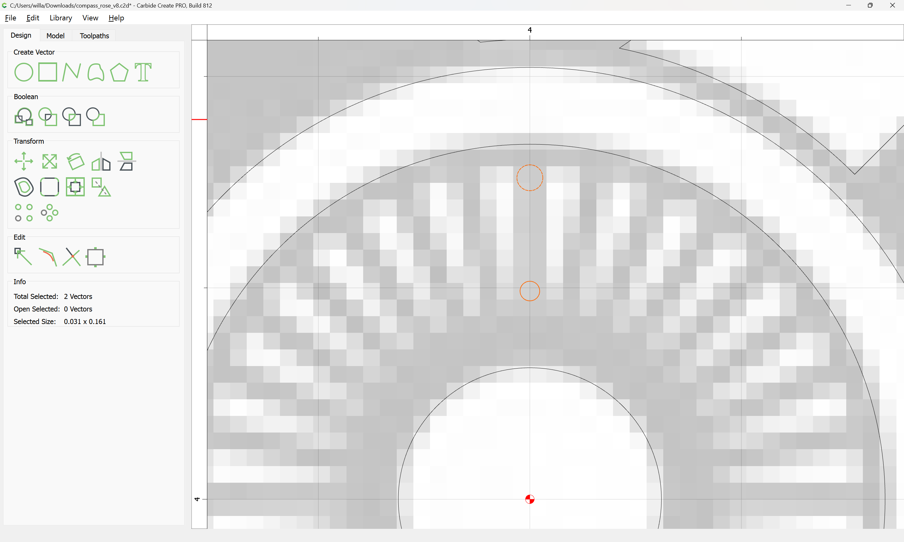
Then center them to the Stock:
Then draw in a line to connect the two circles along a tangent:
Zooming in and adjusting using Node Editing until things align reasonably well:
Select the elements and duplicate and mirror:
(being careful to maintain alignment)
Draw rectangles which define the points of tangency:
Select the elements for this:
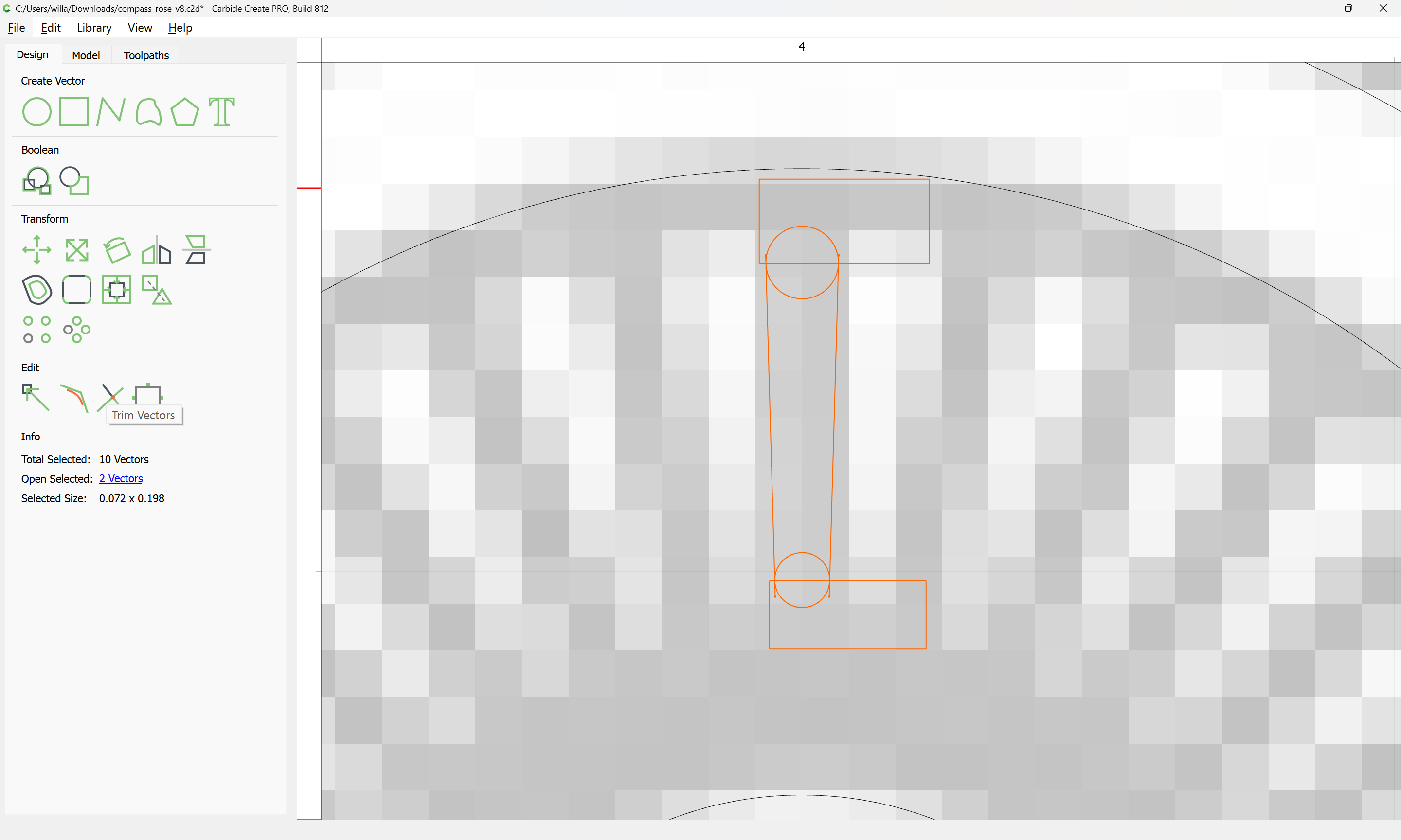
and use Trim Vectors:
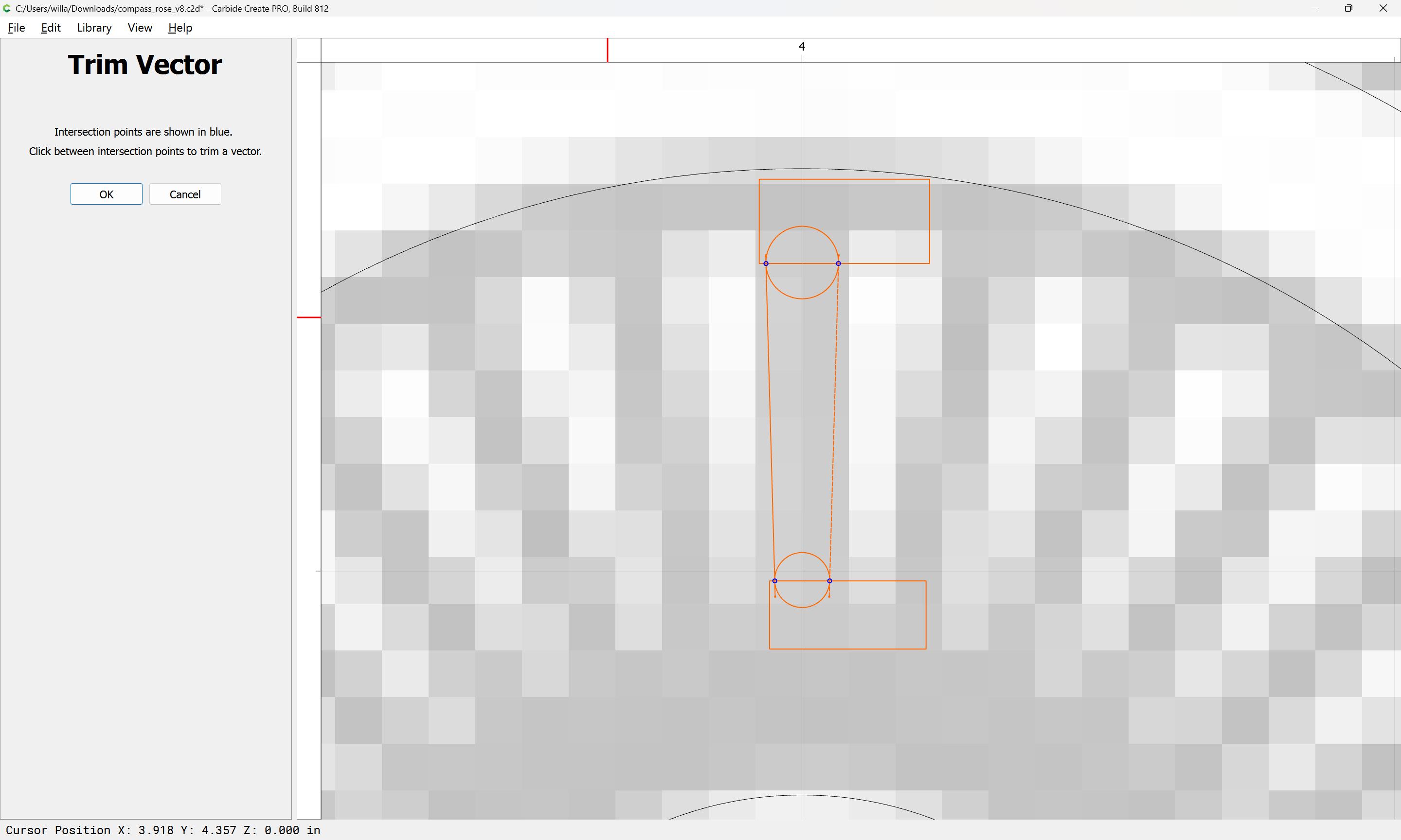
to remove what is not wanted:
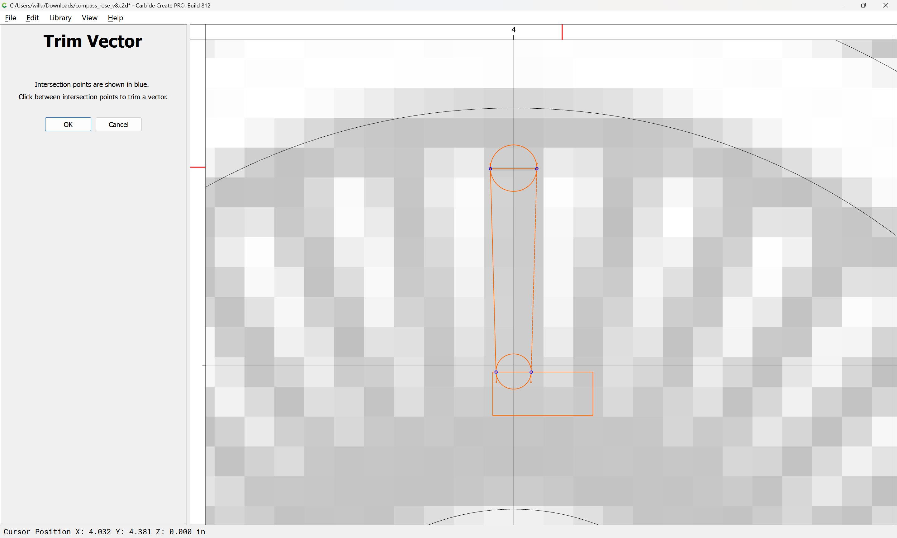
until one arrives at:
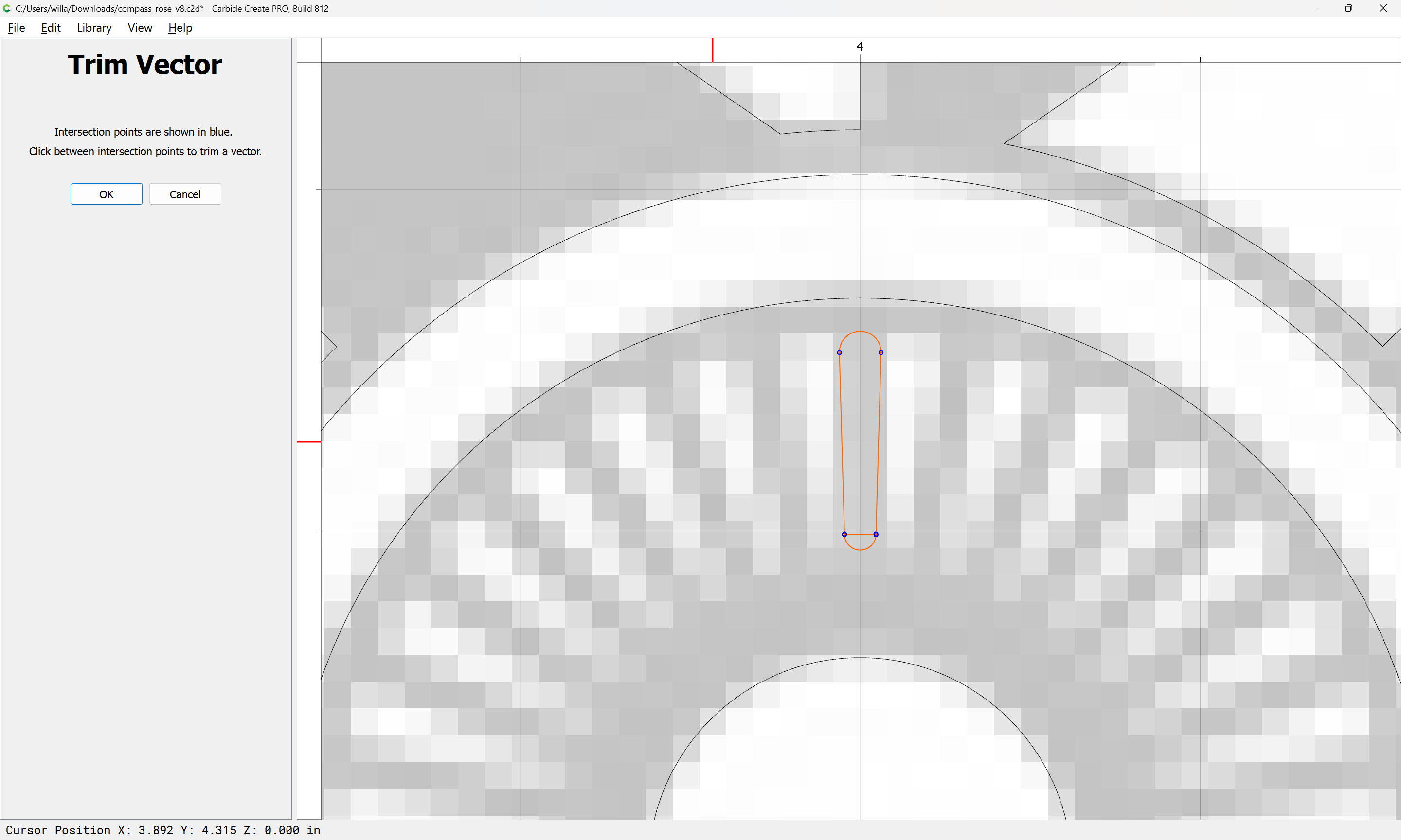
Delete the unwanted bar:
Then select and Join Vectors:

Rotate the design element into alignment:
Done
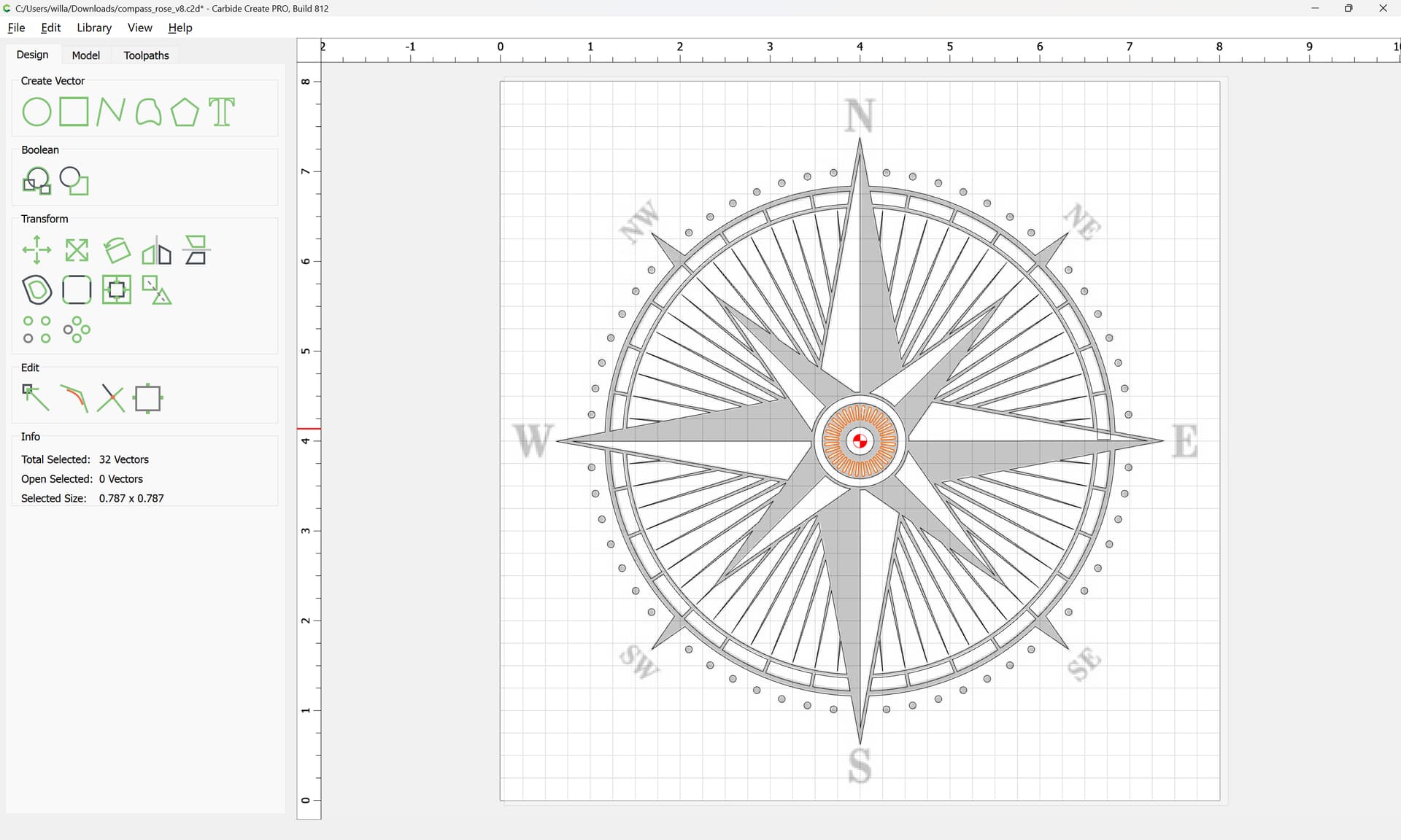
Then use Circular Array to finish the rosette:
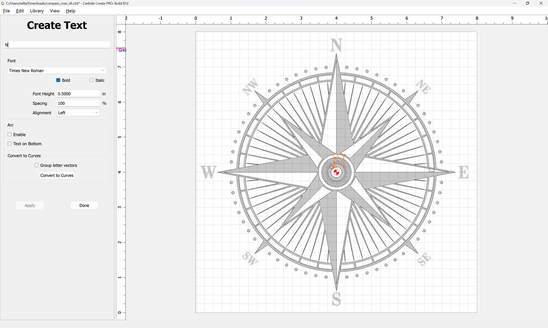
Lastly set the text.
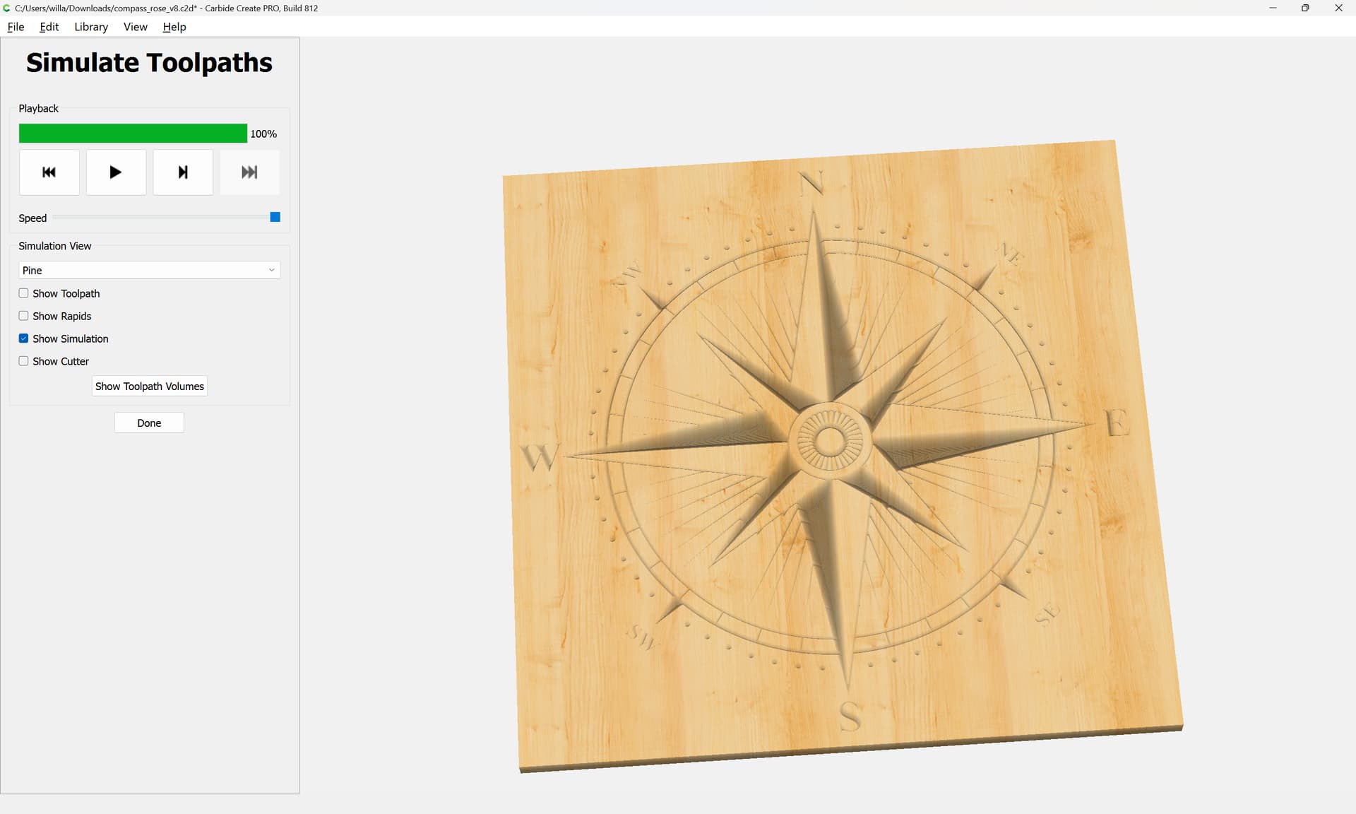
3 Likes
This topic was automatically closed 30 days after the last reply. New replies are no longer allowed.