I made the move to a spindle after I found a great package on Amazon for $300:
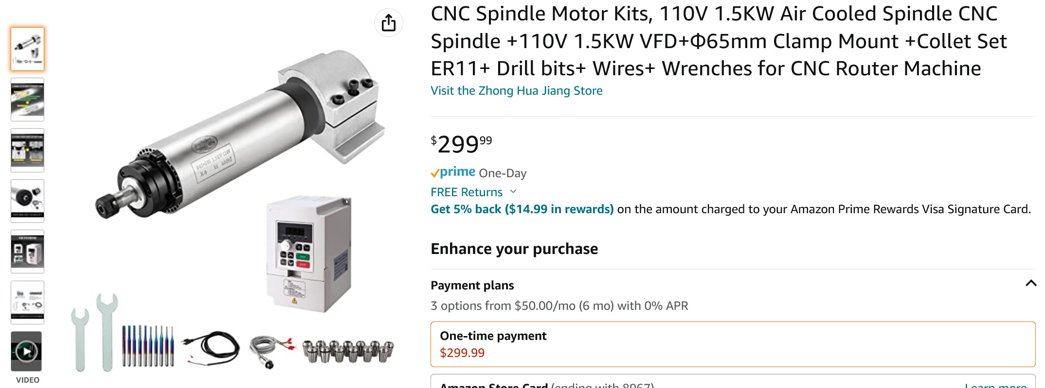
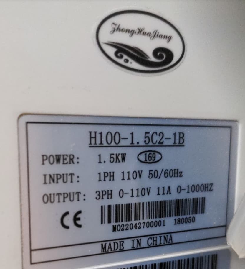
The manufacturer is the Changzhou Huajiang Electric Appliance company, Zhong Hua Jiang branded on the sticker and brochure. The VFD is branded the same, model H100-1.5C2-1B.
There are plenty of posts documenting portions of the setup, but not many for this particular model of VFD, and not complete. I’m documenting my full setup, which is working perfectly, and some considerations and things I tried so you don’t have to, or at least know what my outcome was. I think a lot of the “coding” in the VFD is the same from model to model, so this may apply to other models. The H100 is the “compact” model, and the terminal block may be labeled differently on other models.
First - why this model? I had a few considerations.
- I did not want to run another 220V drop, so I focused on 110V.
- Watching some comparison videos, the sound difference in a water-cooled vs. air-cooled was nominal, so I decided not to mess with a water pump setup, just another complication.
- I’m on a 2020 Shapeoko 3 XXL - great machine but it did not make sense to upsize to a 2.2KW setup. I’m sure it can handle it, but really overkill for what this gen of machine is made for. The newer machines with rails and ballscrew drive could get more out of a larger spindle.
Ultimately, which cnc you have doesn’t matter much, because this is focused on setting up the VFD to work with the grbl board. My VFD and spindle worked out of the box, wired right up according to the instructions and I was able to operate in manual mode using run/stop and the potentiometer.
To get the full value and safest operation, you’ll want to pick up a 5V opto-coupler relay. It was $8 for 4 on Amazon. More on this below the table.
VFD Settings
First up, let’s get to the VFD settings I modified with notes about each command and why I changed it.
| Menu | Description | Factory (According to book) | As Delivered | Modified to | Notes |
|---|---|---|---|---|---|
| F001 | Control Mode | 0: Keyboard | 1: External Terminal | Sets the run command to be from signal to terminal block. This allows you to control the VFD from commands sent in the gcode through your grbl board. | |
| F002 | Frequency Setting Selection | 0: Operate Potentiometer | 1: AI1 | Tells it to look at AI1 for the PWM voltage to set the speed. | |
| F023 | Reverse prohibit | 1: Reverse allow | 0: Reverse prohibited | Prevents accidentally sending the spindle in the wrong direction | |
| F040 | F/R Key Function | 0: F/R | 1: Control Channel mandatory for keyboard | This allows you to switch to the keypad control by holding down teh F/R button, otherwise you are locked out of keyboard for Run/Stop/Speed. Not strictly necessary, but a good backup to go into override mode and use manual controls. | |
| F044 | X1 Function | 2: Forward | 1: Run | Using Run allows a Start/Stop signal to be used to fully stop power to inverter output. Wiring this with an opto-sensor from D13 on grbl board (note: must enable D13 output, see below) allows a dedicated Run/Stop command. I think this one is critical, lots of posts just jumping X1 to ground. That puts it in a permanent “Run” state (with 2: Forward or 1: Run). Using 1: Run and a putting an opto-coupler on will enter into a safer “Stop” mode with the M05 command vs. “Run” mode with 0 RPM. | |
| F045 | X2 Function | 3: Reverse | 13: Emergency Stop | Maintains current settings, but enters fast deceleration to stop. Wire this to a NO switch or e-stop. | |
| F046 | X3 Function | 14: Reset | 14: Reset | Reset if error. Wire this to a momentary push button. | |
| F070 | Input Channel Selection for Analog Qty | 00 | 01: AI1 0-5V | Sets to expected PWM voltage output from grbl board | |
| F072 | AI1 Channel Gain | 100 | 96.5 | Adjustment made based on readings from spindle speed and laser tachometer | |
| F170 | Selection of extension display 1 | 4: Bus voltage | 2: Operation Speed | Adds the RPM in the display sequence when pressing Double Left Arrow | |
| F171 | Selection of extension display 2 | 5: Heat sink temperature | 3: AI1 | Adds PWM % to the display sequence (input voltage/5V) | |
| F184 | RPM Display factor | 1 | 0.1 | For 4 digit screen, drops the last digit. 8000 RPM reads as 800, 12000 RPM reads as 1200. | |
| F185 | Startup preset display selection | 0: output frequency | 4: Designated by F170 | Set RPM to be the main display when you power on if you set that in F170 | |
| F193 | Output open-phase protection | 1: Invert output prohibited when the load is out of phase | 0: Inverter output allowed when the load is out of phase | * | * Should probably be 0, but have not changed yet |
| F194 | 0Hz output enbale | 1: Inverter output prohibited at 0Hz | 0: Inverter output allowed at 0Hz | 1: Inverter output prohibited at 0Hz | Not sure why this shipped with it “allowed”, seems safer to have this set to prohibited |
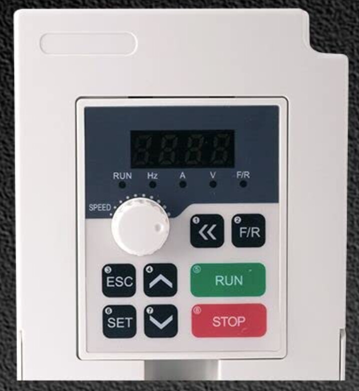
Navigate the “keyboard”
A couple notes on menu navigation with this helpfully numbered image (note: my actual buttons are not numbered)
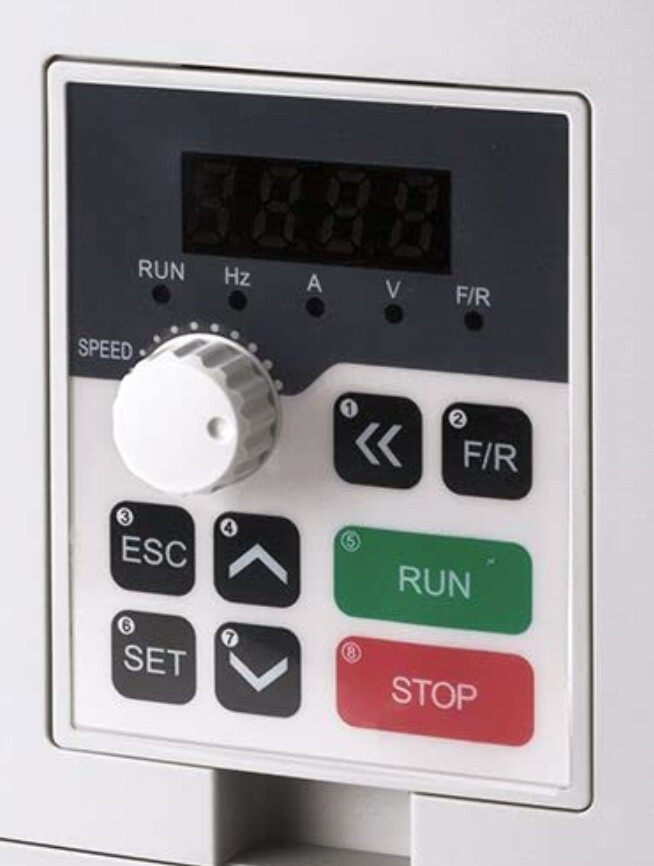
To enter the menu to change items press 6 “Set”. Use 4 Up and 7 Down to navigate one at a time. To quickly go to a item, use 1 Double Left Arrow to go to each digit in F— and use 4 Up and 7 Down to change. Press 6 Set to see the set value, then 4 Up and 7 Down to modify. 6 Set again to save or 3 Esc to leave without changing.
A quick way to go through all your settings, keep pressing the 6 Set button. It will auto advance through the full menu and show you the settings as you go.
Check your grbl board
There are 4 pins we need, PWM, D13, 5V, Ground. There are several posts on finding these. I did a write up here Router on/off and speed control with SuperPID and cncjs for SuperPID which applies to this as well. You can get to this pin out at a couple different headers depending on your board.
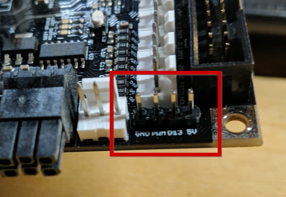
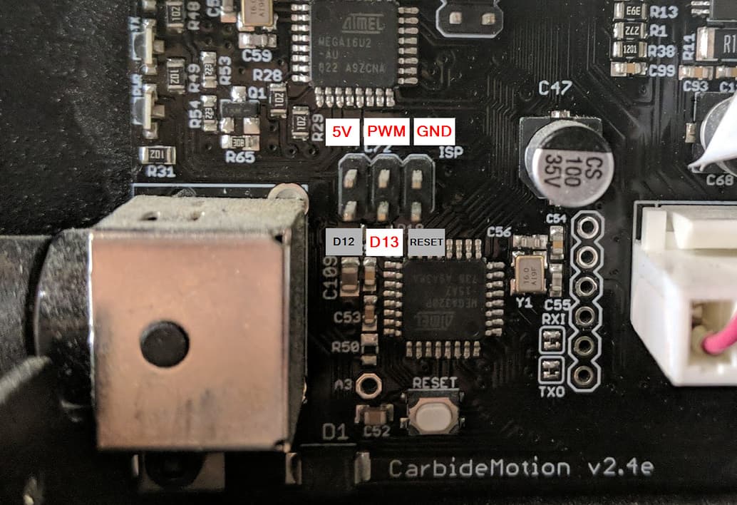
You do need to modify your board settings as noted in the above post to switch D13 from “spindle direction” to “enable” (not terribly complicated, full instructions in post).
Router on/off and speed control with SuperPID and cncjs:
Note: I’m not sure what the output is from D13 normally without this change because I don’t feel like flashing my board back :-). You can test with your multimeter. My understanding is M03 (Spindle CW) makes no change to D13. M04 (Spindle CCW) turns this “on”, but I’m not sure if this state change makes it a 5V pin, which is what is needed. You may be able to figure out a way to make this work, something messy like updating all your gcode to use M04 instead of M03, but still not sure when it changes state (does it revert when the M05 command is issued or stay in the “on” state until an M03 command changes it?). Ultimately probably better and safer to flash the board and make D13 a true “enable” pin.
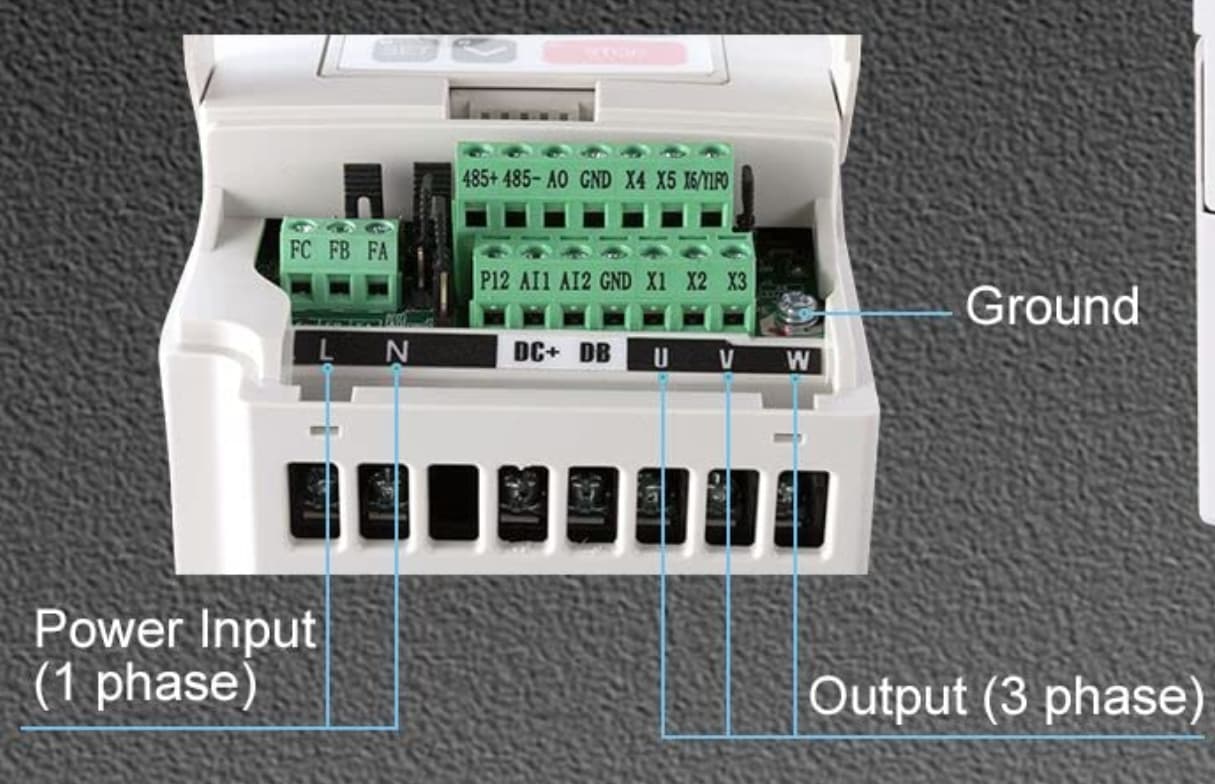
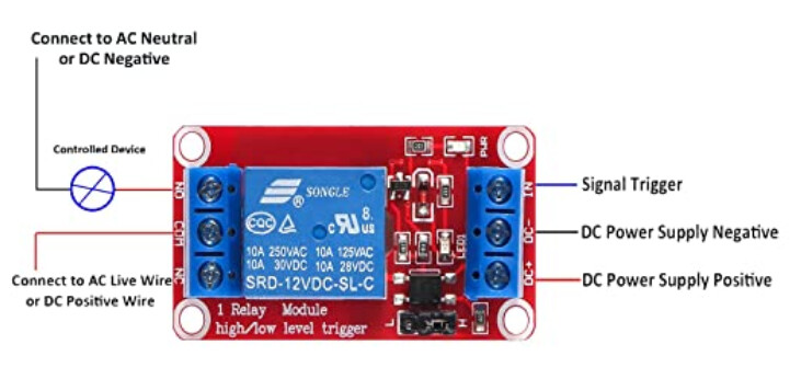
Wire in the opto-coupler
We’re using an opto-coupler because we’ve set X1 to be the “Run” command. X1 is Normally Open (NO) and therefor in a “Stop” state. Using the relay we’ll close this circuit and enable the “Run” state.
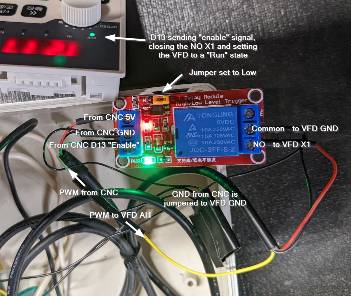
There’s a lot going on in that picture, so let’s break it down.
- The opto-coupler is a 5V powered relay. You’re pulling from a constant on 5V source on your grbl board to give the relay power to DC+.
- You need a ground as well, pull this from your grbl board and attach to DC-.
- Attaching to D13 to IN signal trigger (next to DC-), this tells the relay to open or close base on the state change.
- Set the jumper based on how your D13 output works. My D13 has a reading of 5V when the spindle command is off (M05) and nothing when it is on (M03) because I have “INVERT_SPINDLE_ENABLE_PIN” enabled. I set my jumper to Low (L) to trigger the circuit to close. If your reading is nothing with the spindle command off (M05) and 5V with the command on (M03), then select High (H).
- Mine if M03 then D13 = no output; if M05 then D13 = 5V
- Could be reversed depending on your config.h update, set jumper accordingly
- On the other side, connect VFD GND to Cmn.
- Jumper your CNC GND to the VFD GND - this is important, your PWM will not function correctly if it does not ground back to the CNC board. (note: I created a ground block that connects all my switches to 1 wire, elegantly wrapped in electrical tape in the photo. This way I only had to bring 1 ground wire into the VFD.)
- Connect the NO (Normally Open) to VFD X1.
- Connect PWM from CNC directly to AI1 on the VFD.
If you send a M03S3000 command, your CNC will change the “enable” state on D13, closing the relay circuit causing X1 to ground the VFD to go into the “Run” state. Sending M05 will change the D13 state again, opening the circuit and disconnecting X1 causing the VFD to go into the “Stop” state.
That’s a lot to do when you could just wire X1 to GND permanently and control only with PWM wired to AI1. The spindle stops when you issue the M05 command because RPMs go to “0”. Seems to work, right?
What I don’t like about that is the spindle remains in the “Run” state. I tested on mine and the green “Run” light remained on. While unlikely for anything to happen, just doesn’t seem very safe. I prefer to have 2 signals telling the VFD to be off - the disabled X1 and the PWM 0 on AI1. You go with what makes you comfortable.
Note: I tested wiring the PWM to the IN signal trigger on the opto-coupler. Unfortunately, it did not work, the IN trigger needs a 5V signal to work.
Note: I considered switching the NPN jumper to PNP. This changes X1 from a 12V output to an input to receive a signal. Unfortunately, it needs a 12V - 24V input to trigger, so this will not work from a feed from the grbl board with 5V outputs. Also a plus that the opto-coupler is isolating the voltage from the VFD and grbl board. (Although you do still have your PWM plugged directly to the VFD and your ground must be tied together as a common ground).
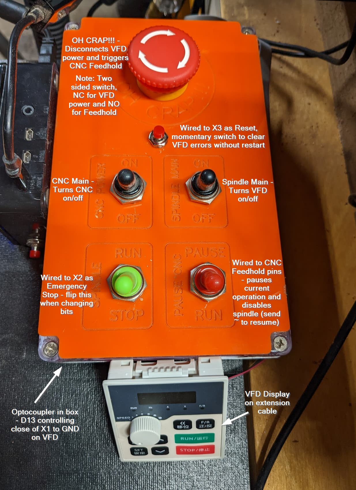
Other safety features to add
- If you decide to forgo the above optocoupler, at least bring a switch up from X1 to your work area. Flip the switch when you’re changing bits.
- I set X2 in the parameters to be “13: Emergency Stop”. Closing X2 to GND will put the VFD into a fast stop state disabling the spindle. I pulled a wire from X2 to GND up to a switch on my panel. I flip this when changing bits as a third layer of safety.
- X3 was already set to “Reset”. I haven’t had an issue yet, but some videos noted needing to momentarily close that to GND to clear errors. I pulled a button up for that as well.
What this looks like implemented
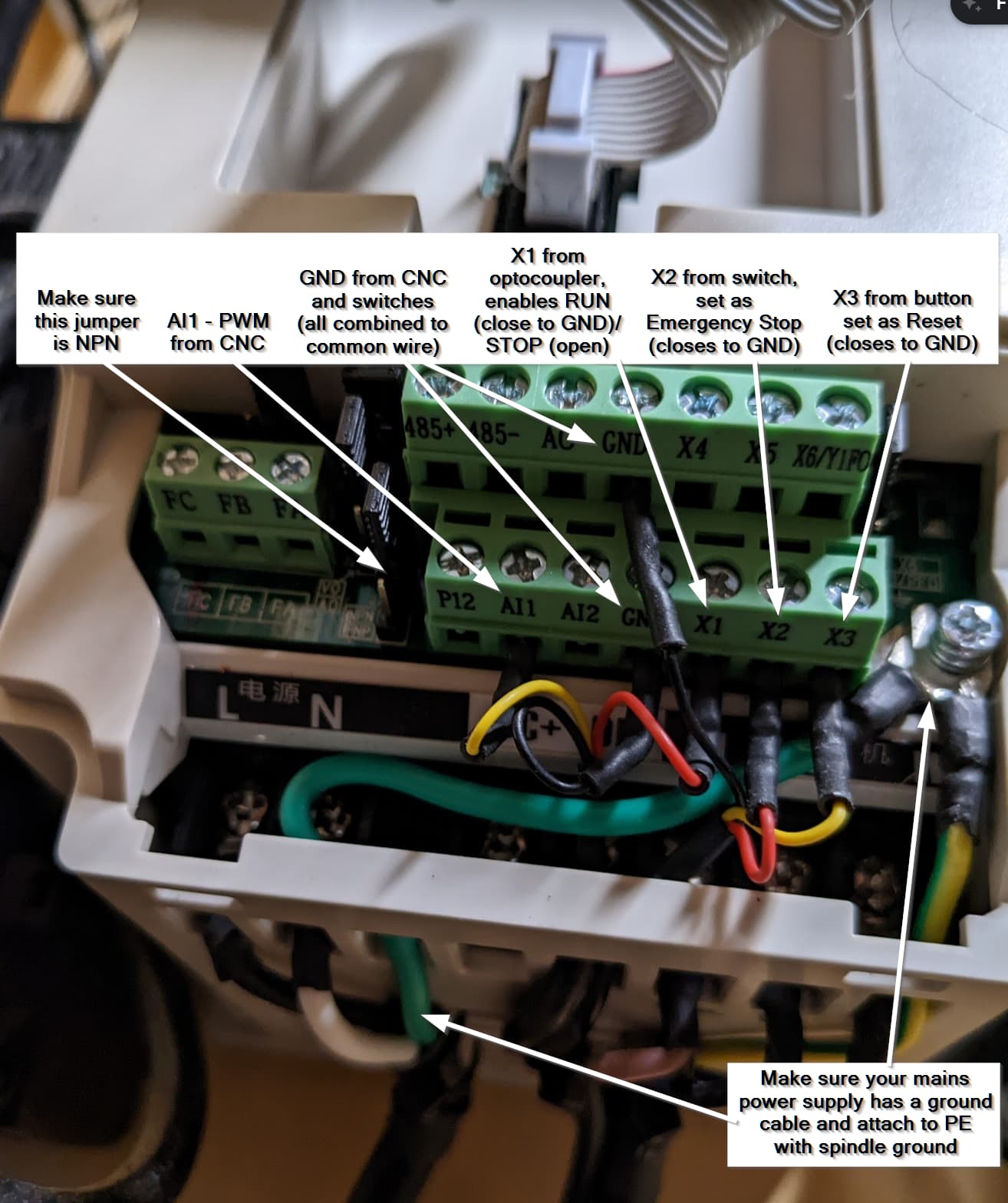
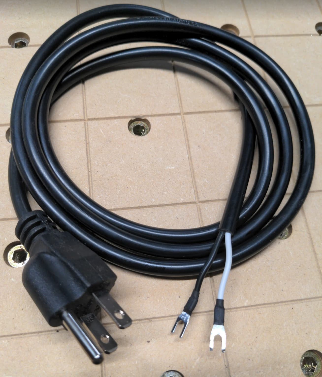
Check your electrical ![]() my VFD came with this 3 prong plug attached to a 2 wire cable. Put that in the trash and spend $10 on a proper 3 wire whip. If you don’t, your spindle ground has nowhere to go!
my VFD came with this 3 prong plug attached to a 2 wire cable. Put that in the trash and spend $10 on a proper 3 wire whip. If you don’t, your spindle ground has nowhere to go!
Software settings
Update your min/max spindle speeds.
$30=24000
$31=0
note: I used F072 to adjust the AI1 channel gain to 96.5%. This aligned my spindle speed with the desired set speed. Before, set to S10000 the VFD would read 10350 and S20000 read about 20700, confirmed with a laser tach, both about 3.5% high. Changing F072 put all speeds in line with expectations. You’ll need to verify and calculate your own gain.
The spindle takes a moment longer to ramp up to speed compared to the Dewalt. I was using a 3 second pause after the M03S---- command, updated this to 6 seconds.
M03S----
G04 P6
Make sure that gets added after every tool change and spindle start.
Manual control
If you set F040 to “1: Control Channel mandatory for keyboard”, then you can switch back to manual spindle control by holding down the F/R button for a moment. The light will begin to flash and you can control with the Run/Stop/Potentiometer dial. Hold again to revert to default computer controlled.
Break in and warmup routine
There’s some confusion on the break-in and warmup routines. From the manual:
- Break in the spindle prior to very first use by running
- 30 min at “low speed” (I did 500 RPM)
- 20 min at 3000 RPM
- 20 min at 6000 RPM
- repeat for 20 min ever 3000 RPM increment to 24000
- Ongoing, warm up the spindle for “15-20 min” each day before use. I’d also do this if I let is sit idle for multiple hours, especially when my garage is cold in the winter. I created a 15 min macro in cncjs to run while I’m setting up other things to prepare for jobs.
M3S500
G4P90.0
M3S1000
G4P90.0
M3S4000
G4P90.0
M3S7000
G4P90.0
M3S10000
G4P90.0
M3S13000
G4P90.0
M3S16000
G4P90.0
M3S19000
G4P90.0
M3S22000
G4P90.0
M3S24000
G4P90.0
M05
Other settings
These are what differed from “factory settings” in the book and how the VFD was actually configured. Nothing to change here, but good reference for checking. The instruction noted the VFD was pre-programmed to work with the spindle that came with it, so makes sense there would be differences. I captured all of these in case some situation wipes all the settings back to true factory, I wanted a record of it.
Note: this will be very dependent on the VFD and spindle setup you have, recommend going through and capturing yourself. I only noted values that were different than what was noted in the book.
| Menu | Description | Factory (According to book) | As Delivered | Modified to | Notes |
|---|---|---|---|---|---|
| F003 | Main Frequency | * | 400 | ||
| F004 | Reference Frequency | 50 | 400 | ||
| F005 | Minimum Operating Frequency | 50 | 400 | ||
| F006 | Intermediate Frequency | 5 | 10 | ||
| F008 | Maximum Voltage | 220/380 | 380 | ||
| F009 | Intermediate Voltage 1 | 11.5 | 14 | ||
| F010 | Low frequency torque boost voltage | 3 | 5 | ||
| F014 | Acceleration Time I | * | 10 | ||
| F015 | Deceleration Time I | * | 10 | ||
| F016 | Acceleration Time II | * | 5 | ||
| F017 | Deceleration Time II | * | 5 | ||
| F018 | Acceleration Time III | * | 5 | ||
| F019 | Deceleration Time III | * | 5 | ||
| F020 | Acceleration Time IV | * | 5 | ||
| F021 | Deceleration Time IV | * | 5 | ||
| F028 | Stop Frequency | 0.5 | 0 | ||
| F031 | DC Braking Level | 2 | 30 | ||
| F041 | Carrier Frequency | * | 5 | ||
| F063 | Timer 1 | 0.1 | 1 | ||
| F064 | Monostable pulse width setting | 0.1 | 5 | ||
| F065 | Counter reference value | 1 | 0 | ||
| F118 | Stalling Level during accelleration | 150 | 155 | ||
| F122 | Prevent of over-voltage stalling level | model dependent | 370 | ||
| F123 | Selection of over torque detection mode | 0 | 1 | ||
| F128 | Cooling fan control | 0: running always | 1: control by running command | ||
| F129 | Dynamic running voltage | model dependent | 360 | ||
| F140 | Rated power of motor | * | 1.5 | ||
| F141 | Rated voltage of motor | * | 110 | ||
| F142 | Rated current of motor | * | 7 | ||
| F143 | Number of motor poles | 4 | 2 | ||
| F144 | Rated rotating speed of motor | 1400 | 2400 | * | displays as 24.00 |
| F148 | Motor slip compensation maximum frequency | 2 | 4 | ||
| F149 | Motor slip compensation filtering time | 10 | 100 | ||
| F150 | AVR function | 1 | 2 | ||
| F155 | Time of fault restart | 99 | 0 | ||
| F156 | Proportional constant P | 100 | 10 | ||
| F159 | target value | 0 | 50 | ||
| F191 | Magnetic flux brake strength | 120 | 115 | ||
| F193 | Output open-phase protection | 1: Invert output prohibited when the load is out of phase | 0: Inverter output allowed when the load is out of phase | * | * Should probably be 0, but have not changed yet |
| F194 | 0Hz output enbale | 1: Inverter output prohibited at 0Hz | 0: Inverter output allowed at 0Hz | 1: Inverter output prohibited at 0Hz | Not sure why this shipped with it “allowed”, seems safer to have this set to prohibited |
| F196 | Acceleration and deceleration time of VF seperation voltage | 30 | 300 | * This one may be 30.0 and missing decimal on screen, range was 0-100 |
A note on the manual
The manual for this was pretty darn good and well thought out! The front section was a straight list of functions and option values, the back section was detailed descriptions with use case examples. It included a description and diagram of using the opto-coupler to control Run/Stop on X1. I’ve emailed to see if they can send a PDF, I can’t find one online.
Support responded in a couple hours with the manual! Version 1.8 09/10/2021: new H100 manual V1.8.pdf (1.6 MB)
^^^^This version is what’s referenced above. There are some differences! F040 controls the “F/R button” in v1.8 and “frequency resolution” in v1.0. Make sure you reference the correct manual for your VFD as there can clearly be differences. My VFD software version (F181) is 1.73.
Leaving this older version here for reference. Older version 1.0 01/10/2019:VFD_manual_H100_manual_V1.0(20180525).pdf (3.4 MB)
Full function list in xlsx with notes from above tables. Also added tab and column for v1.0 for easy comparison: H100 V1.8 Function List.xlsx.zip (44.2 KB)
English website: https://www.zhonghuajiangspindle.com/
There’s probably some additional interesting things you could do, like use a setting to power on vacuum when the spindle is enabled. Need to dig deeper on some of those options.
On Z-Axis hardware
I did upgrade from Z-Plus to the HDZ and got the upgraded 65mm spindle mount to go along with it. Well worth the investment for the quality of both. The Z-Plus handled the trim router just fine, but the weight of even this smaller spindle would be too much over time.
And finally
I selfishly like documenting these things here for my own recollection of how the hell I made something work or why I made a particular decision on a setting. It’s easy when it’s fresh, but now it should just run and I’ll forget how the sausage was made. I hope someone else finds this useful too! ![]()