How to install E stop

This is exactly what I’m trying to do, however on my board (2.4C) there is no EStop pins. I have XYZ limits switches, then Probe, then Feed Hold, looks like my revision of the board omits the EStop pins, at least in the location where they are normally found. I have the stop button, similar to above with two poles, one NO one NC, but nowhere that I can find on the board to connect the NO side. That’s where I get stuck, it appears the board has changed a bit lately. Does anyone have this late model board (2.4C) and found where the EStop pins are now located, or can C3D confirm that they have been removed altogether?

@RichCournoyer: I’ve thought about running a relay to kill everything, but I don’t even want the 1/1,000,000 chance of a relay sticking or some other part of my Rube Goldberg contraption failing while the machine is chewing away at my chihuahua that somehow jumped up up on the bench and decided that licking the running spindle is a good idea;-)

Thanks for the help guys!

Dan

I recently installed (a few months ago) the 2.4 board and can confirm that there are fewer pins on this board, but I can’t recall which pin has been removed. I’ve searched for a GOOD photo on this board and there doesn’t seen to be one.

I will open my board cover in a few days (to install a GCode Spindle switch, but that’s on another discussion), and will photograph it.

Dan: I’d email support and see if they can tell you where the estop pins are. Surely they did not remote that feature?

I would think that feature, albeit unsupported would not have been removed, but I can’t find it anywhere on the board. Maybe it was re-implemented somewhere else on the board? I dunno? I emailed support, hopefully hear something soon. Thanks for the help, I’m sure I’ll get there one way or the other:-)

Dan

Sorry to hear there is no e-stop pins any longer. I really like mine. I hope support comes up with a work around in-case I ever have to change out my 2.3 board?!?!?! On my board it is clearly indicated as estop. I can tell you it does stop during any motion rapids or not, I have used it many times. It’s a great insurance button for me.

1 Like

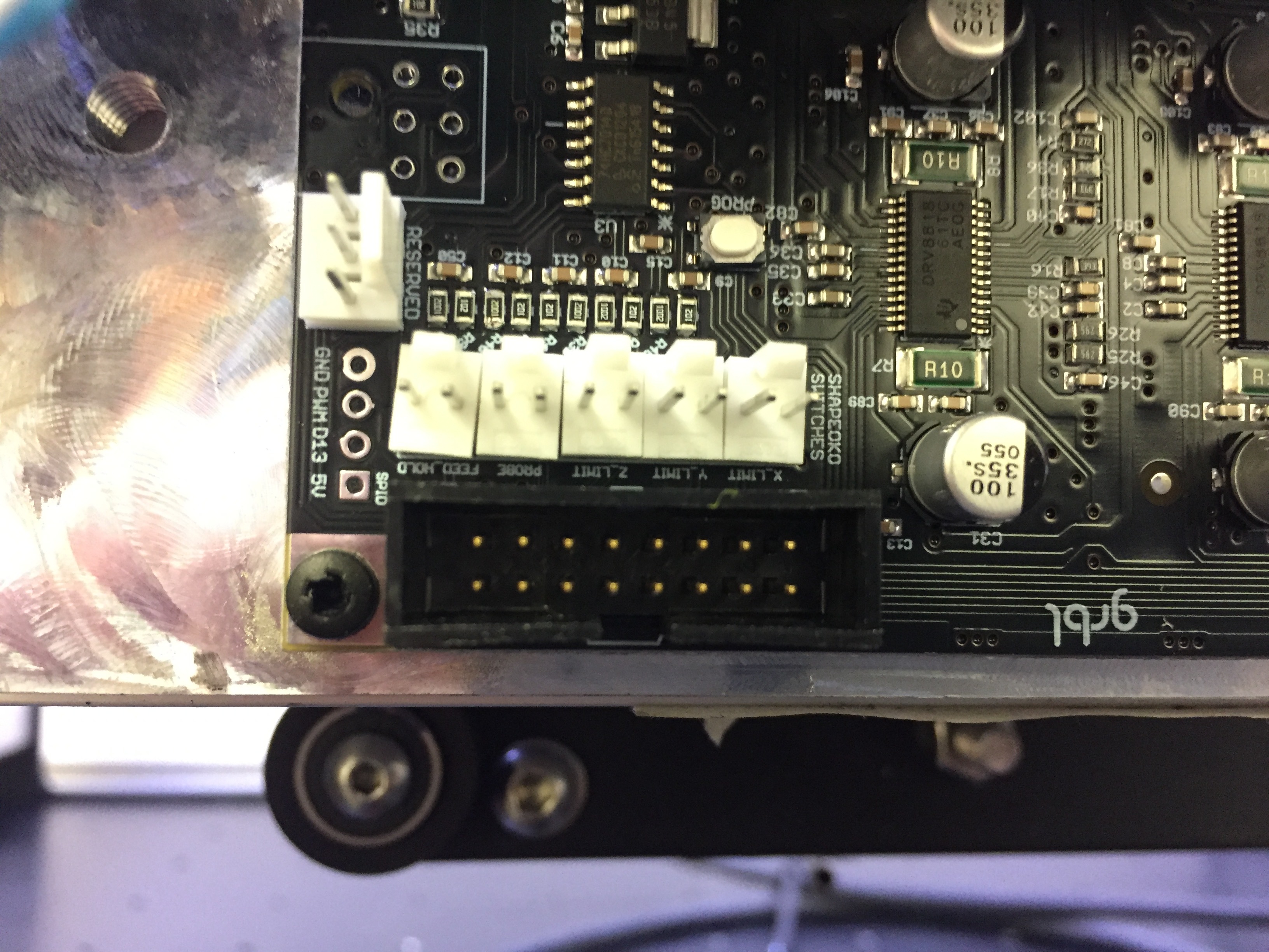
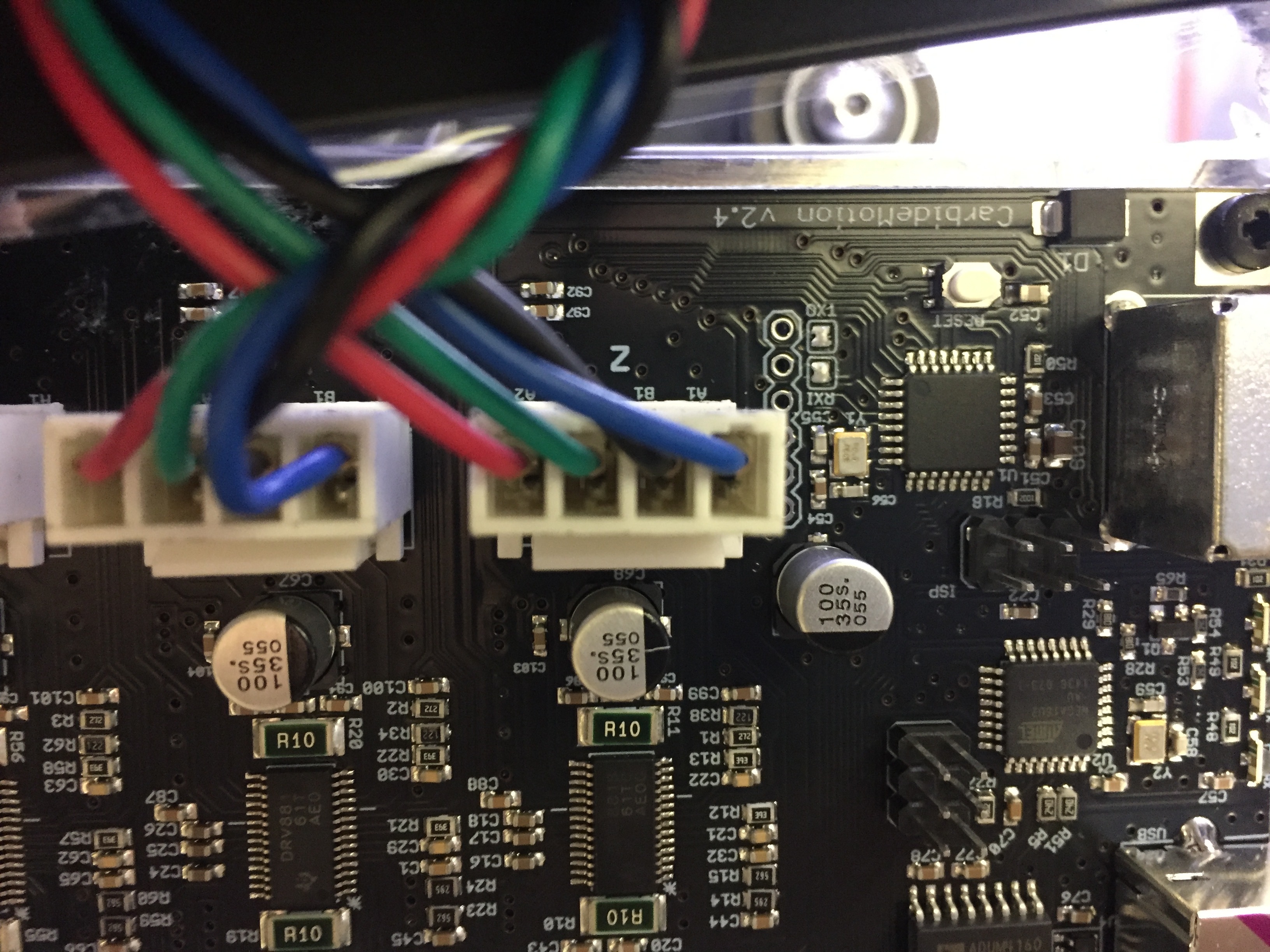
I got to look at my board today and V2.4(No Letter) has NO E-Stop pin. BUT I also see that the E-Stop button is no longer on the Nomad either, just a power switch. So you might want to go with my easy E-Stop method above.

Yea, I hadn’t revisited this topic, but I did receive a support email stating that the EStop pins had been removed. From my understanding this was never really a supported feature on the SO3, and the Nomad now uses a different method. A bit of a bummer, but I totally understand why this would be done since the machines share the same boards, and the machine that used those pins no longer uses them. I was also given some guidance on how to make this work with the current board, which is basically to cut power to everything. I picked up a relay and plan to go that route pretty soon, just have a few other projects in line ahead of it now(like capturing the raccoon family that has recently made my attic home…caught one already, live trap, pretty good deal for them, they get a free meal of canned cat food then released far away…I pay for dinner, short term housing and transportation!!!).

Thanks to everyone for all the help!

Dan

3 Likes

Please be very careful handling the critters, and clean up their droppings very carefully — they can have some nasty parasites/bacterial infections.

In case anyone wanted pictures of the 2.4D board I just received today. As stated no E-stop pins on this board either


1 Like

Can someone enlighten the community (OK, me) about the purpose of the IDC ribbon cable connection on the upper right of the v2.4d PCB (the last picture)?

Does this parallel the limits, probe pins?

1 Like

That’s to connect it to a nomad

1 Like

As the pics show… I have a Green side and an Orange side.

Several posts indicate that the Open Side goes to the E-Stop pins.

Ex:

My problem…
The only printing on my new E-Stop switch is in Chinese. :slight_smile: Can anyone tell me how I can tell which side of the switch is NO and which is NC???

And once I know which color side is Normally Open… do I connect the two wires to the same color terminals?

Thanks

My switch looks the same as yours. You can actually see the contacts inside open and close. Mine the green side is N.O. Yes connect to same color.

1 Like

A million thanks Steve.

1 Like

Probably best to ring it out with a multimeter to be sure, the one I have wasn’t real clear either. Also does your Carbide board have EStop pins? Mine is a later board and does not, so the best I could do was cut power.

Dan

Hey Dan,

Thanks for the note.

My board does have the pins. I bought the E-Stop and a Touch Plate at the same time and picked up the male & female connectors from DigiKey. I’m gonna give it a shot later this week.

Thanks again

Very happy with my new Shapeoko. I do question carbides are not incorporating/offer him a killswitch option. CNC machine even for the most experience machine can be dangerous.

1 Like

I’m happy with my shapeoko 3 xxl. Ive had it maybe a month or a little longer, I have serious catching up to do. I work nights and loads of hours so I don’t often have time for it but there’s so much to learn! My last project was a vinyl cutter which is still cool but way simpler that this bad boy. I gotta say though, my vinyl cutter program can do matrix copies which is multiple images but carbide create gets a headache and breaks a sweat when I do multiple copies say to rout the same image many times on a single workpiece… But all in all very happy I made the purchase!

Hi Rich. thanks for posting this description on wiring an Estop using a power strip and extension cord. I have a question: I see the Estops on amazon all showing both 1NC and 1NO. which do we want for your set up - NC? thus when the switch is hit, it opens the circuit? am I understanding this right? thanks

Search for “Router Power Switch” on Amazon.