I have been looking but have not seen a tutorial for installing. E Stop on my SO3. I can follow instructions well  no idea how to wire it up
There’s some discussion and some links here: http://www.shapeoko.com/wiki/index.php/Emergency_Stop
My inclination would be to just use one of the power strips which has an integrated E-stop:
http://www.emersonnetworkpower.com/en-CALA/Products/RacksAndIntegratedCabinets/IndoorRacksAccessories/BasicRackPDUs/Pages/KnurrDISTRIPProtectorEmergencyStopFlLS.aspx — unfortunately, that seems to have been discontinued. Anyone manage to find a good link?
It has to kill the power to everything — I just use the switch on a power strip, but worry sometimes about not being able to hit it accurately enough should I need to.
Well there are quite a few examples of Shapeoko E-Stops on the web, but I think that are most wrong, or very vague. What you want is something shuts off BOTH the Router and the movement of the Shapeoko.
PS Trust me that you will NOT be able to find that little red on/off switch on the power switch when Oh Shit happens, and Oh Shit WILL happen.
What I did:
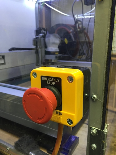
- Purchases a 15A Power strip with a 6 foot cord ($4), and a cheap orange extension cord ($8, 15-25ft, and an EStop switch (NC, $7) with enclosure (Amazon, eBay, Banggood, etc).
- Open the power strip and find where the black wire is attached to the inside and unsolder this connection.
- Drill a 1/4 hole in the power strip so that you can feed the orange cord inside the power strip
- Cut the ends off the orange extension and feed one end into the 1/4 hole in the power strip
- Strip off 2 inches of the orange insulation and then strip off about 1/2 of all three wires.
- Connect the white wire to the incoming black wire of the power strip
- Connect the black wire to where the power strip Black wire was attached
- Connect the green wire to the green wire in the power strip (Close the Power strip)
- Open the E-Stop enclosure and connect the white and black wires to each side of the switch and the green wire to the green terminal. (Close the E-Stop enclosure)
- Mount the E-Stop in an optimal location
- Plug in the Router and 24v power supply (and anything else you want to cut the power) to the Power Strip.
Turn on the system and test.
Hit me up with any questions or details that I might have missed
Thanks to you both. I think this is in my wheel house of abilities Rich. I will give it a go soon 
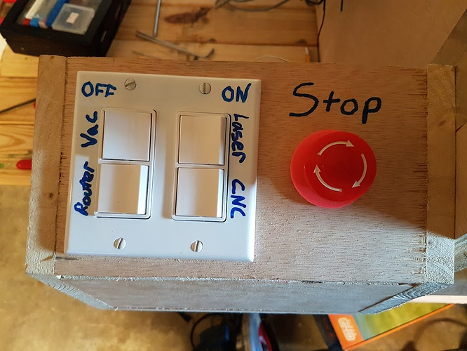
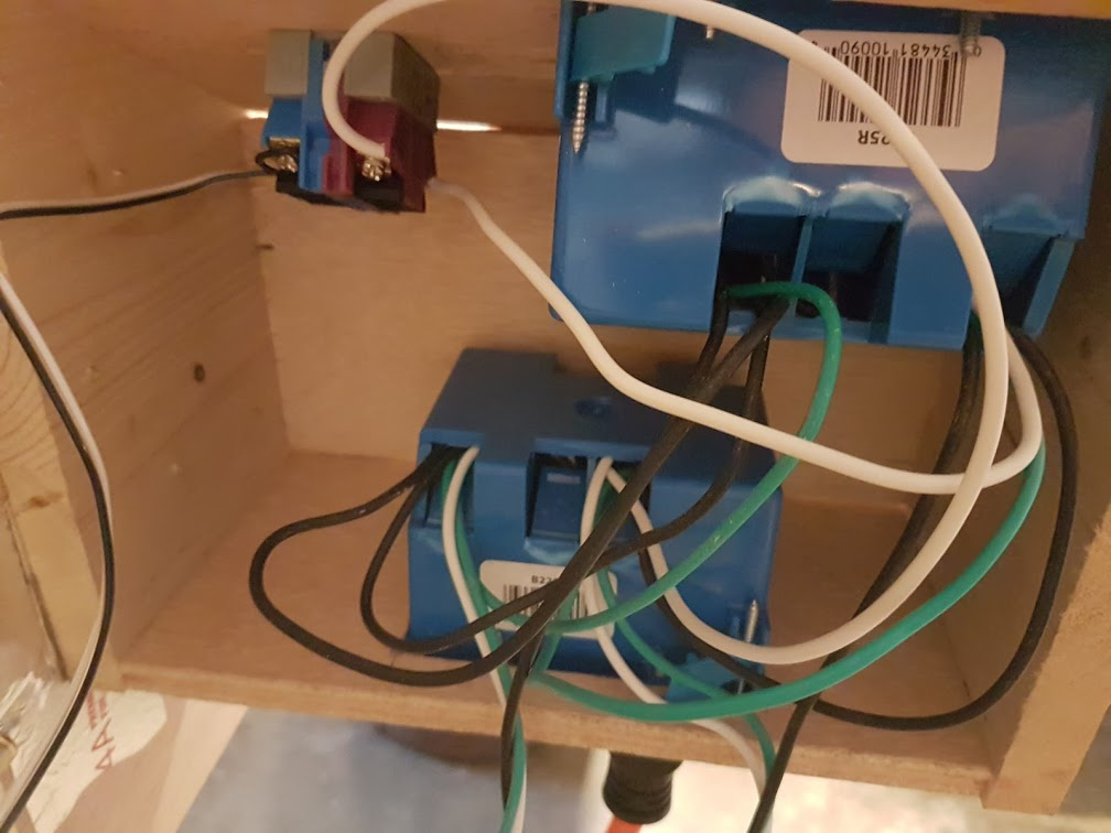
What you see here is, I installed 4 switches. each have individual sockets directly under them. The E-Stop is in series with the router hot wire. My E-Stop button has 2 separate sides one goes to the mains with the router the other is connected with smaller wire to the E-Stop pins on the controller board. When I hit the button the router stops and so does the controller. It DOES NOT power off the controller board it DISABLES the motors instantly via the controller board estop pins. I can power off the router with the switch on top and at that point reset the E-Stop button. This releases the motor disable. Unfortunately you will still have to RE-HOME after that event happens but I don’t have to re-connect my computer or software to the board at that time I just hit the home button.
It’s just an extra set of wires running off one side to the controller board this way.
Mine is here:
https://www.amazon.com/gp/product/B01BLJ6ES0/ref=oh_aui_detailpage_o06_s01?ie=UTF8&psc=1
One side is normally closed (This side is mains to router)
The other side is normally Open (This side to E-Stop pins)
When you hit the button the router side breaks. The e-stop pin connects and when it connects is releases (disables) the motor driver circuits.
I hope that explains it, if you have questions let me know.
Hello, fairly new to the forum, so if this has been answered previously my apologies. Trying to setup an EStop button as described above, but don’t see any EStop pins on my board (2.4C). All I see are xyz limit pins, probe and feed hold. I’m thinking feed hold will essentially do what I’m trying to do. I plan to cut power to everything, router, dust collector, yet leave the board powered up minus steppers. I already have a NO/NC dual pole button, so I can cut power where I want to while closing the EStop on the board, but the pins aren’t on my board that I can find (albeit I’m waiting on a new pair of glasses, so I’m flying half blind, haha!!). Any suggestions? Will crossing the feed hold pins work? What’s the difference between EStop and feed hold?
Thanks in advance!
Dan
E-Stop is the oh shit button that shuts everything down, and Feed hold is as it sounds, stops the machine from Feeding, but NOT Rapid which is where most accidents occur.
I chose to stop everything, ALL power and it’s esy to install (See above), but if you have the time and knowledge, you can shut down the power to the motors, and spindle only (also see above Roger’s comments)
Oh, so feed hold will not work the way I’d hoped, bummer:-( Sounds like the actual EStop pins would work though, unfortunately mine are MIA. Had my girlfriend, who has much better eyes (among other better things) look all over the board for those pins and no luck. I may have to rethink this. My board is powered separately from everything else on my bench, vacuum, spindle, soon lighting all on one circuit, board on a completely different circuit, so cutting power to those while just closing the EStop pins would have worked pretty easily with a dual pole NO/NC big red button. Bark to the drawring board!
Thanks,
Dan
Remember even IF you had an EStop pin on the card, it still would NOT stop the spindle (Router) because the spindle is not being powered from the controller card, right? The spindle which is the one that will probably do the most damage if something goes wrong, so stoping the spindle (Router) is a must too (as well as the stepper motors.
Yep, totally understand that power needs to be cut from the router as well, and I can currently do that no problem. But I also want the steppers to stop, and that’s what the current problem is because the board/steppers are on an independent power circuit from everything else on my setup.
Thanks,
Dan
Easy enough to do with a single EStop button and a few relays…
The estop switch Roger linked to above has a NO (normally open) side that is connected to the estop PINs on the board. The NC (normally closed) side of the switch is connected to an outlet that controls the router. I have the exact same setup as Roger and can verify that it stops the motors and turns off the router when I press the button.
The estop pin pair are between the Z limit and the Probe pins on the board. So it is the 4th pair from the left, or 3rd pair from the right. I have the 2.3 board, and it is clearly marked.
This is exactly what I’m trying to do, however on my board (2.4C) there is no EStop pins. I have XYZ limits switches, then Probe, then Feed Hold, looks like my revision of the board omits the EStop pins, at least in the location where they are normally found. I have the stop button, similar to above with two poles, one NO one NC, but nowhere that I can find on the board to connect the NO side. That’s where I get stuck, it appears the board has changed a bit lately. Does anyone have this late model board (2.4C) and found where the EStop pins are now located, or can C3D confirm that they have been removed altogether?
@RichCournoyer: I’ve thought about running a relay to kill everything, but I don’t even want the 1/1,000,000 chance of a relay sticking or some other part of my Rube Goldberg contraption failing while the machine is chewing away at my chihuahua that somehow jumped up up on the bench and decided that licking the running spindle is a good idea;-)
Thanks for the help guys!
Dan
I recently installed (a few months ago) the 2.4 board and can confirm that there are fewer pins on this board, but I can’t recall which pin has been removed. I’ve searched for a GOOD photo on this board and there doesn’t seen to be one.
I will open my board cover in a few days (to install a GCode Spindle switch, but that’s on another discussion), and will photograph it.
Dan: I’d email support and see if they can tell you where the estop pins are. Surely they did not remote that feature?
I would think that feature, albeit unsupported would not have been removed, but I can’t find it anywhere on the board. Maybe it was re-implemented somewhere else on the board? I dunno? I emailed support, hopefully hear something soon. Thanks for the help, I’m sure I’ll get there one way or the other:-)
Dan
Sorry to hear there is no e-stop pins any longer. I really like mine. I hope support comes up with a work around in-case I ever have to change out my 2.3 board?!?!?! On my board it is clearly indicated as estop. I can tell you it does stop during any motion rapids or not, I have used it many times. It’s a great insurance button for me.
I got to look at my board today and V2.4(No Letter) has NO E-Stop pin. BUT I also see that the E-Stop button is no longer on the Nomad either, just a power switch. So you might want to go with my easy E-Stop method above.
Yea, I hadn’t revisited this topic, but I did receive a support email stating that the EStop pins had been removed. From my understanding this was never really a supported feature on the SO3, and the Nomad now uses a different method. A bit of a bummer, but I totally understand why this would be done since the machines share the same boards, and the machine that used those pins no longer uses them. I was also given some guidance on how to make this work with the current board, which is basically to cut power to everything. I picked up a relay and plan to go that route pretty soon, just have a few other projects in line ahead of it now(like capturing the raccoon family that has recently made my attic home…caught one already, live trap, pretty good deal for them, they get a free meal of canned cat food then released far away…I pay for dinner, short term housing and transportation!!!).
Thanks to everyone for all the help!
Dan
Please be very careful handling the critters, and clean up their droppings very carefully — they can have some nasty parasites/bacterial infections.


