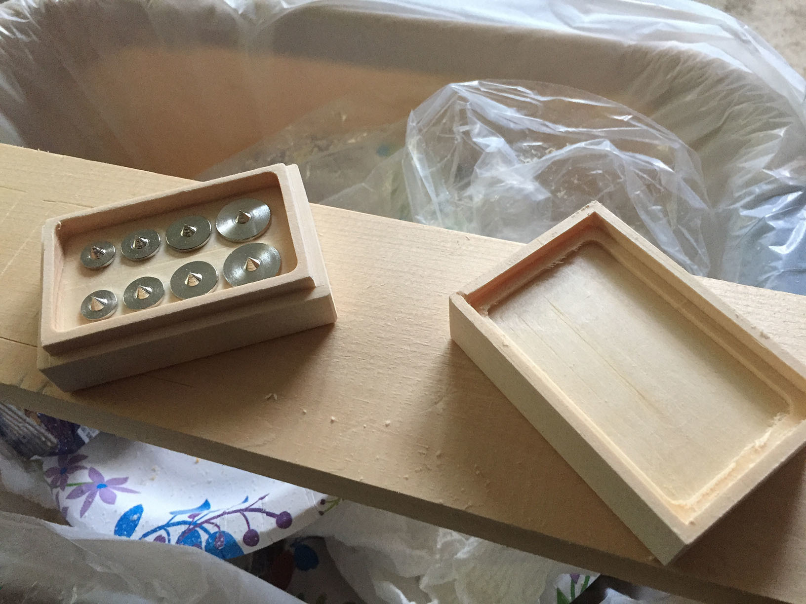
curious how one would go about making a box with a lid like this. the idea is that the lid slides on tightly and creates an airtight seal so the top doesn’t come off unless you pull it.
Don’t need the fancy joint work, just regular 45 degree cuts, I am just curious how one might make a lidded box like this.
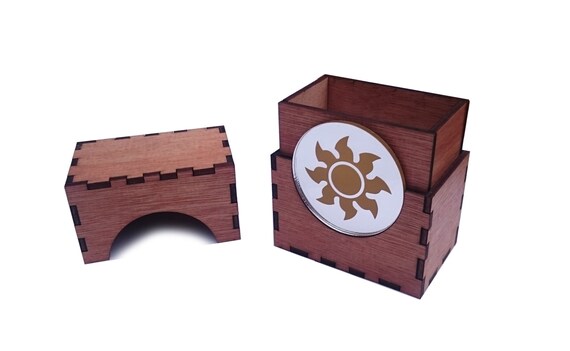
thank you for sharing. I was thinking of something more along the lines of this. But minus the ginormous circle. So the lid would be able to slide on, but even if you flipped it upside down the suction of air from inside would not allow the top to slide off. If that makes sense?
interesting, I have an idea about how I could achieve this without a laser cutter, but I am still baffled as to the zero’ing and tool changing process haha. I will have to flip some pieces over after they have been cut once, how can I ensure the CNC will be precise after a tool change and cut properly?
Ok, take out your note pad and pay attention. It is very easy, and very easy to screw up. You should be using the latest version of Carbide Motion, and have at least 2 programs (one for each tool) to machine the part using the same XY&Z0 position.
Step 1. Home the machine
Step 2. Clear the offsets. The machine coordinates should read XYZ = 5 mm
Step 3. Find the part that you want to machine XY and Z0.
Step 4. Click on Zero ALL.
Step 5. Run your first program with the first tool. Ready for a tool change? Read on:
Tool Change:
Step a) Stop the spindle, and Jog the machine X, Y and Z to a position that is comfortable to access the tool. (I like to click on the pre-set rapid position Front Center)
Step b) Change the tool.
Step c) Raise the Z almost to the top.
Step d) Click on Rapid X and Y position. (The machine will remember the XY and Z positions even if you turn off the machine, but since you have changed the tool, the Z0 needs to be reset.
Step e) Carefully lower the machine, so that that the Z is a sheet of paper off your part.
Step f) Click on Zero Z
Step g) Raise the Z and start your next program
Feel free to ask any questions. but read this first (Maybe 3 or 4 times)