Hi gang, brand new to CNC with my Pro XL and did my first 16 inch circle cut last night.
2 big takeaways…
If you are going to use the material center as your “starting point” then make sure your starting point in carbide create is also centered (not lower left). That was a horrible noise.
when trying to cut a 16 inch circle make sure your material is not further back than the gantry will go. That was another horrible noise
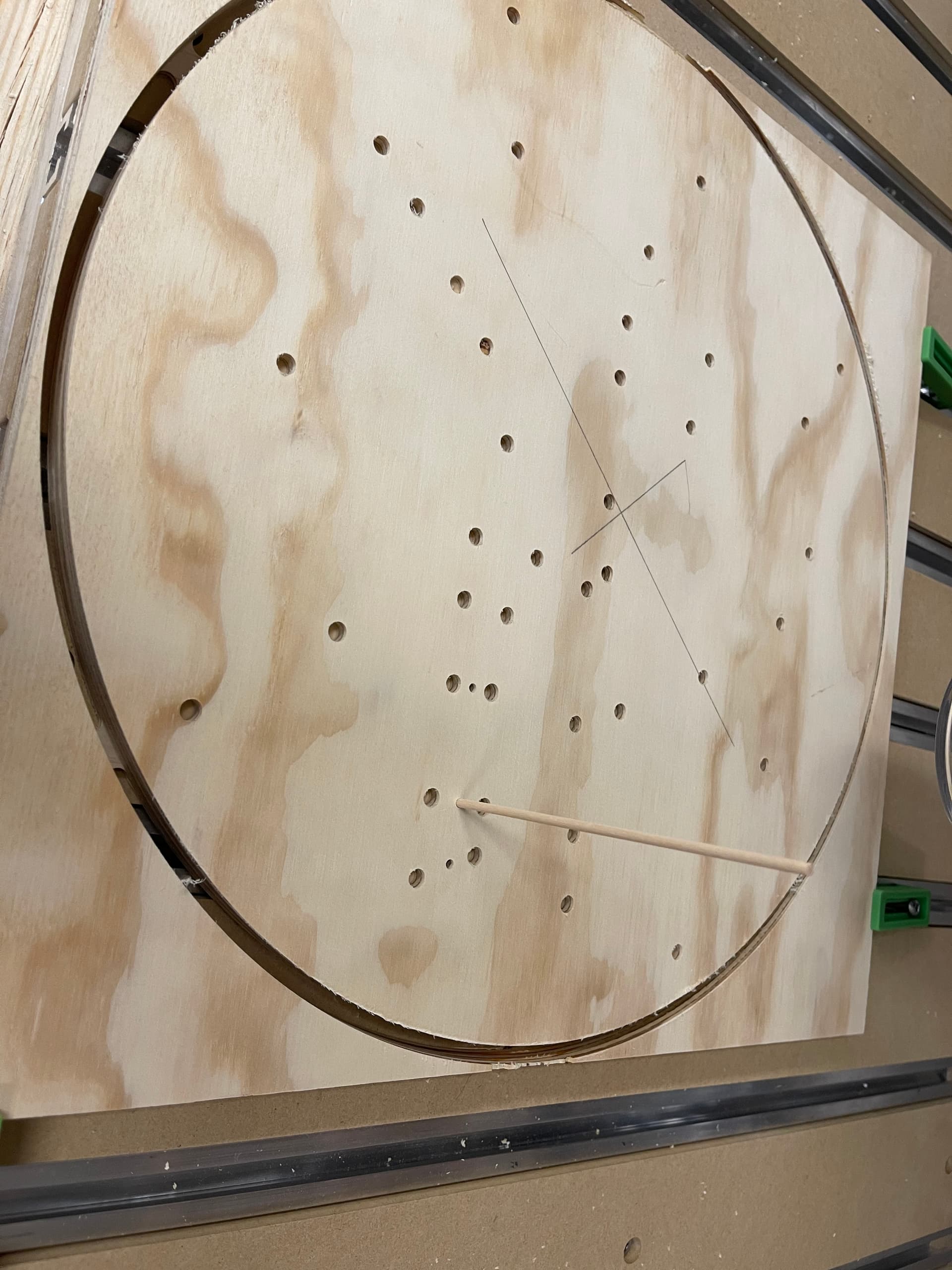
So i tried to make holes in my plywood, 1/8 inch wide and 1/2 inch deep. I used the 1/8 inch endmill but no matter what i tried all the circles came out to be 1/4 inch wide. i tried everything and then read that you can’t plunge cut with a CNC. So my question is how can i make 1/8 inch holes?
thanks in advance, super excited to be part of this community
so the OUTSIDE file is 3/4 inch plywood and the holes are for 1/8 inch dowels
the FLIPPED file is 1/2 inch MDF and the holes are for 1/8 inch dowels
i read somewhere that the dowel trick is helpful to keep your design aligned and the file is flipped so the dowel holes would be on the back of the artwork
So I think the problem is that you’ve chosen a “Contour” for the type of toolpath for the circles…and put the No Offset option on. What that does is center your 1/8" bit on a 1/8" circle, meaning half of that bit is outside of the circle…so you’re effectively adding 1/8" to your 1/8" circle = 1/4" circle.
You can either use a smaller bit and POCKET the circle, or use a 1/8" bit and DRILL the circle. That’s the toolpath choice that will work.
EDIT: You could also use a 1/16" bit and CONTOUR the circles with an INSIDE option. Which would effectively do the same thing as a pocket, but maybe more efficiently. But I think the DRILL toolpath with a 1/8" bit is the best choice.
drill path for the win!! i had only known to use CONTOUR and honestly didnt understand the rest of the tabs. you can see after accepting my fate of having 1/4 inch holes i just now cut the 3 successful holes that fit the 1/8 in dowel perfectly.
Gary, thanks so much for your help, i really appreciate it
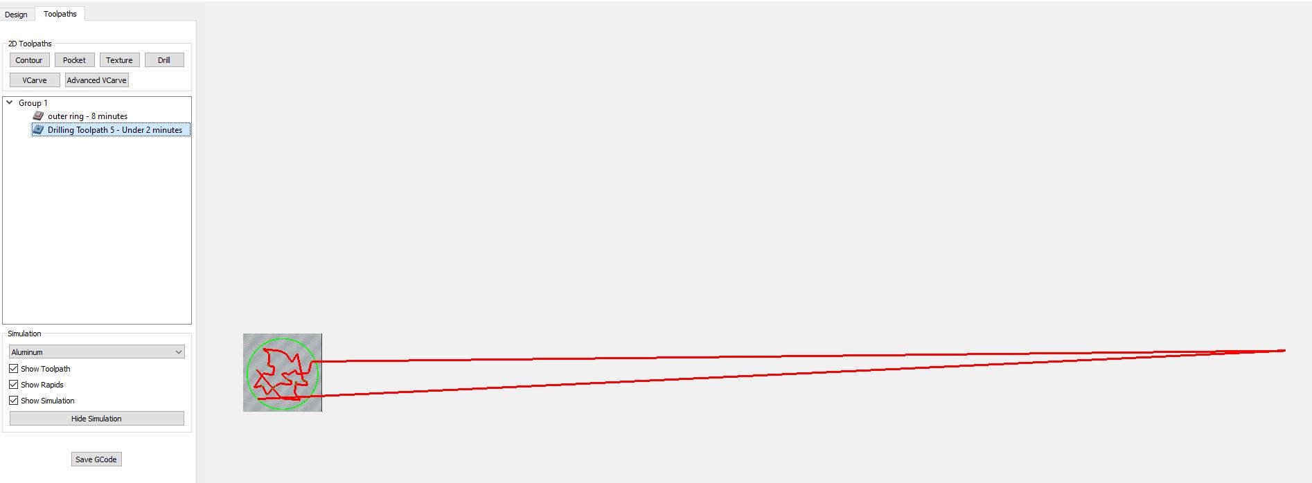
hah, yes it should be. everything was fine until i added the drilling toolpath then the simulation went wonky. i drew everything in the design tab and then added all the holes to the drill path under toolpaths. 16_outside_V2.c2d (986.8 KB)
yup, found some little guy stranded waaaay off the screen. how he got there is anyone’s guess. That’s why i shouldnt select all when creating a new toolpath.
You checked the toolpath before running it, that was the sensible bit, I never run a toolpath without viewing it or watching the simulation to see what clamps it’s going to plow through first
You’re right, it’s a lot of effort for one-off jobs.
I model fixtures where I’m using them so that I can see locating dowels, bolts etc. and try not to send the cutter through them. I also modelled my 100mm jaw vice and can import that into the model when I do CAM to show how the workpiece is held and where the heavy parts of the vice are.
For ad-hoc clamping onto the spoilboard I watch the simulation and then place clamps in areas which seem to be clear, or I tweak retract heights on the paths which rapid through areas I want to clamp.