Recently got a 220v water cooled spindle kit from HY (amazon purchase). Ive been able to get it to work manually but after putting in so much time with no luck having carbide motion control the spindle I have to finally ask for help… The vfd works great manually, as soon as I change pd001 and pd002 to “1” the vfd displays continues to flash all zeros with the corresponding letter to whatever its set to display (F =frequency, A= amps, ect). However after reading previous posts Ive been able to confirm proper pwm voltage based on GBRL input… enter M3S12000 and get 2.5vdc between pwm and acm. The vfd display will even show the correct frequency to let me know its recieving proper signal but just keeps flashing (f200.00, or when checking others still flashing and all zeroes behind corresponding letter). 244v going into vfd and proper control signal present however no output voltage to motor until I switch vfd programming back to operator (manual) mode. Any help would be so greatly appreciated.
There’s an old thread on here about water cooled spindles that there are some nice write ups on what needs to be done.
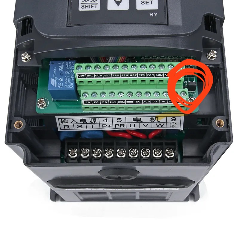
You’re going to need to make a mechanical jumper on the vfd. Plus install a jumper wire to make it only go forward.
With all that said the signal from the controller did not play nicely with my hy vfd on my 5 pro. Made it unusable Apparently there’s another circuit board on the carbide model vfds that make it work.
I ran by inverters on both my s3 units for 5+ years with the controller commanding the vfd. Now I just control it manually on my 5. Which I’ve also posted about on here.
I thank you for taking the time to write. I do already have that jumper from dcm to for and have also disabled reverse in the vfd programming because I have no need for reverse. The odd thing is I am syure I seen someone with a similar problem (vfd continuously flashes) and how they solved it but for the life of me I cant find it. The thing is Im confident my carbide board is already sending the correct signal to my vfd and am even getting the correct frequency displayed on the vfd which correspobnds to both the gbrl code I entered and the dc signal voltage being sent from carbide board gnd and pwm soldered terminals to hy vfd acm and vI terminals. Wierdest part is VFD will spin when I set it to operating and manual adjust frequency at pd003 but as soon as I switch pd001 and pd002 to “1” and then enter gbrl code at carbide motion, the vfd will only display the associated frequency but wont actually act on it by sending the associated power to the motor. GRRRRRR… these things! I must have 30hrs in you tube and online searches over last couple weeks trying to learn all the ins and outs of these things. Appartently I need more time. lol
I honestly don’t know what settings it could be, but for what it’s worth here is the “old thread” back when we were discussing how to make those Huanyang VFD work:
My suggestion would be to go down the list of VFD params and do a side by side comparison with the value on yours (not saying they should be set to the values in that thread, but it may allow to spot something to investigate)
My other suggestion would be to do a factory reset then reprogram the values you need: sometimes we THINK we have them all under controls, but we don’t.
Good luck, I feel the pain of being so close yet not quite there!
The first post in this thread breaks just about everything down.
There is also a plastic jumper you have to move on the vfd from one position to the next. Read the manual to make sure as it’s been a while.
This topic was automatically closed after 30 days. New replies are no longer allowed.