I chucked it all up

Hey everyone! I’ve been sitting on this post for a while, but I’m pretty excited about it. I know there have been others that have done a rotary axis, and I have always wanted to try it. I finally realized that, with three kids (not counting the SO3), I have no free time. My hopes of DIYing a 4th axis aren’t going to happen. I went with an “off-the-shelf” version, and I couldn’t be happier with the outcome.
I wanted to share my experience with connecting a Vortex Rotary Axis from Sienci Labs to my trusty Shapeoko Pro. I really didn’t know what it would take to get it going, but I figured it was made for a grbl based machine/controller so it should work, right?
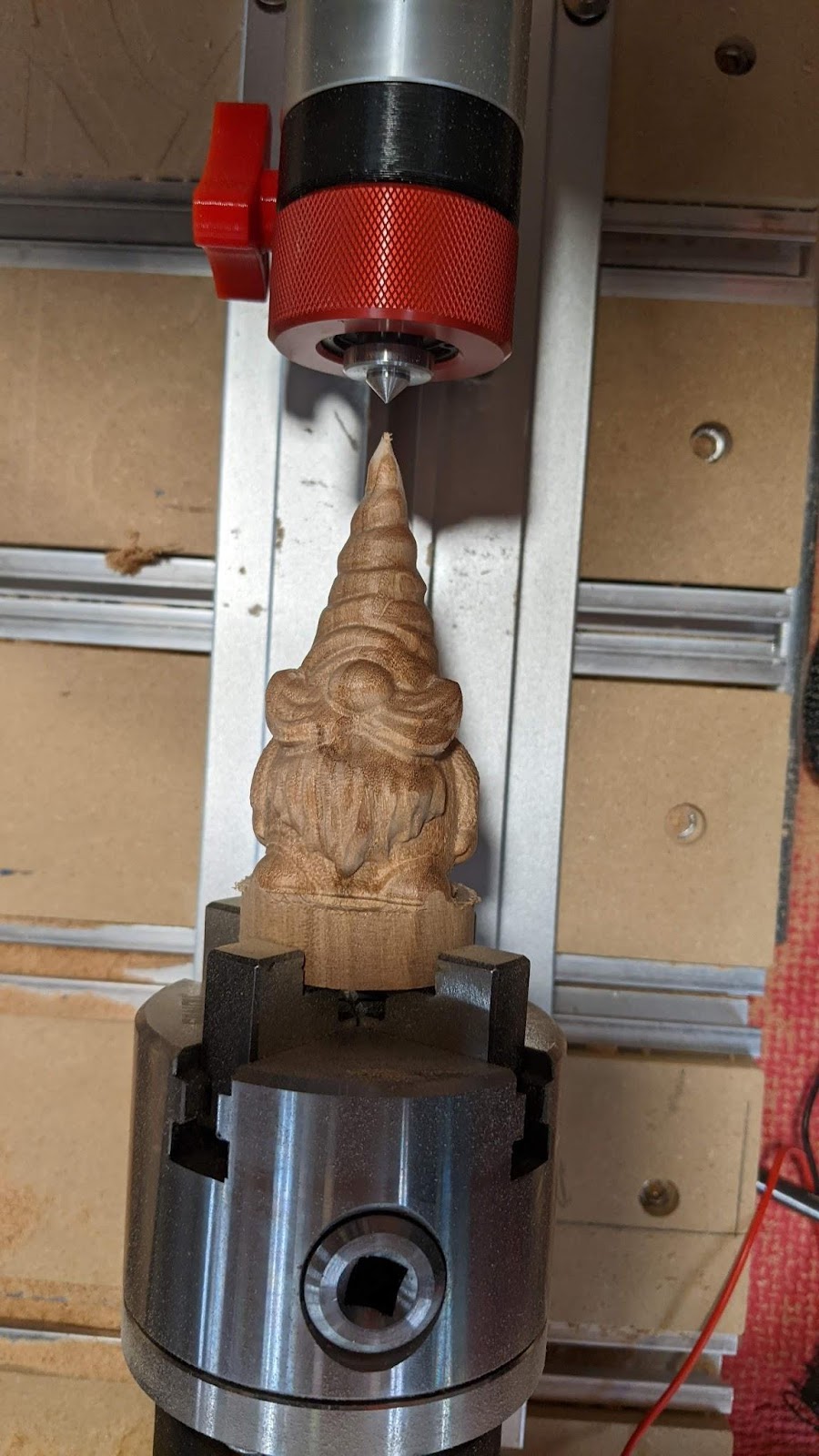
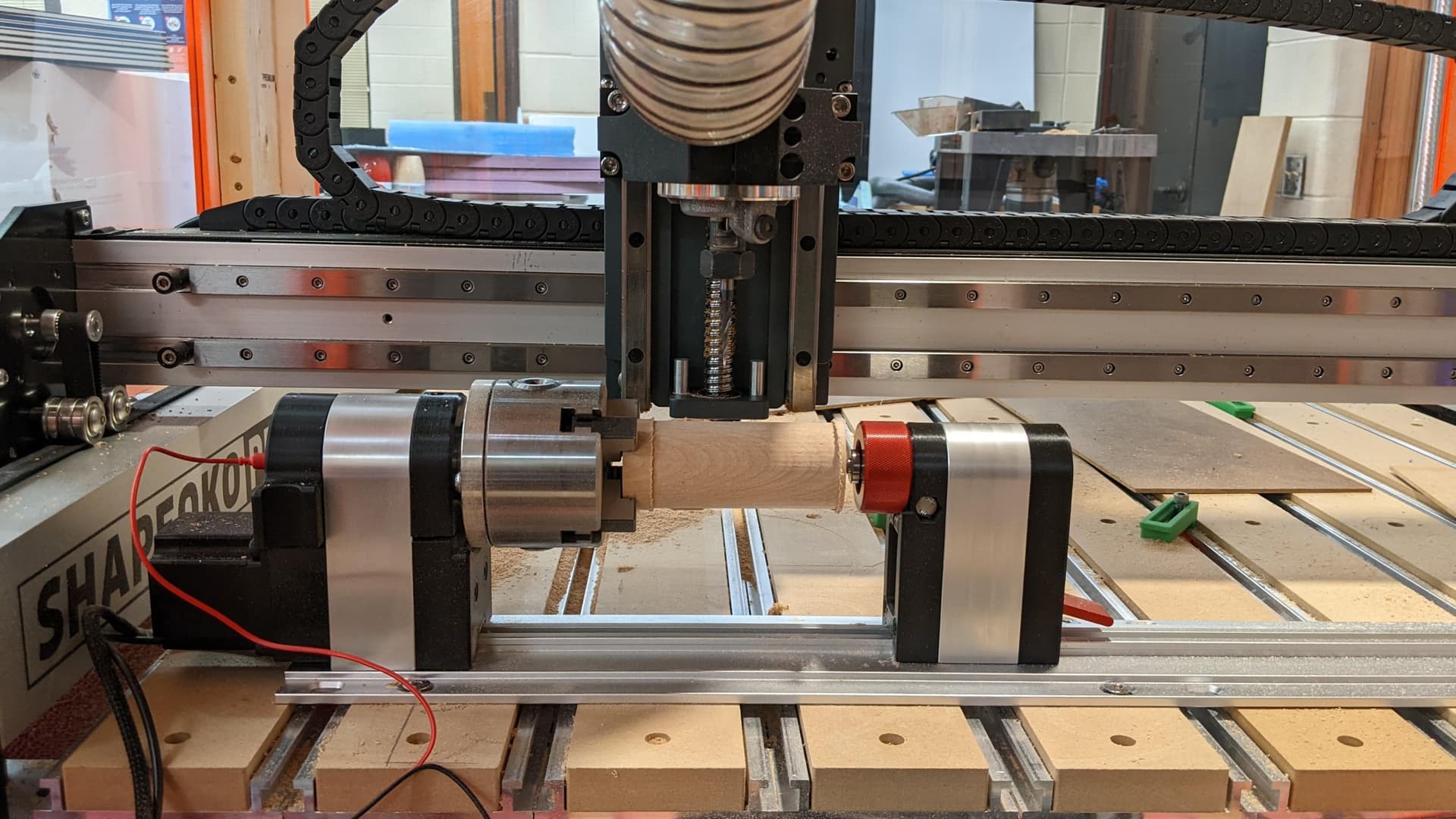
First, a look at the first attempt at a rotary carve:

After getting the Vortex, I was impressed by the simplicity of it all. It’s really just the chuck, tailstock, and a custom extrusion to mount it to. The part that really impressed me were the integrated, 3D printed parts that make homing and probing seamless…more on that later. I was also impressed with the online assembly and getting started documents from Sienci.
It’s really solid and fairly easy to remove and put back in place when going from Rotary to Y.
I fully expected some challenges with the main three being: wiring, aligning it to my X axis, and keeping the Y in place.

The vortex comes with a switch that allows switching from Y to A for rotary jobs, but it simply disconnects the Y motors and connects the rotary (A) motor to the controller. This should only be switched when power is off, by the way. I knew that would not be enough on the Shapeoko Pro (or 3 or 4 or probably HDM and 5) because of the belts. This just leaves the Y free to move. I thought about shorting the Y coils when the switch is flipped to A, but that holding resistance is too weak to do much. I next toyed with using multiple relays to connect the Y motors to a separate controller that would simply put the Y steppers into a hold state. I finally settled on just clamping the thing in place, guessing that I was overthinking the whole thing (I tend to do that sometimes)…more on this later.

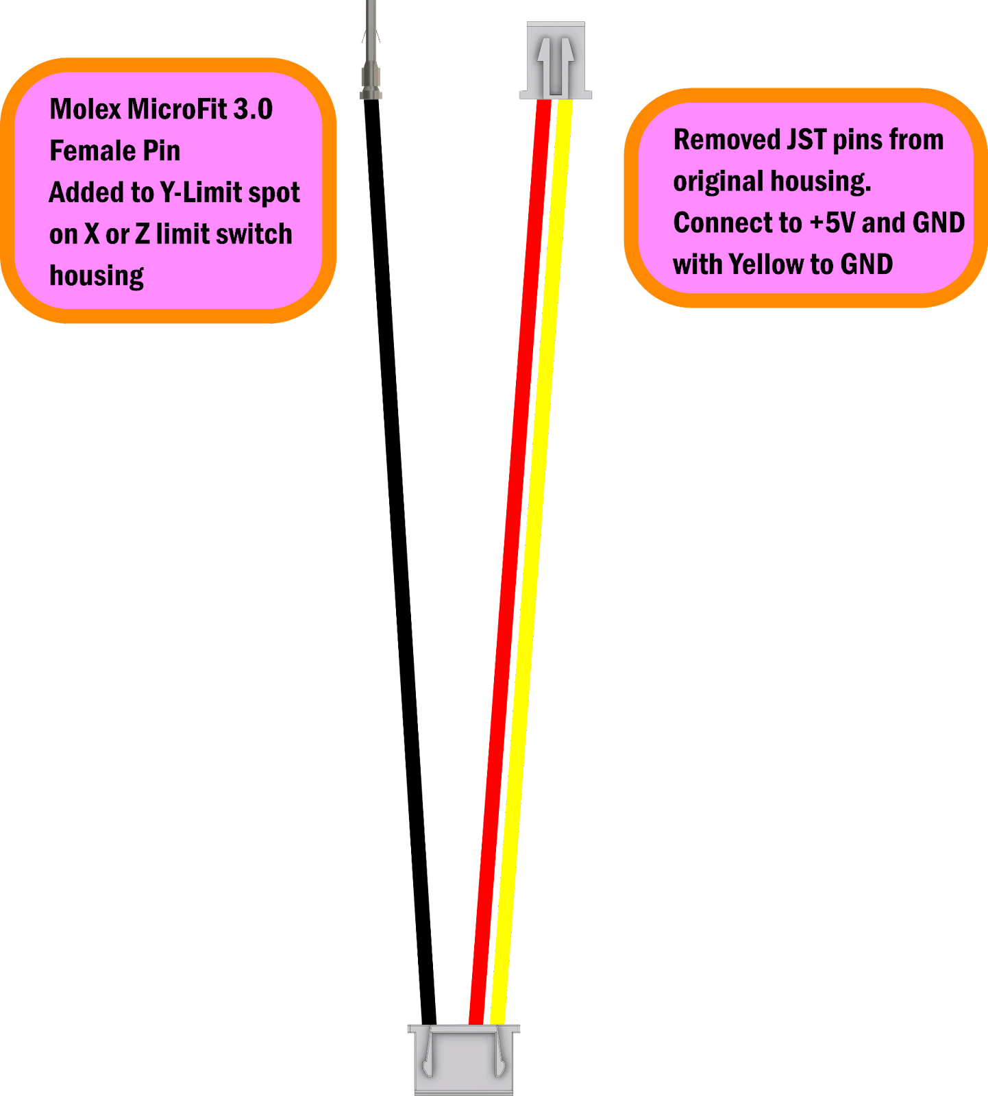
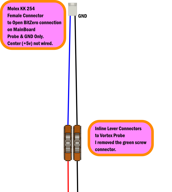
My next mission was to handle the wiring…ugh…the variety of connectors. Luckily, I teach electronics, so I had some connectors and tools on hand. After an Amazon and a DigiKey order I was able to make the necessary adapters.

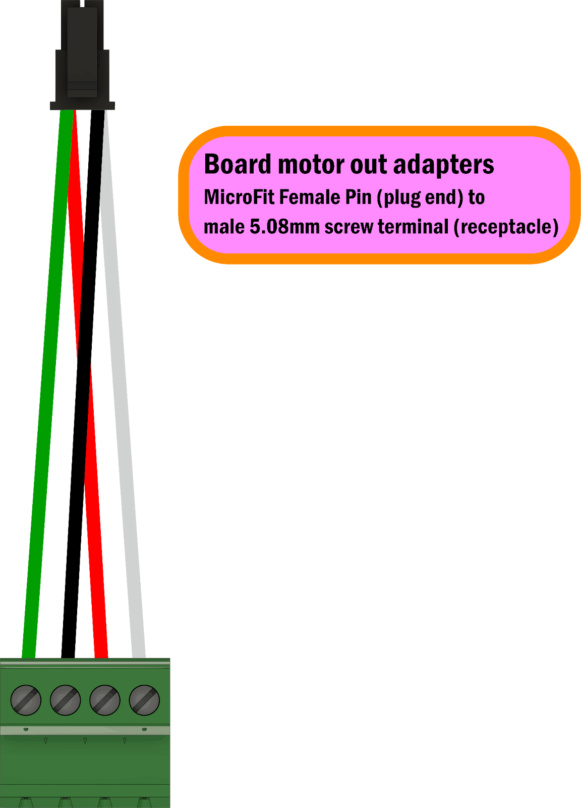
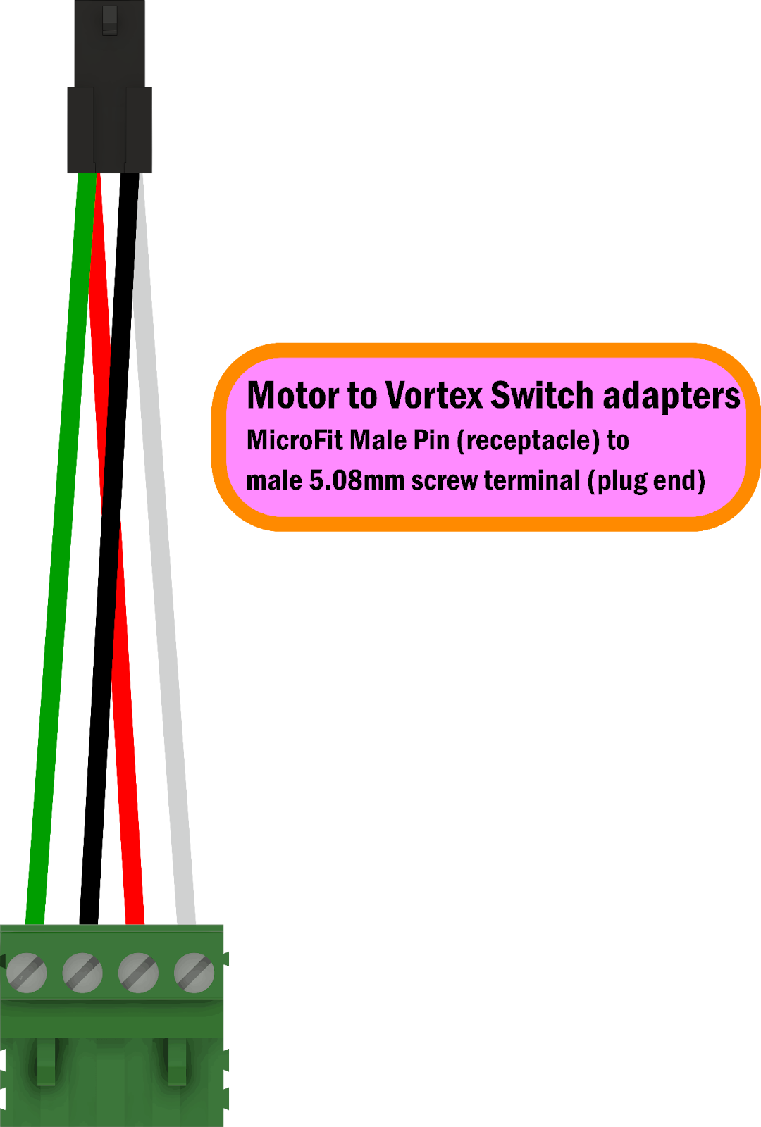
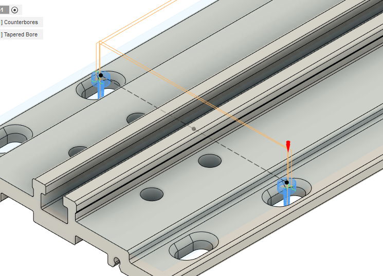
After I got these adapters made, I thought I’d just mount the thing, clamp the Y and go. But, how do I mount the thing? Well, gSender has a built-in gcode generator for mounting the Vortex (They use ¼-20 threaded inserts). There’s a problem though, because I don’t have a Longmill…I have a beast of a machine called the Shapeoko Pro. Not to worry, I used their open source files to generate gcode for the mounting holes that would fit on the MDF slats on the Pro. I generated some counterbores and tapered bores to match the taper of the threaded inserts. I also set my Y-Zero in Fusion to be on the centerline between the two left holes. That way, I could decide where the Vortex fit the best, zero Y there, and hit the slats exactly as planned. gSender also generates gcode for hole pairs, but I’m comfortable with my Fusion workflow so I went with that.

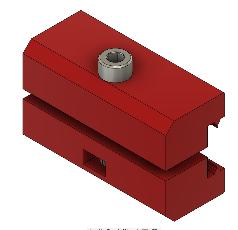
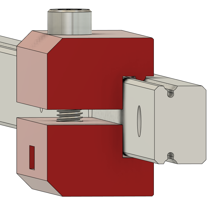
Great…easy. Now I just have to clamp it and go! I tried every which way to clamp the Y-axis on the SOPro, and I could not find a consistent method that prevented the Y from moving. After way too long, I finally came up with little 3D printed linear rail clamps. They clamp on the Y-rails in front and back of each Y-plate. I made a split clamp design, so I don’t have to slide them on from the front and rear of the machine. That’d be obnoxious on an XXL. Here’s what those look like:

Once that problem was solved, I was ready to go.

The procedure is pretty easy:

  1. Home the Shapeoko normally.
  2. Use gSender to set “Y-alignment”…this basically ensures that your X-axis is centered on the Vortex. I chucked up (doesn’t sound right) an aluminum tube to do this because the Vortex chuck is too tall to run the probe routine on the chuck. I’ll probably write a macro to do this without the tube eventually.
  3. Once aligned, I installed and tightened the clamps (while the Y is still powered).
  4. Power down, flip switch, power up.
  5. Set rotary mode in gSender (this adjusts the steps/mm for rotation)
  6. Home machine again…it’s fun to see the Rotary axis home!
  7. Set X-zero, as normal, by eye.
  8. Set Z-zero using the built-in probe routine, probing the chuck. This sets Z-zero in the center of the stock which makes sense for rotary jobs.
  9. Run the job!

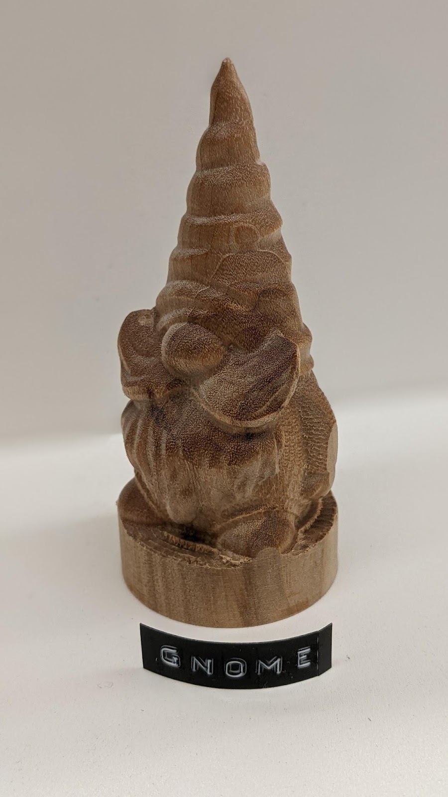
I downloaded a gnome stl by Body3D on Printables. I used V-carve Pro (v 9.5) and a custom post processor to generate the gCode. I used a flat ⅛” tool for the roughing, and a tapered ball (0.5mm tip) for the finish. I rarely do 3D reliefs, so I was impressed with the results.

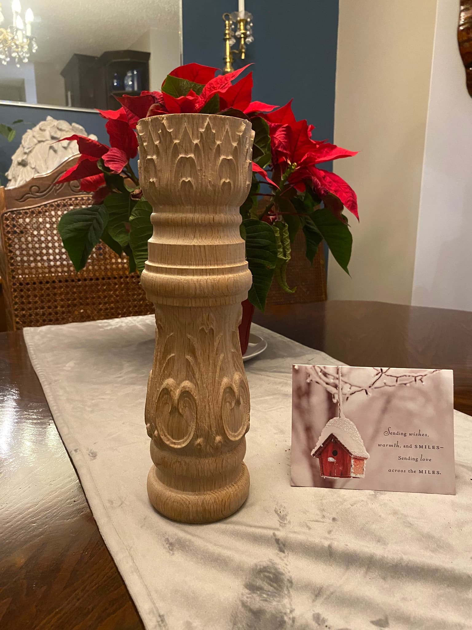
Sorry for the long post! This was a fun project to get working, and it’s so cool when things just work! Not sure of my next rotary project, though a custom tap handle sounds like an obvious one.
Let me know if you have any questions. As always, I can share any STLs, files or post processors if you’re interested.

TLDR: Made my Shapeoko spin.

43 Likes

Very cool Neil. Much appreciate the detailed explanation and the labled diagram with parts description.

This is something I’ve long considered but outside my limited skill set.

Book marked for future reference. Thanks for taking the time.

1 Like

That’s really nifty!

What do you figure is the largest diameter stock you could use with that rotary axis?

And, would it be possible to mount it just in front of the SProXXL bed & still have the spindle reach the center of the rotary axis?

1 Like

As with most answers to this type of question, it’ll depend on what you’re making, endmill stickout, and depth of carve. Sienci says 4" max, but I’m guessing their assuming one of their CNCs. From memory, there’s about 80mm of clearance from the tallest part of the extrusion base to the center of the stock. I know I had my router about as high up as I felt comfortable.

I thought about this, but, if I recall, it didn’t reach. I’ll check tomorrow.

Dude! This is TOTALLY cool! I’m just getting started with CNC, so I am way far from this. Congratulations. Awesome!

1 Like

Very interesting. I’m trying to do something similar myself although not with the Vortex hardware. Could you please explain how you handled the limit switches? What post processor are you using?

I’m not sure which aspect of handling the switch you mean, but I’ll try…
The Vortex comes with a switch that not only switches the motor but also has connections for the limit for the Y limit switch. It’s not actually switching which switch is connected to the controller. It just facilitates connecting the rotary switch and Y-limit switch in parallel.
Do you have a Shapeoko Pro? The limit switch connectors on the controller are all connected, but the holdings are not fully populated. Basically that means that you can add a pin for the Y limit switch (rotary) to either the X or Z switch connectors. I pulled 5v and ground from another available pin on board.
Does that make sense? Answer your question?

The post processor is my own for V-carve. I don’t have access from my phone, but I’ll upload tomorrow.

After I bought my 5Pro my old 3XXL started gathering dust and taking up room in my shop. So I thought I could put it to some use by installing a horizontal axis on it. If I get it to work properly this machine will be used exclusively for that purpose.

I bought a rotary axis unit off Amazon. It seems to be a good quality machine but there is no supporting electronics at all. Just the four wires coming out of the stepper motor. So I’m left to figure out the rest on my own. Since the gantry never moves in the Y direction, the existing Y limit switch is never triggered. The simple solution would probably be to just mount it on the X axis beside the one that’s already there but being a guy, I was looking for a difficult way to do something easy. I was curious to know what you did and your comments were helpful.

It’s the post processor bit that’s the most challenging. I don’t have any experience with designing or modifying post processors and I’m looking forward to seeing the one you used.

Are you going to have a homing switch on the rotary axis? If not, you could always disable homing or modify your Grbl config or simply unlock the machine rather than home.
That said, being able to home the axis was on my list of things to solve and a reason I just went with the vortex. They use an inductive proximity switch to do just that. They also integrate the probe which is really helpful for lining things up.

I promise I’ll get that post shared soon. Busy time!

Let me know if you need more info or clarification.

Very cool. I am intrigued, as I wanted to do the same on my Shapeoko 3 and tried a poor man’s hack… at the time I was interested in purely symmetric pieces, so I “tricked” the machine.

  • modeled up my part in Fusion
  • in the CAM section, I restricted the machining area to a 1mm slice at the top of the part
  • this exported, essentially, a simple back and forth following of the silhouette
  • I bought a cheap 4th axis on amazon and wired up to a power supply and simple arduino board + potentiometer to spin constantly, with me changing speed via the pot

It was… ok. The 4th axis I used is belt driven (motor shaft has a toothed gear, coupled to rotary axis shaft itself with its own toothed gear), and I found that to get the slop out, wrenching on the belt tension significantly increased friction which tended to stall things out. I also found the axis to stall at higher speeds much more easily (I’m sure if I read into stepper speed vs. torque theory or something this would be obvious).

Anyway… having something actually controlled would be awesome.

This would seem to make it obvious, but this is the route where one purely stays with 3 axes: x, y, z or x, z, and a? I had similar feelings (perhaps due to also having a similar number of kids :slight_smile: ) about upgrading my board to support full 4 axes. Tough to balance wanting to do things vs. the time required to build it.

For some additional questions:

  • Am I right you got this kit?
  • any reason this wouldn’t work on an SO3?
  • I don’t have an SO5; I can’t see, but think there must be linear rails on the outside of the y rails that the x rail rides front/back on? Am I interpreting correctly that you used 4 sets of clamps, one in front/back of the x rail on both the left and right?
  • could you elaborate on how you generated the gcode files? I’ve dabbled very minimally in Fusion360’s rotary output… you mentioned gsender, which I think purely sends gcode (like a Carbide Motion analog?)… does it generate the paths from the 3d file as well?

Great stuff, thanks for sharing. I know many think the RightWay is a much more comprehensive upgrade but given those with $ and time limits, it’s awesome to have additional references on how folks have done things like this :slight_smile:

I made a few modifications to my S3XXL over the last couple of weeks and got it to produce this on a horizontal axis.

8 Likes

Sorry for the late replies! Holidays got the better of me.

I forgot I had uploaded the post processor to github a while ago.

I did modify Line 42 to be “A” instead of “Y”, as gSender just translates it. I believe it also recognized it as a rotary program (I will double check the effect this has). Ultimately, gcode is sent with a Y to the controller anyway.

Yes.

Nope…I think I might ultimately use this on my 3. We’ll have to re-solve the clamping issue, but I think it’ll be simpler… :grimacing: (I know better than to say that)

I did this on a Pro (not a 5 Pro), but your interpretations are correct.

This was all done in V-Carve Pro (9.5). I’m looking into other options as well.

1 Like

I’d like to know where you’ll find the room to do any Z travel on the 3.

1 Like

Hmmm…
HDZ + baseboard mounted underneath the endplates. Once you lift the router up in its mount, I think you might have the clearance. I’ll obviously update when I try, but that may be a while. If I really find a reason to have a rotary dedicated machine, I think it’d be easier to just build some fixed, taller “Y” plates that are attached to a base. Probably easier to use off the shelf components from OpenBuilds or similar, to max out the length.

1 Like

In my dreams, I’m going to have a “big boy’s” cnc and dedicate the 3 to rotary by mounting the rotary through-the-bed/raise-the-bed. In my dreams, at least.

2 Likes

Thanks for this. I enjoyed the holidays too and had fun messing with my old SO3XXL. I managed to get a rotary axis working as you can see in an earlier post.

The rotary axis I’m using is “CNCTOPBAOS CNC Router 4th Axis Rotational A Axis” available on Amazon.

It is simply a stepper motor driving a chuck with a 6:1 drive ratio. No limit switches or any other smarts. All the documentation you get is in the Amazon description. No docs in the box. Physically however, it seems to be a pretty well built machine.

Since I wanted to use Carbide Motion (I’m familiar with it) and drive the horizontal axis with the SO3 controller (It’s on the machine) I had to invent a few workarounds. Because there is no longer a need for Y-Axis movement of the gantry, I used one of the controller’s Y output ports to drive the horizontal axis. I found a post processor that was actually written for a horizontal axis machine and used it to produce the Gcode. Naturally the SO3 controller knows nothing about degrees of rotation so I wrote a program to translate the foreign Gcode into something the Shapeoko controller could understand. This primarily involved converting degrees into millimetres. For example, a line like A-206.407 becomes Y-022.934. I tried doing this math at the post processor level but it the VAR Y_POSITION variable doesn’t allow a multiplier parameter.

I also had to make a couple of modifications to GRBL to accommodate the 6:1 drive ratio.

This may seem like a convoluted process and there are probably better ways of doing it but, it was in interesting challenge, it’s low cost and it works.

2 Likes

The homing switch on the Vortex is awesome. It allows for that absolute positioning I’ve gotten used to since I upgraded with the “Limit Switch Kit” back in the day.
Are you using V-carve?

Couldn’t you just adjust your $101 value? That’s what I’m doing as well.

You know, I didn’t think of that. That would simplify things quite a bit. I’ll load up your post processor and give it a try. It will have to wait a while though, if I’m going to put the SO3 back in service, I have to make room for it.
Yes, I’m using V-carve.
Thank you for your help.

1 Like

No problem. The post processor linked above should work directly with Motion.

Now we just need @fenrus to whip up a web app that unwraps stls around an axis to open rotary carving up to everyone!

3 Likes

This topic was automatically closed after 30 days. New replies are no longer allowed.