WillAdams
February 2, 2024, 7:21pm
1
As requested on support…
How to model a hammer design such as:
Small brass hammers come in handy more often than you’d think. The compact design makes them perfect for chopping out mortises or the dovetails. Plus, the heft of the brass heads makes them easy to use from a comfortable, seated position without...
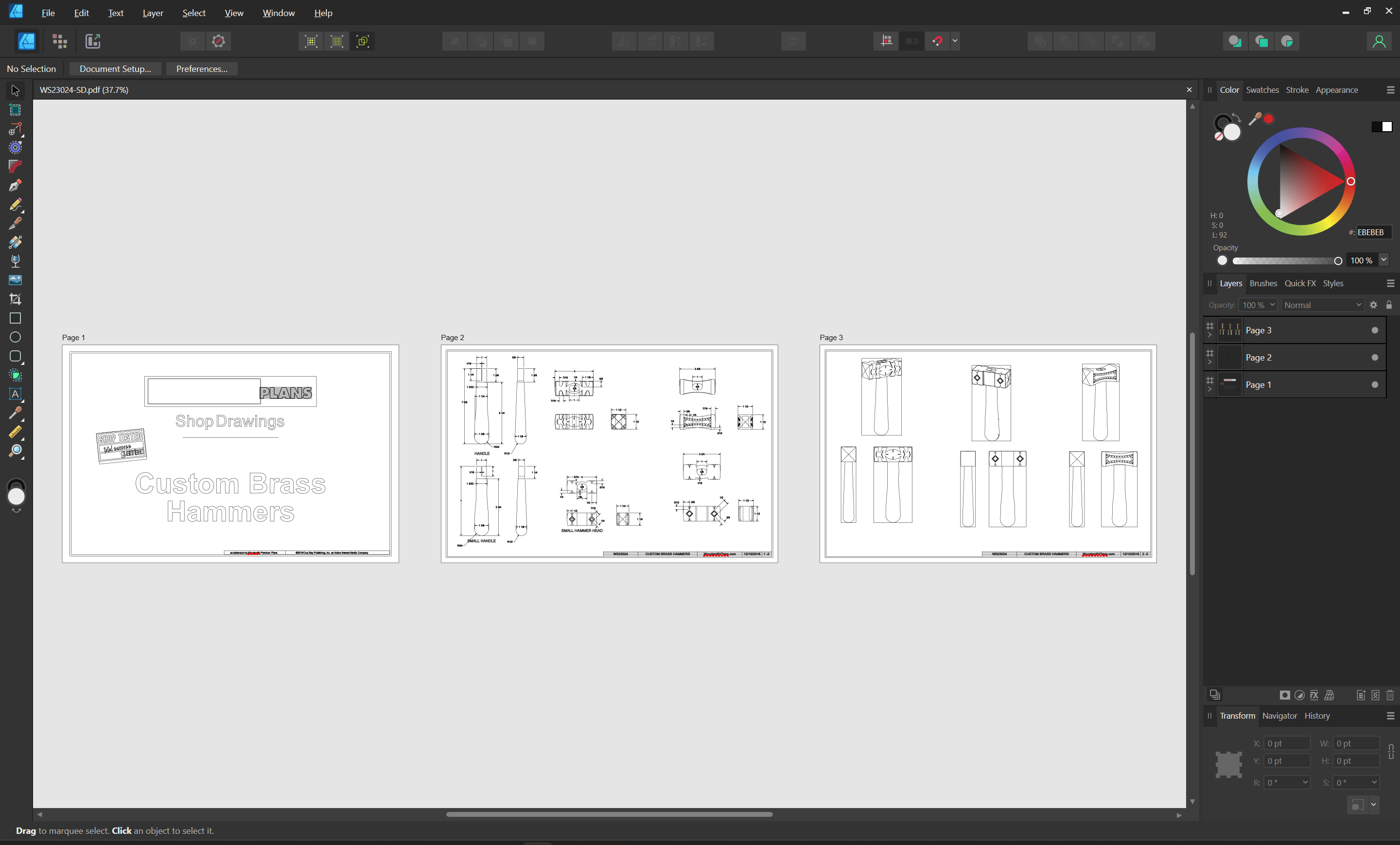
First, one buys the plans, then, one imports them into a program which will import the PDF as vectors:
and then export the desired hammer design as an outline — or one can re-draw it by scanning a printout and putting it on the background to re-draw, or by using Image Tracing:
We just posted CC 520 to: https://carbide3d.com/carbidecreate/download/
520 includes a big new feature for us, Image Tracing.
[image]
You should be able to load a JPG or PNG and get a reasonable set of curves from it very quickly.
A few caveats:
Right now, it’s mono only so color images will be converted to black and white using the thresholds in the window.
We’re not optimizing for very small images so some will work well, others won’t. We’d recommend images larger than 500px on a side …
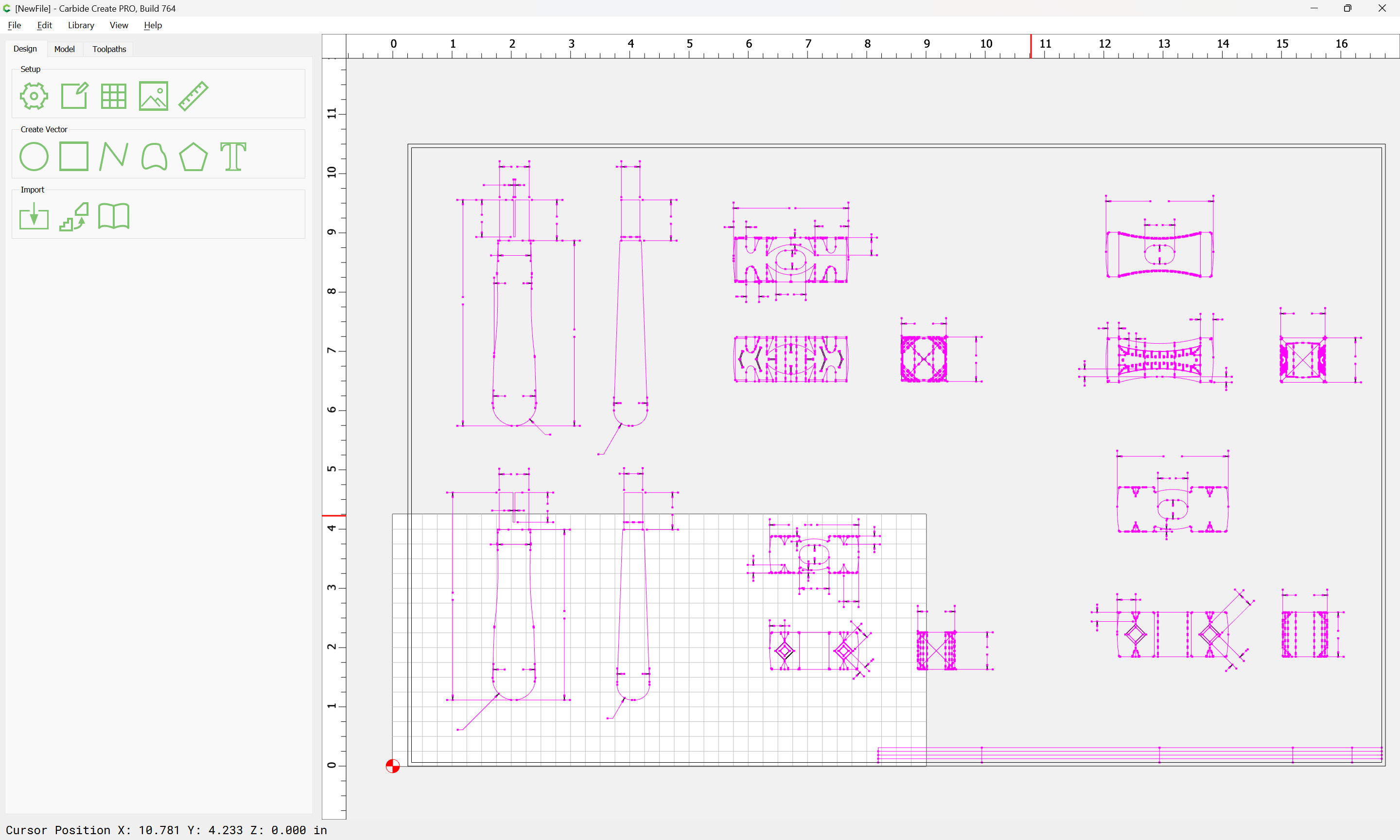
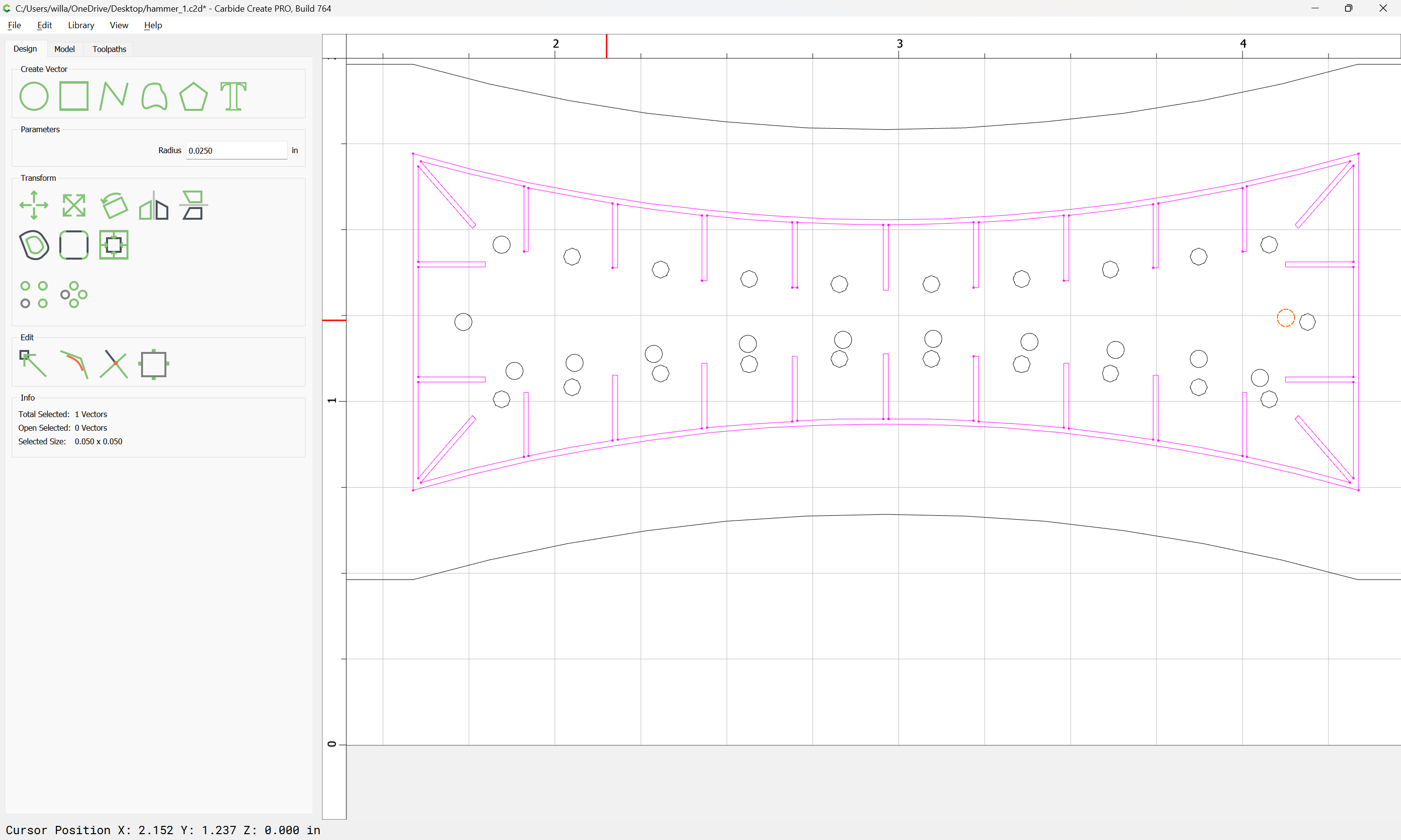
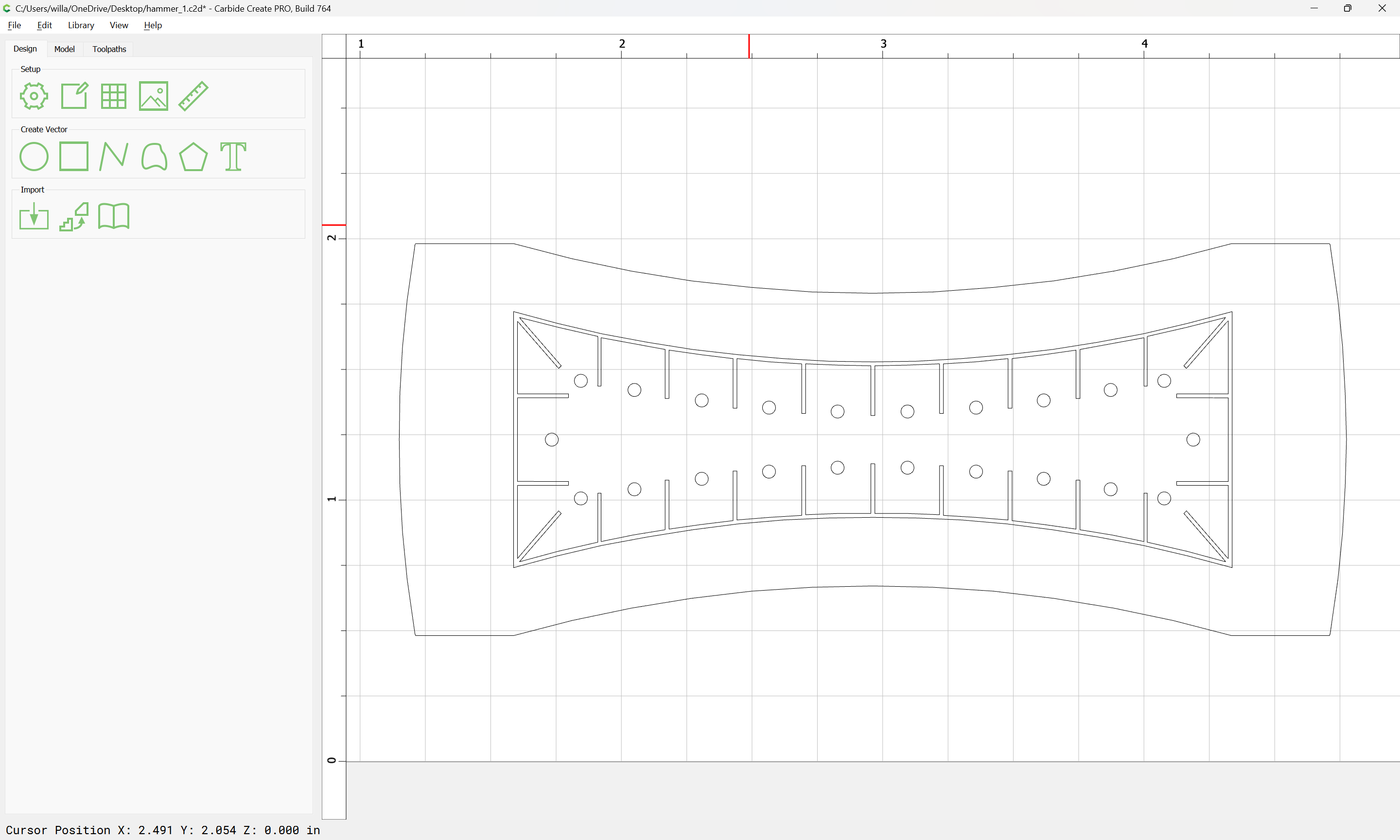
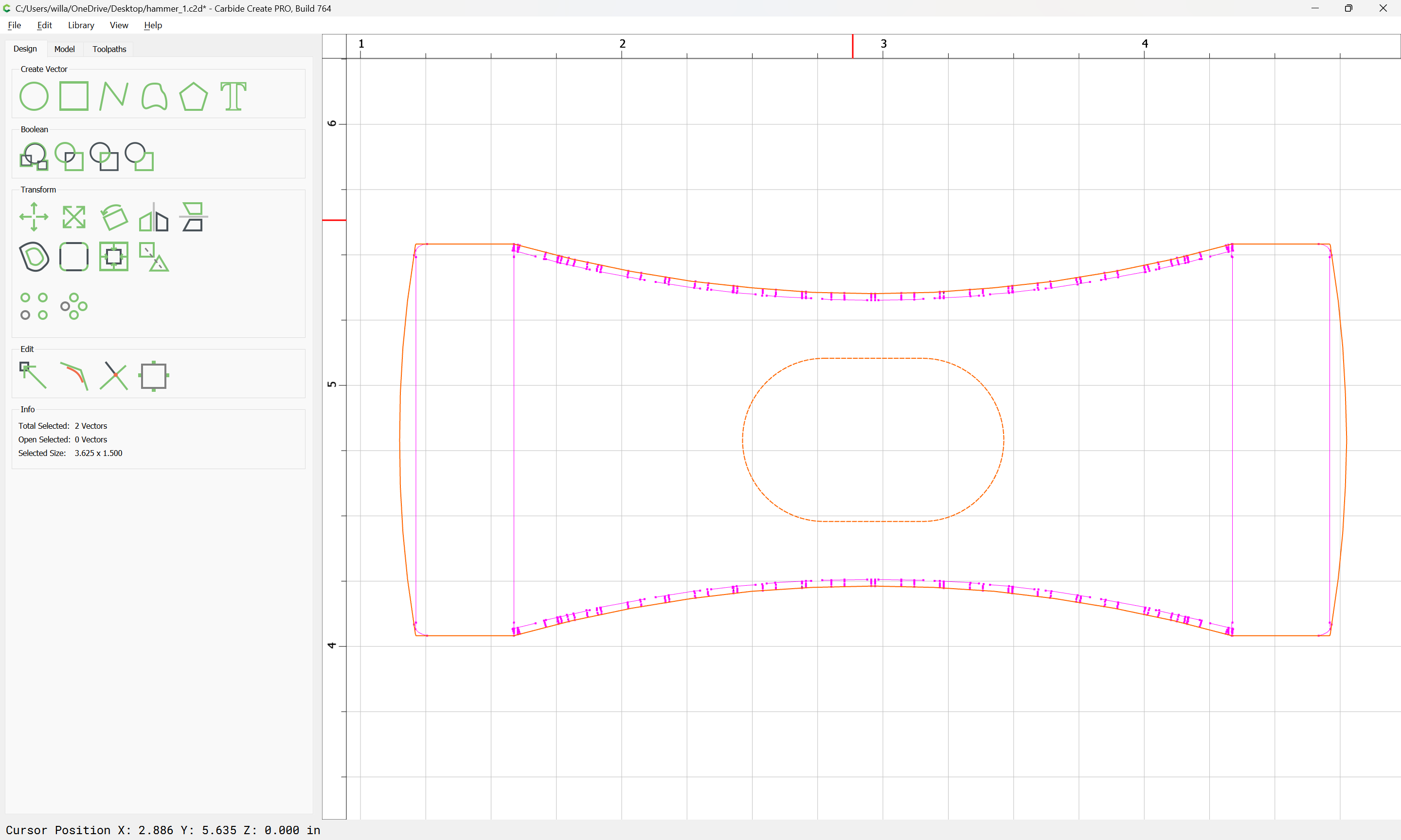
Once one has the vectors in Carbide Create:
It will be necessary to pick a design and begin joining the vectors (that they appear magenta is caused by their not being closed) and then using said vectors to model the design.
WillAdams
February 2, 2024, 10:30pm
2
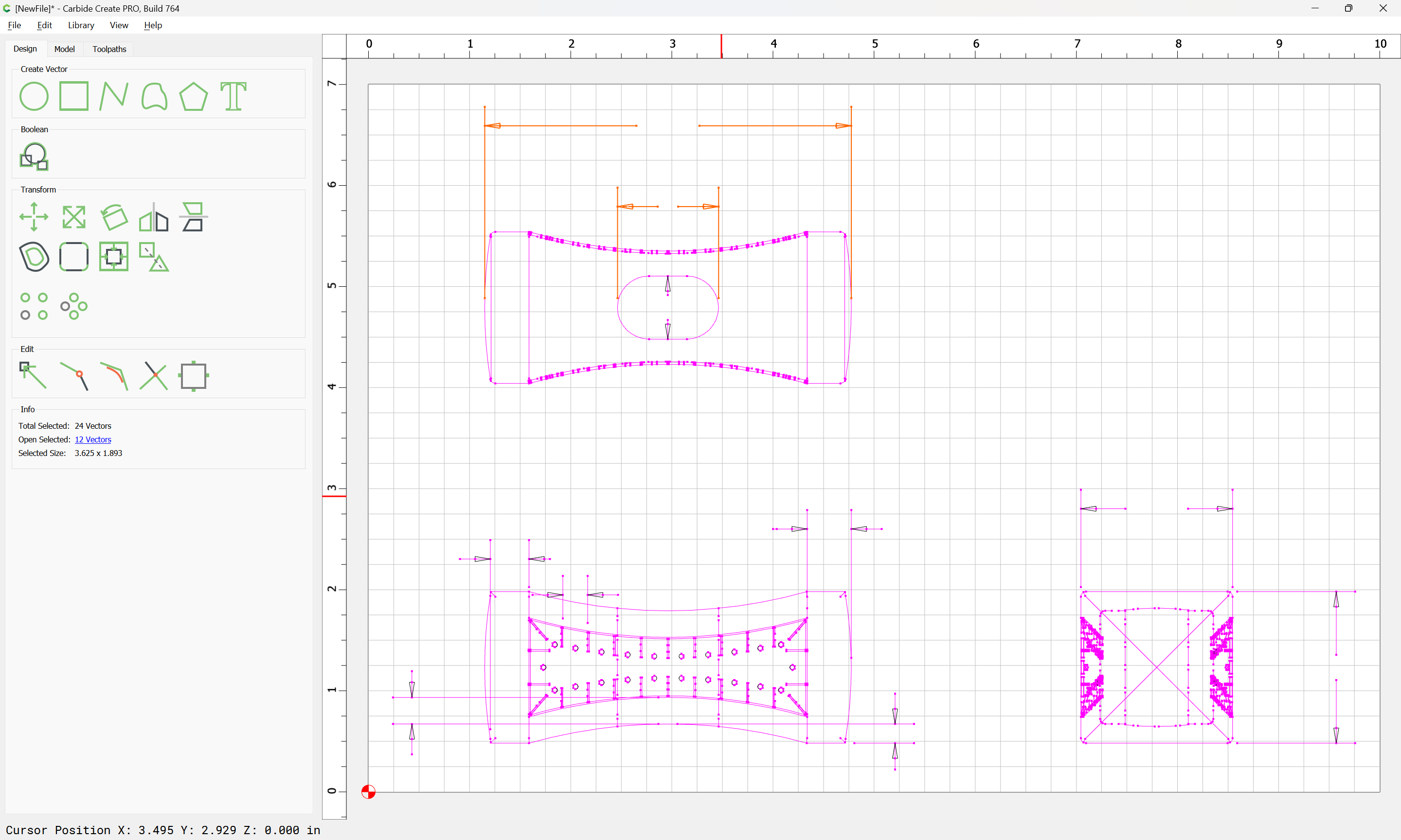
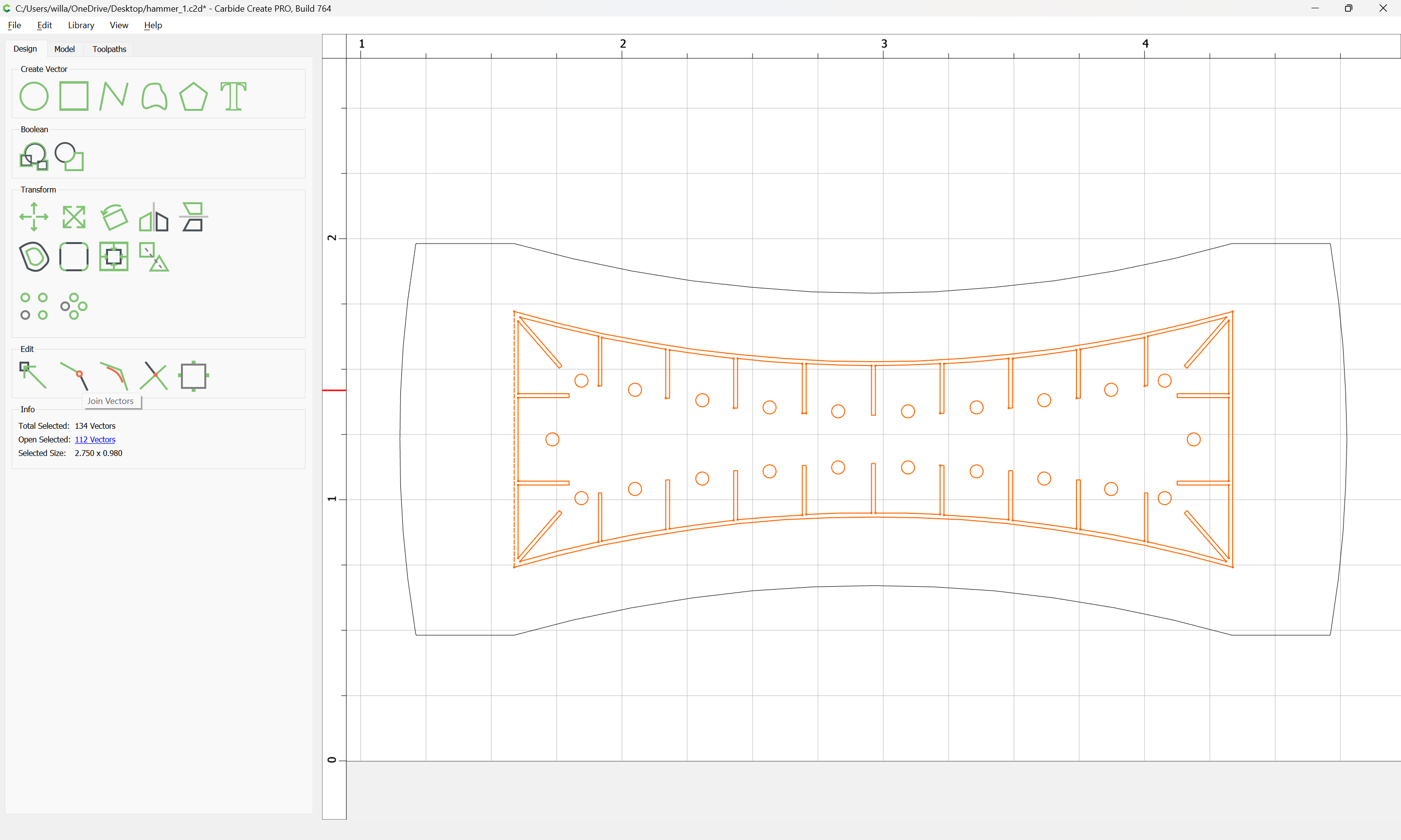
We pick one of the designs and isolate it, and scale it up to actual size (the drawings seem to be 50%).
create a new layer and move dimension lines and so forth out:
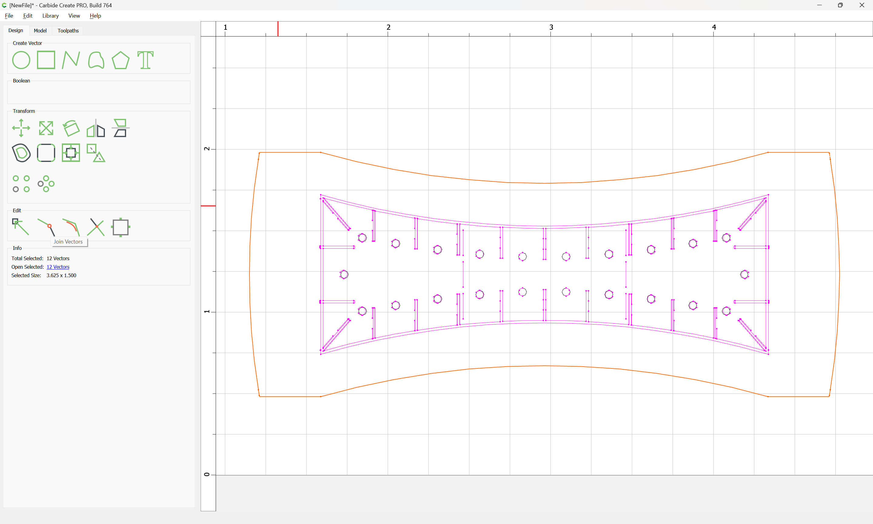
and select isolated geometry:
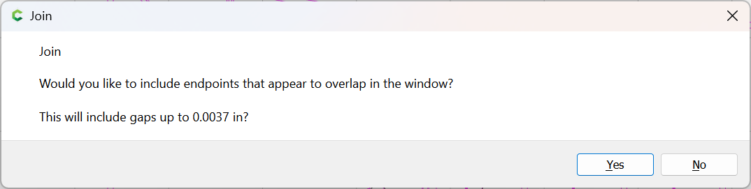
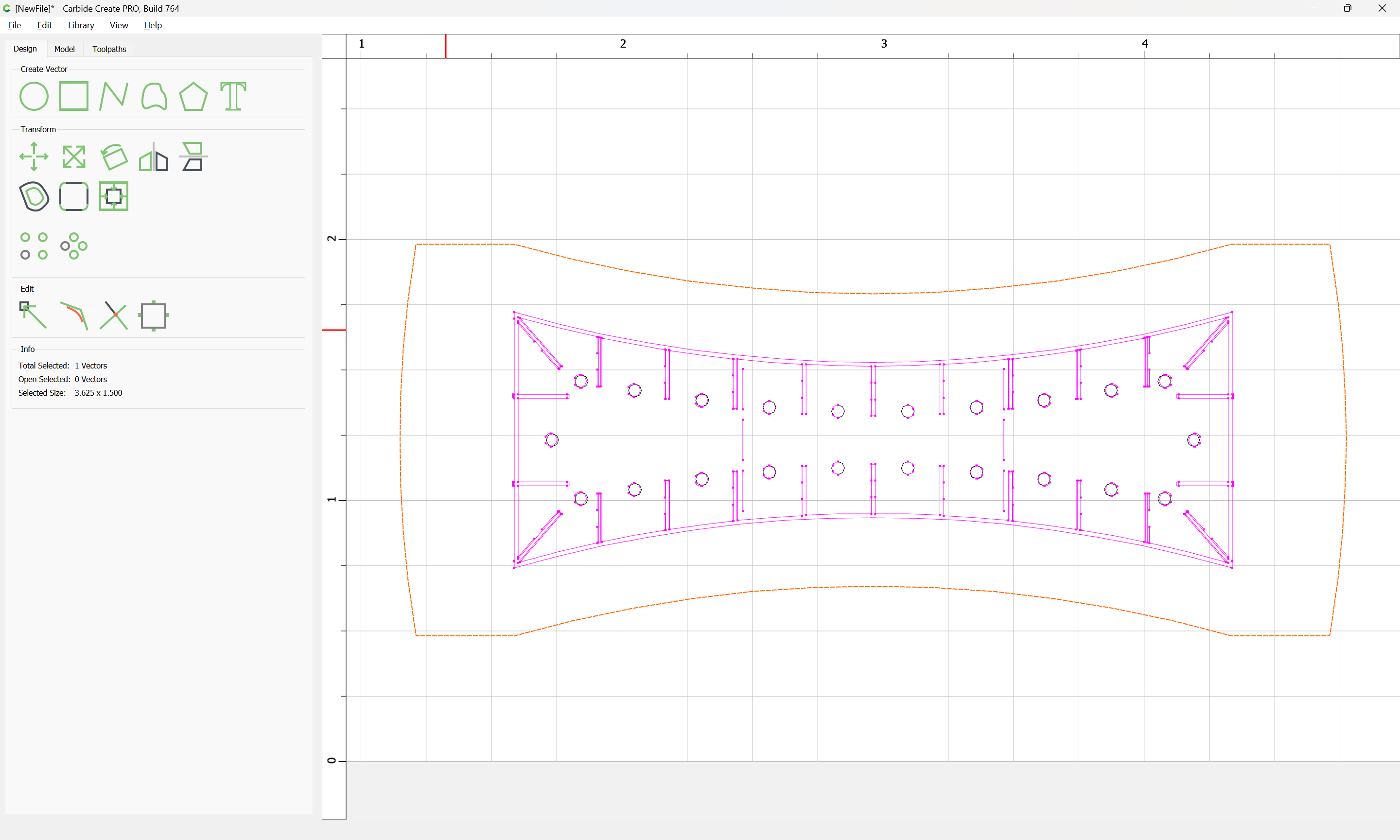
and use Join Vectors:
Yes
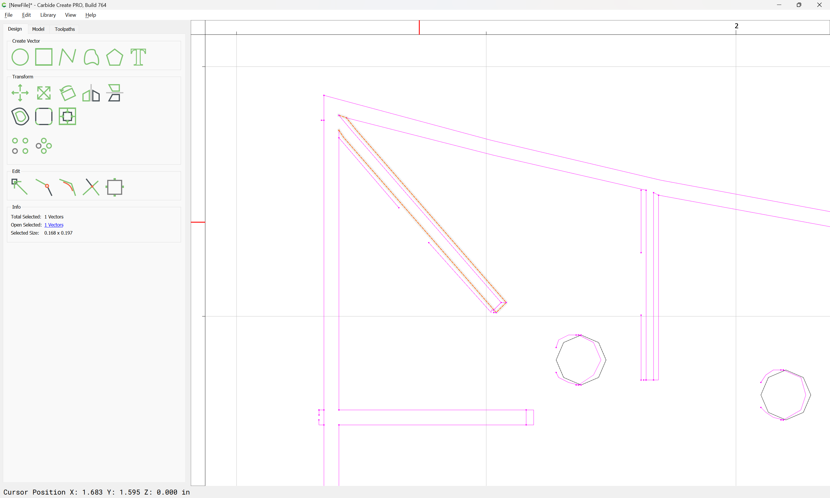
For the decorative design, zoom in and remove extraneous geometry:
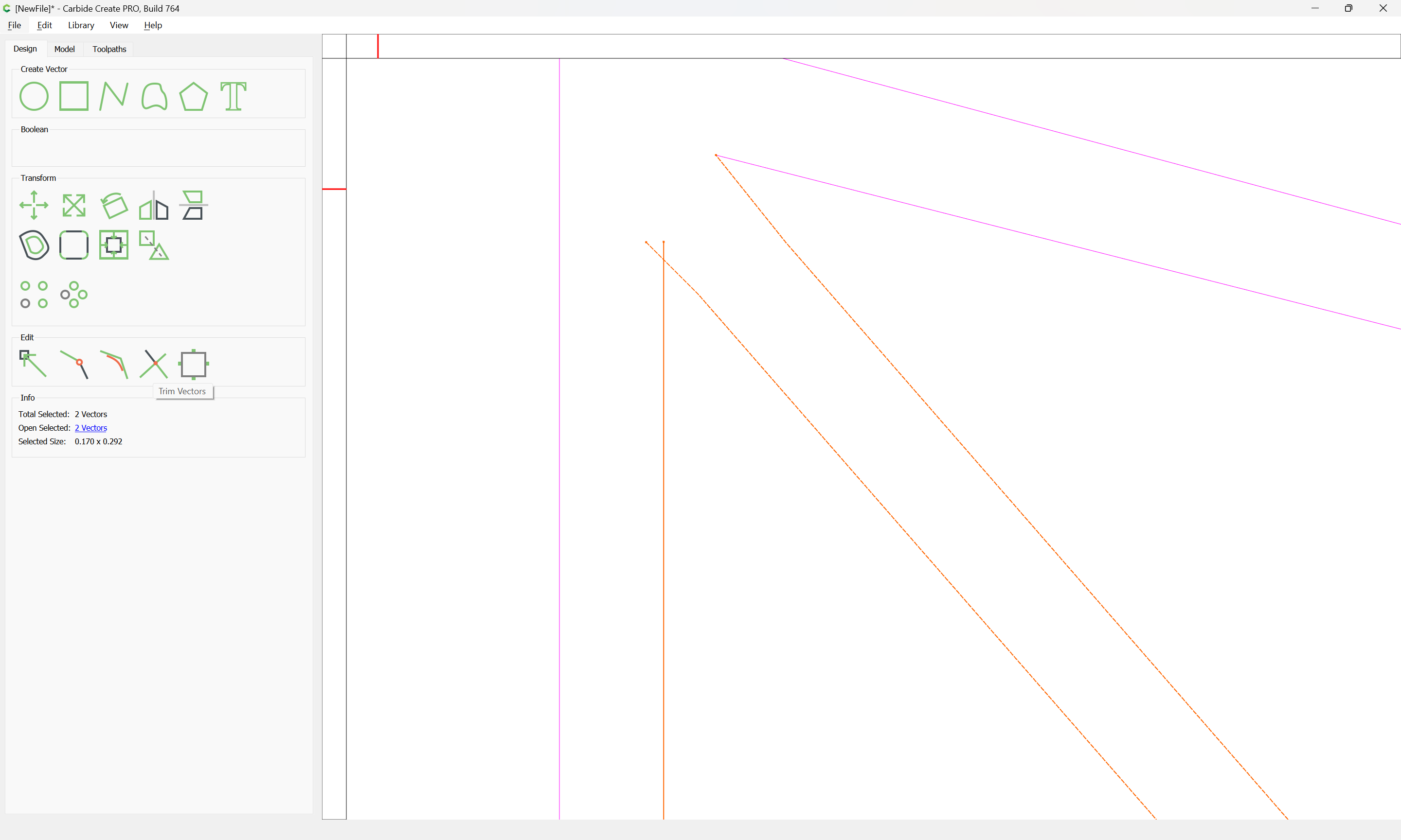
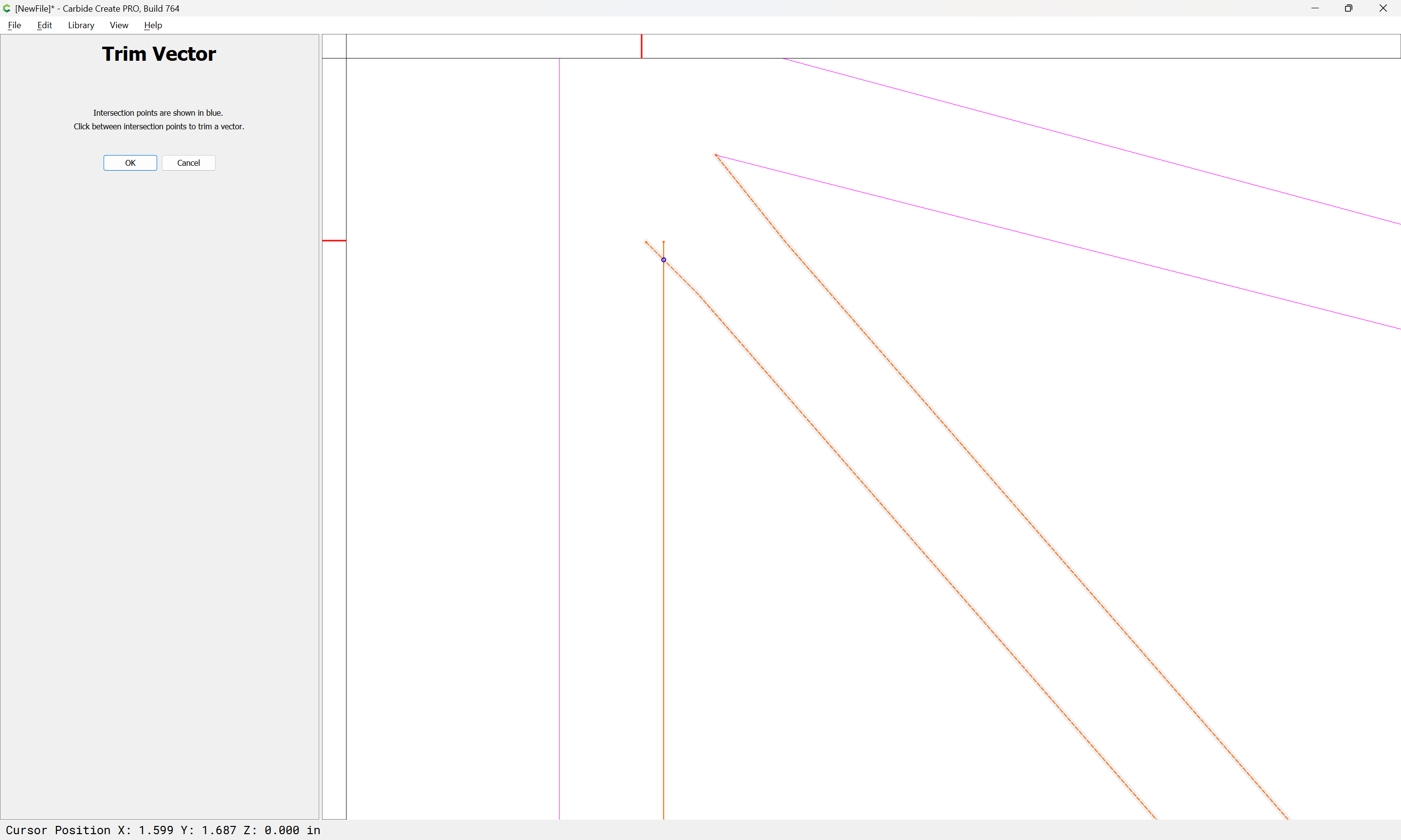
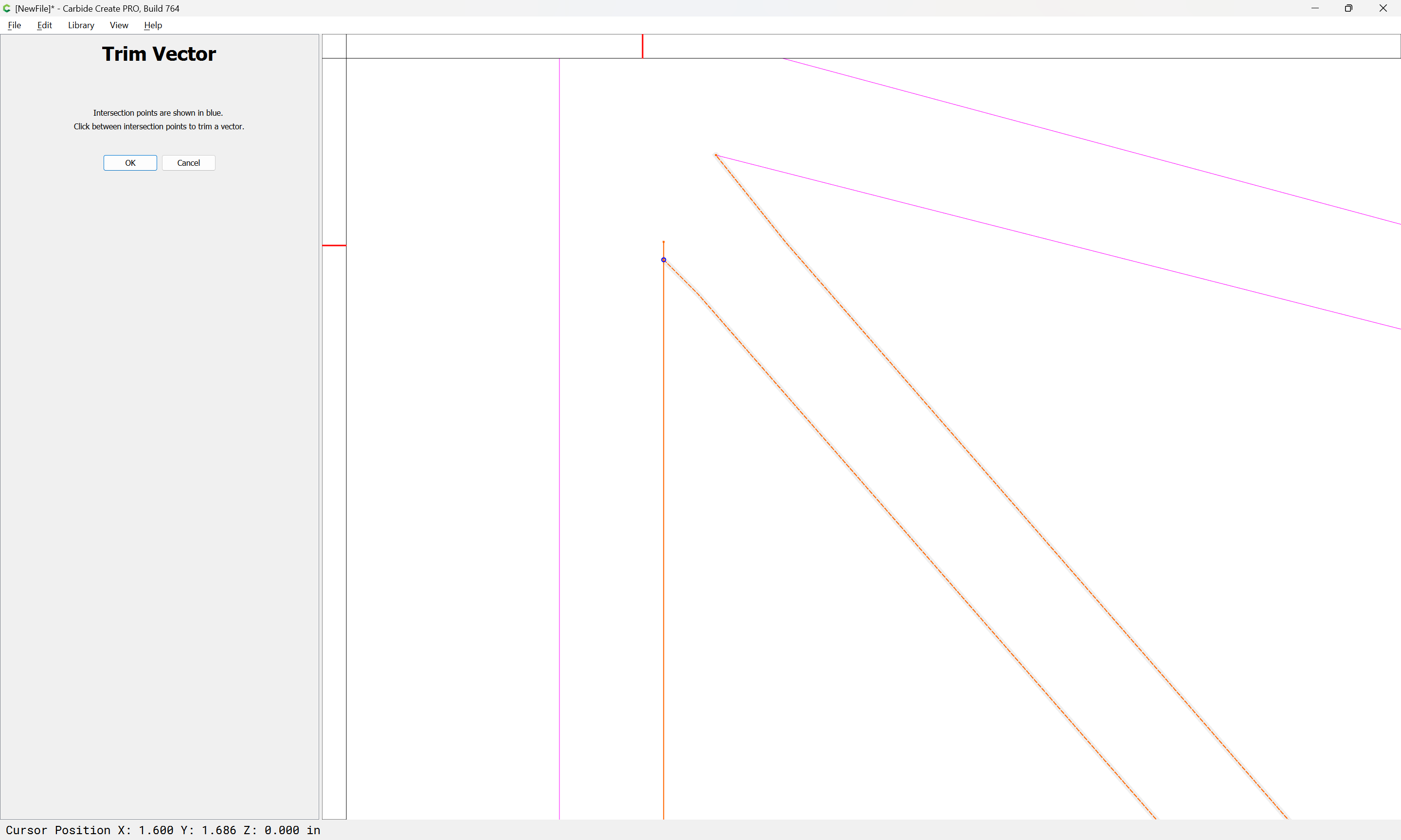
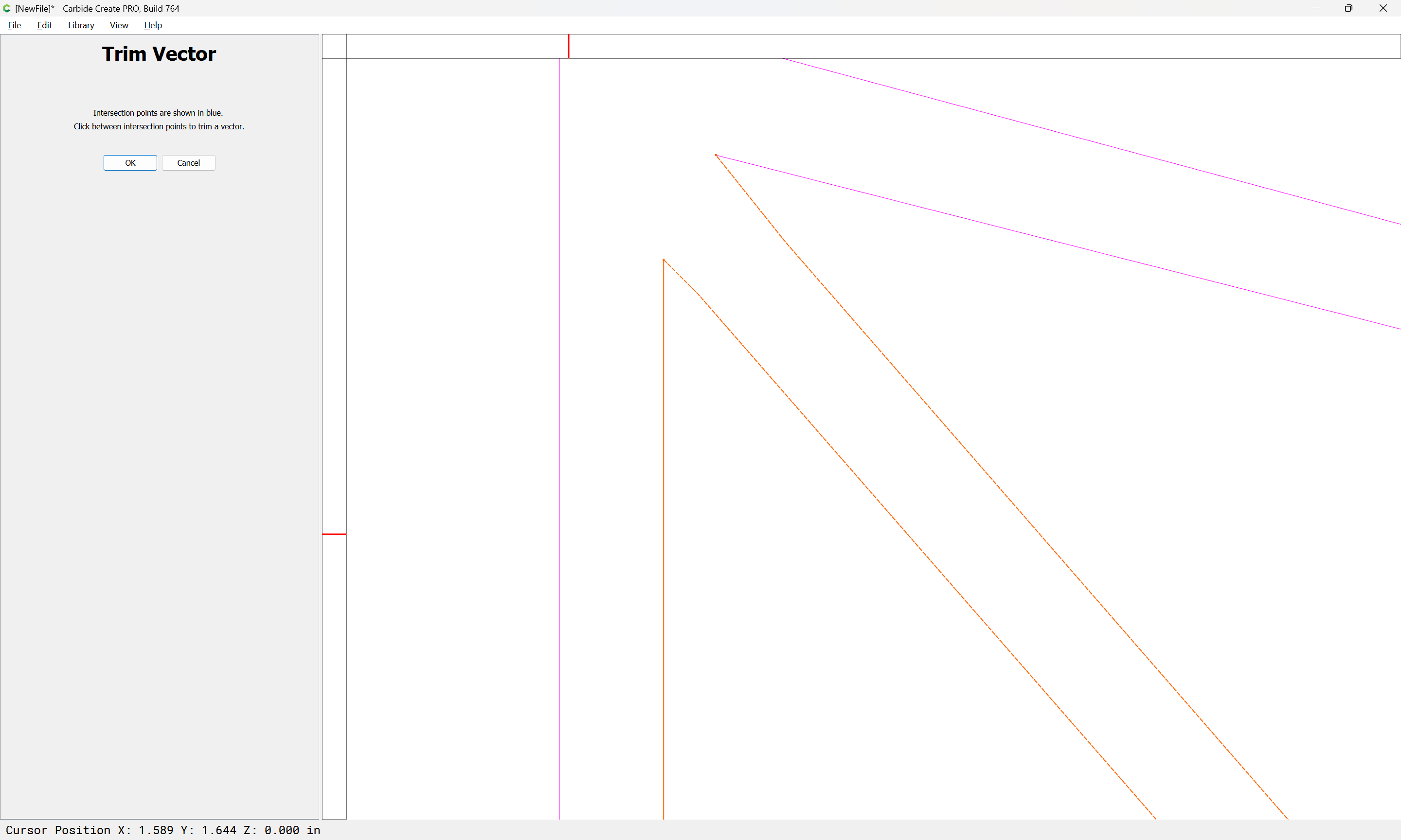
and where necessary, select overlapping geometry and use Trim Vectors:
to remove unwanted segments:
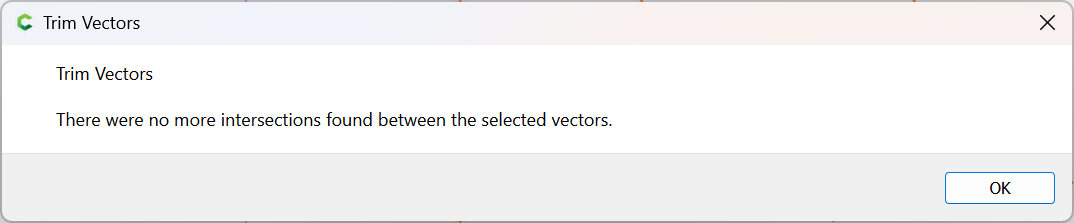
OK
OK
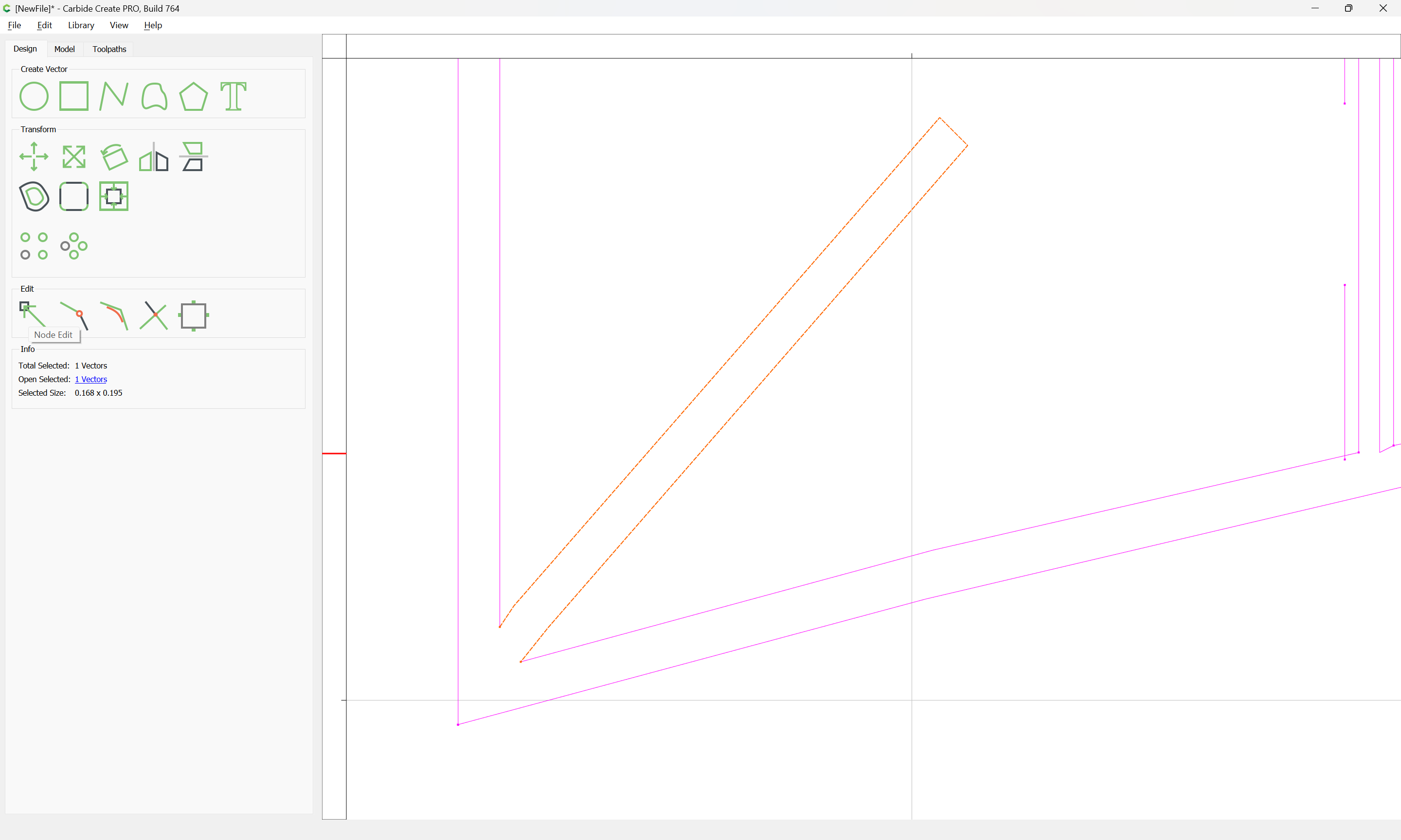
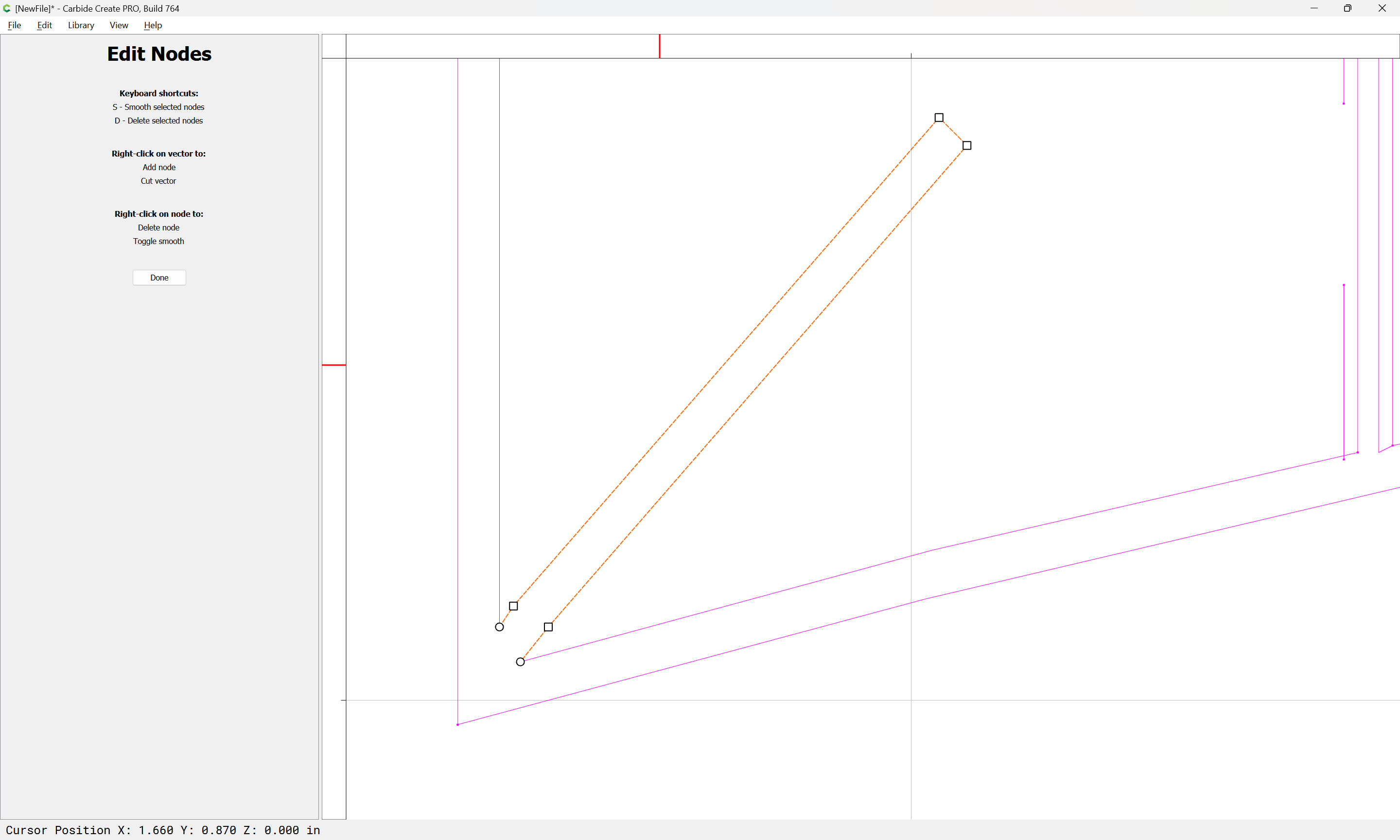
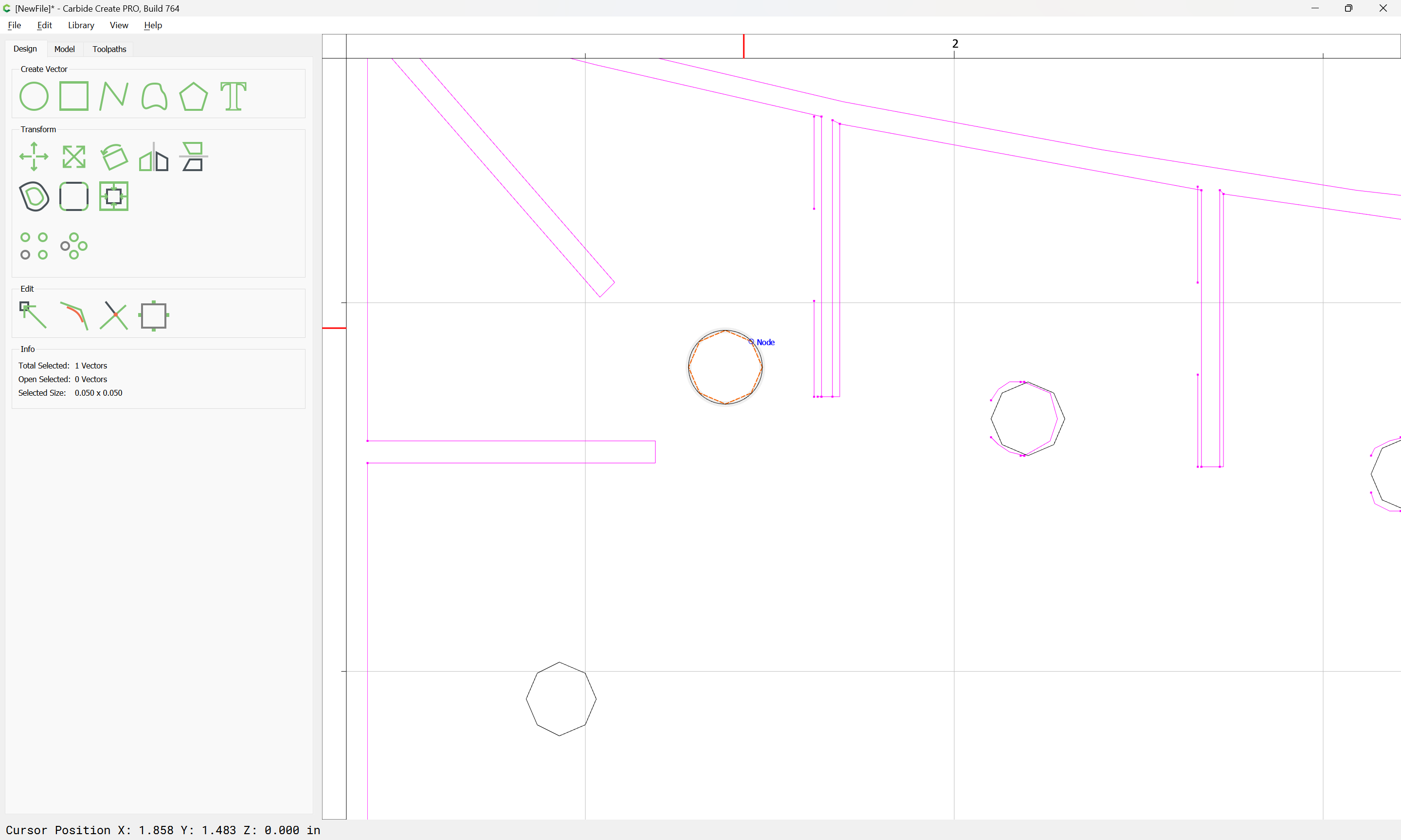
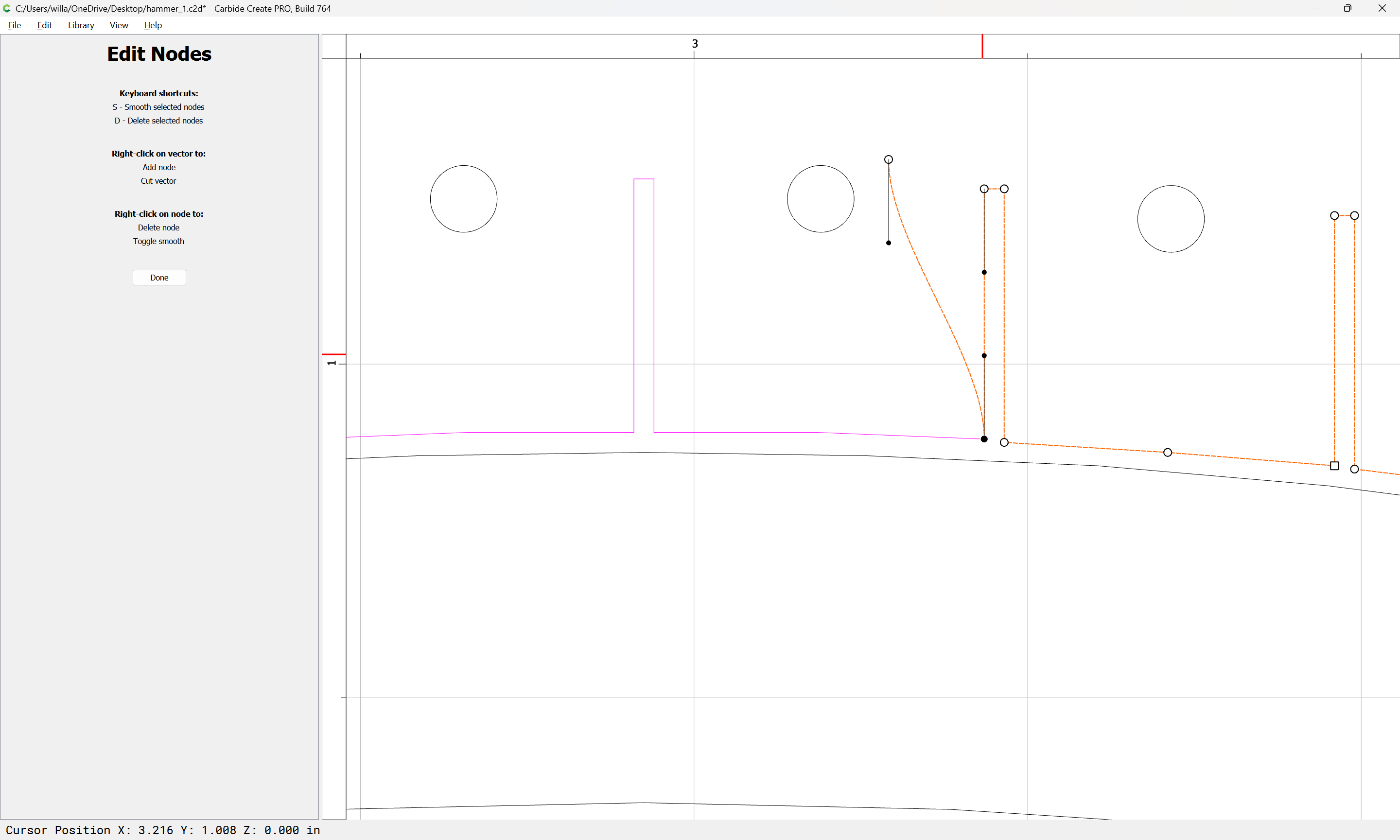
Where appropriate, go into Node Edit mode:
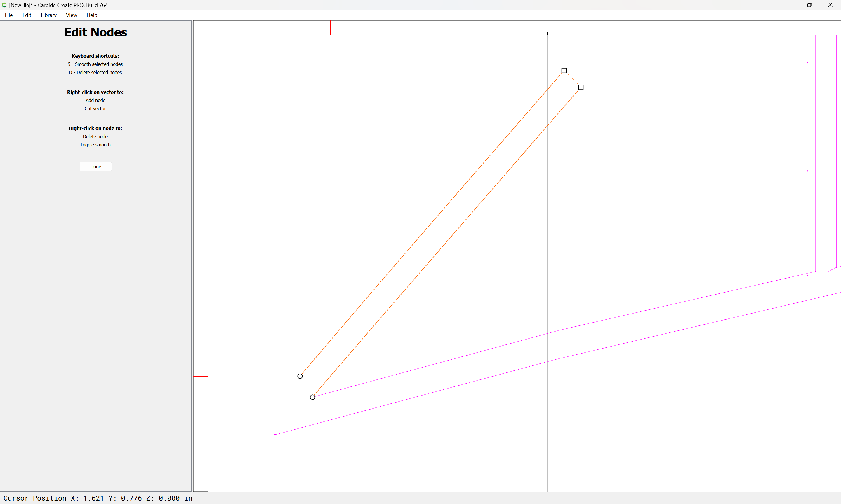
and select extraneous nodes and delete them to straighten things out:
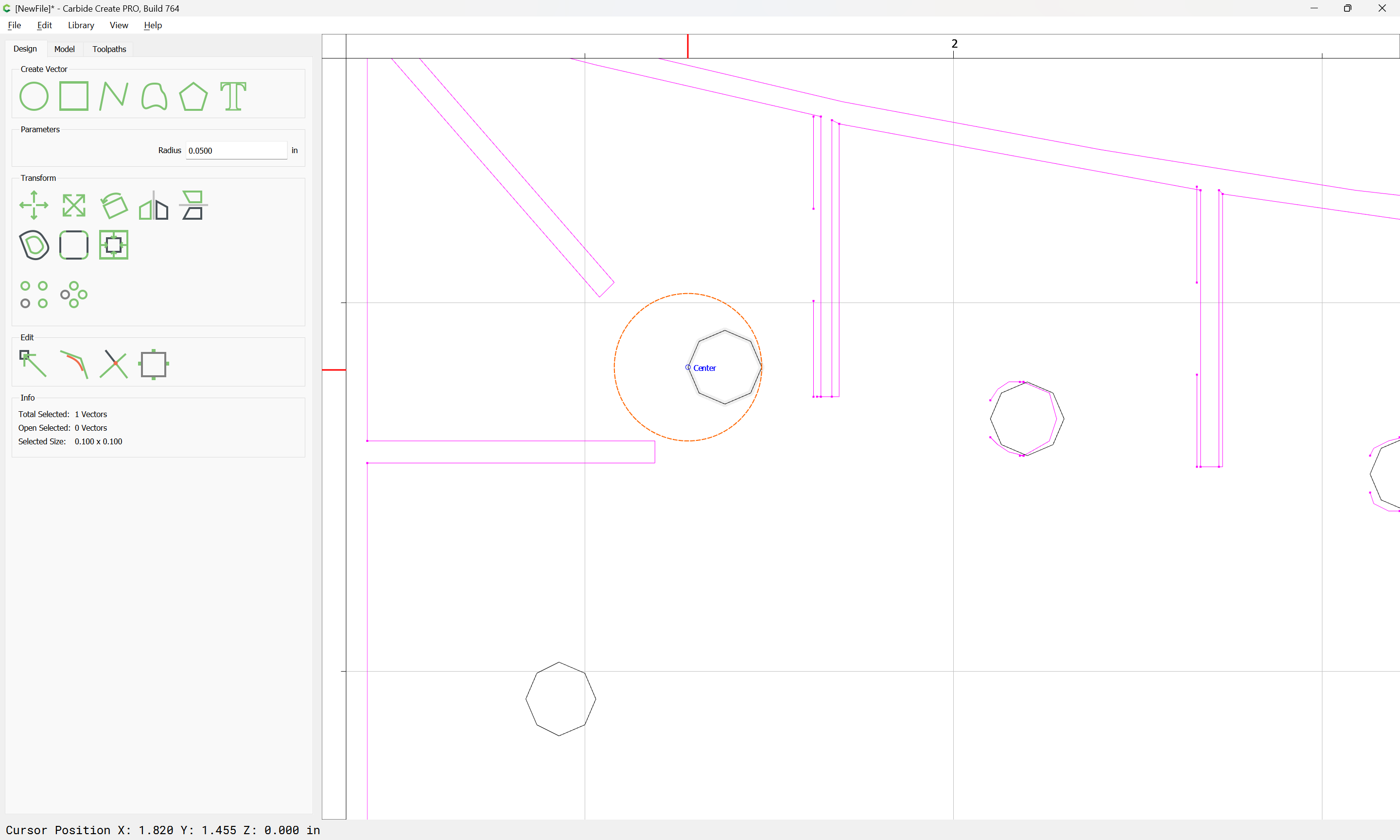
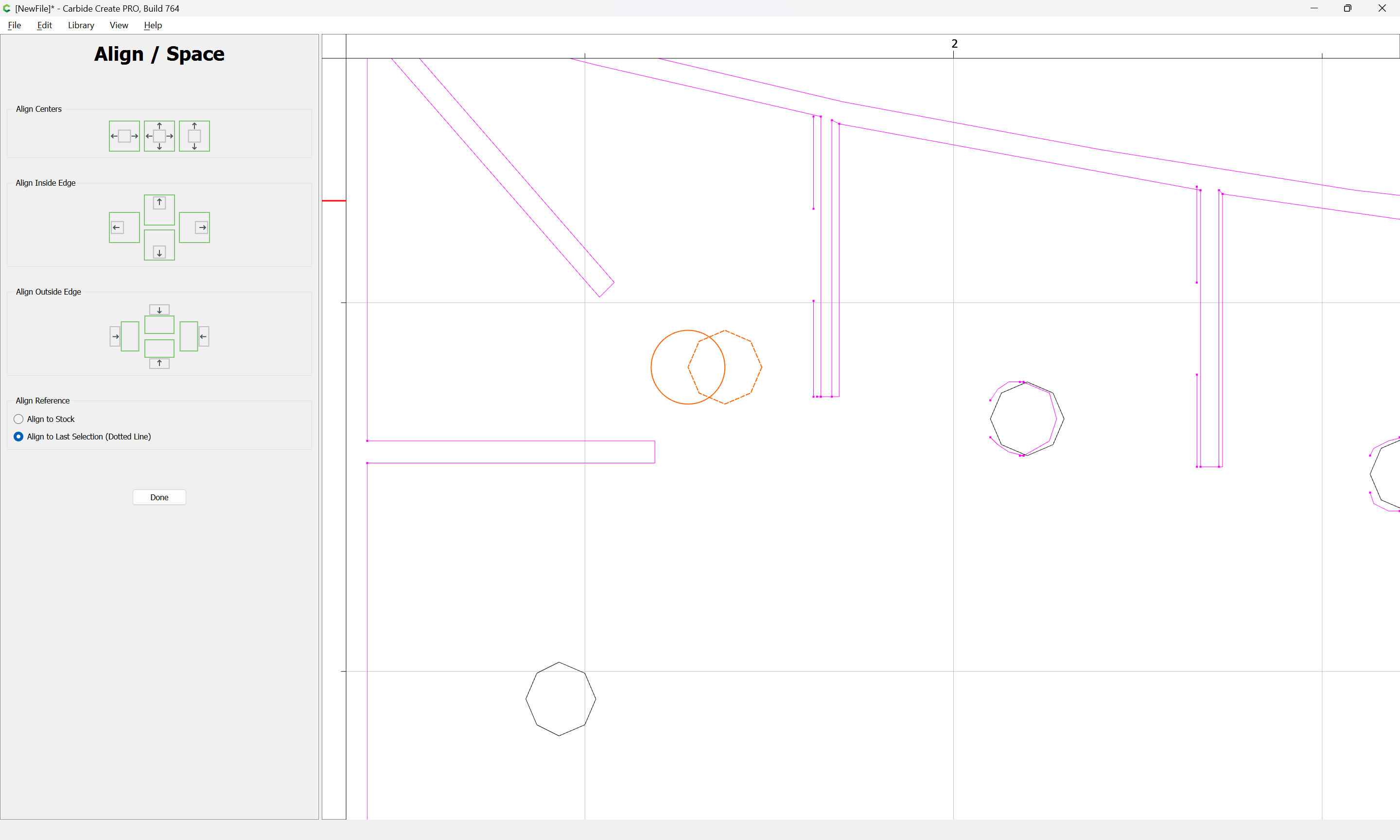
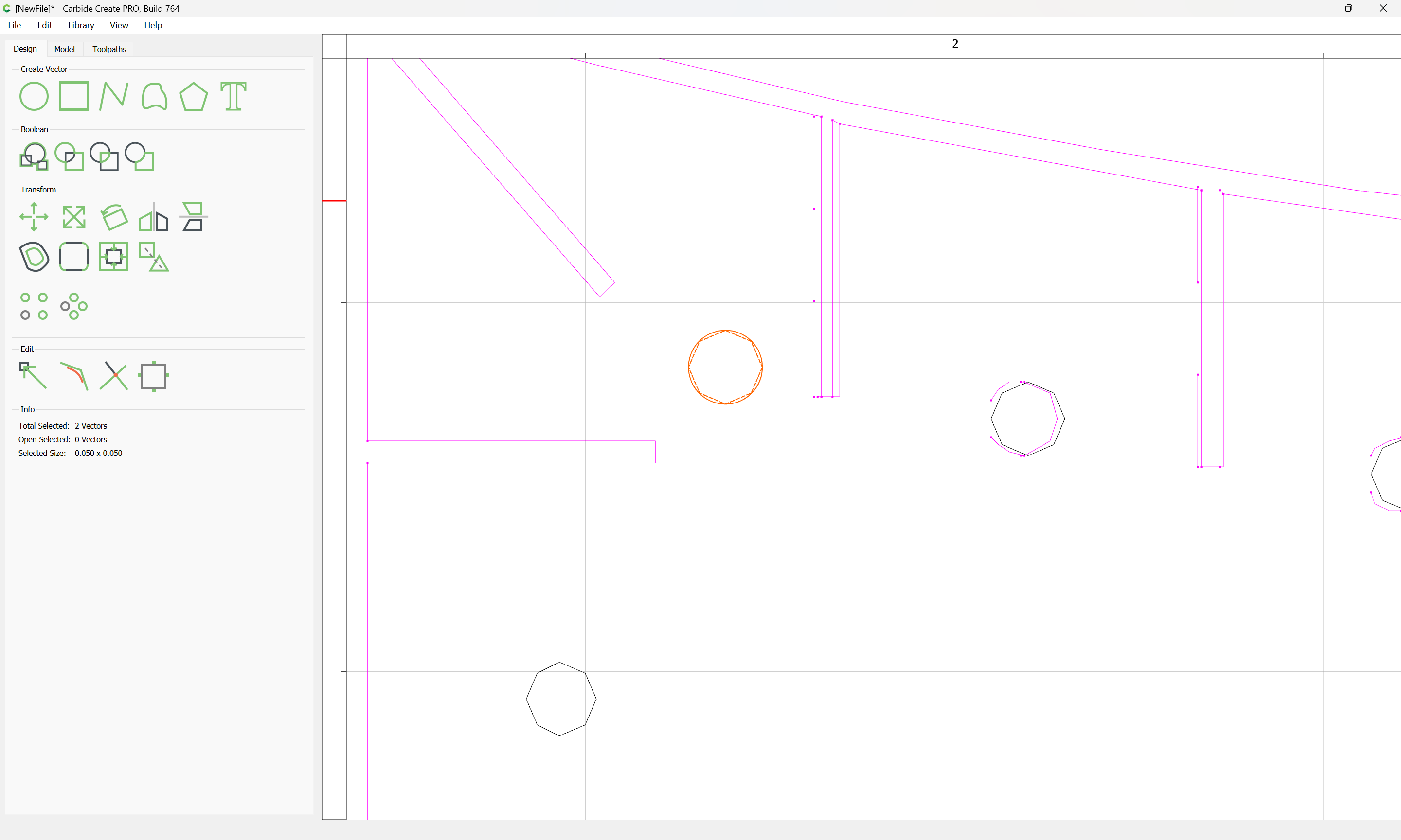
Where necessary, draw in circles using polygons as guides:
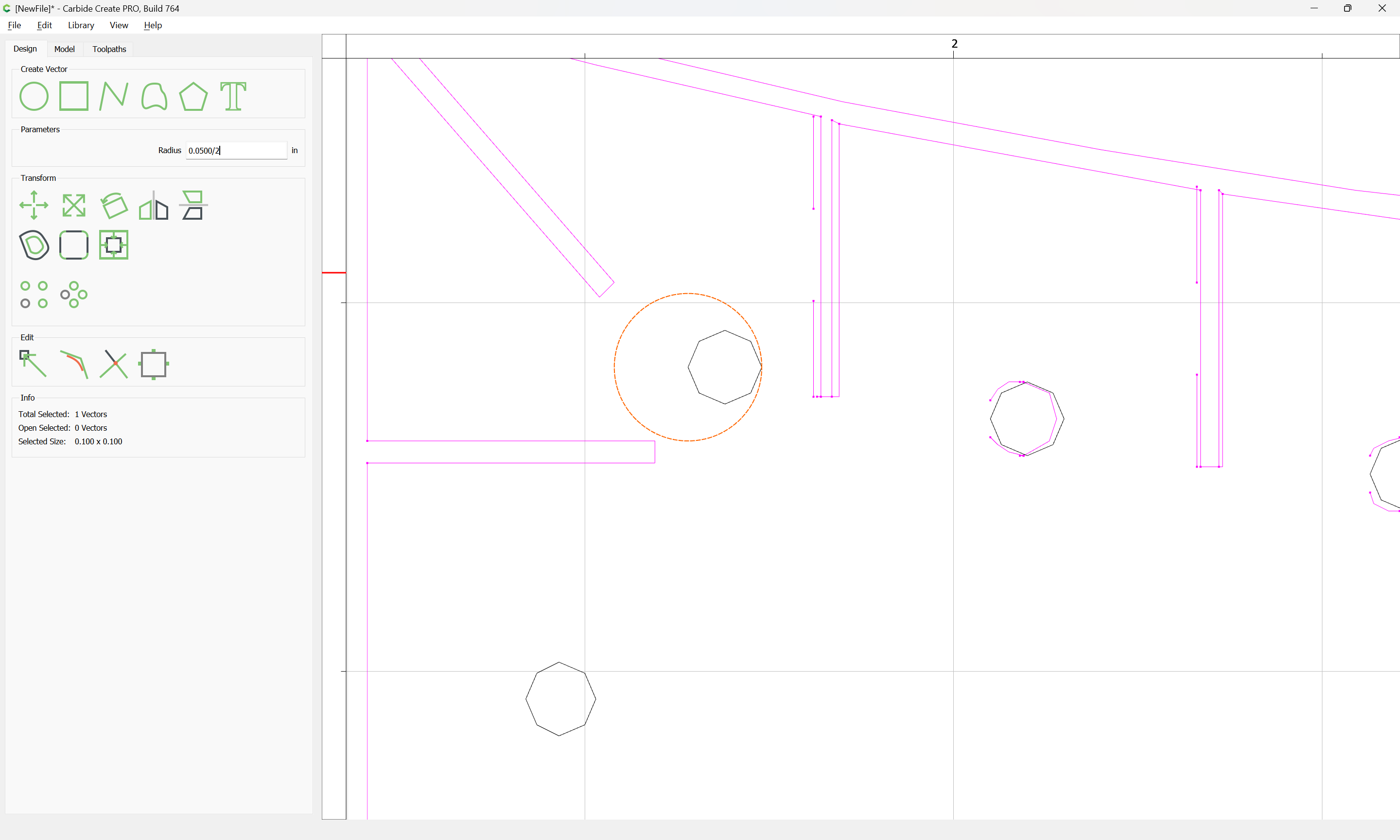
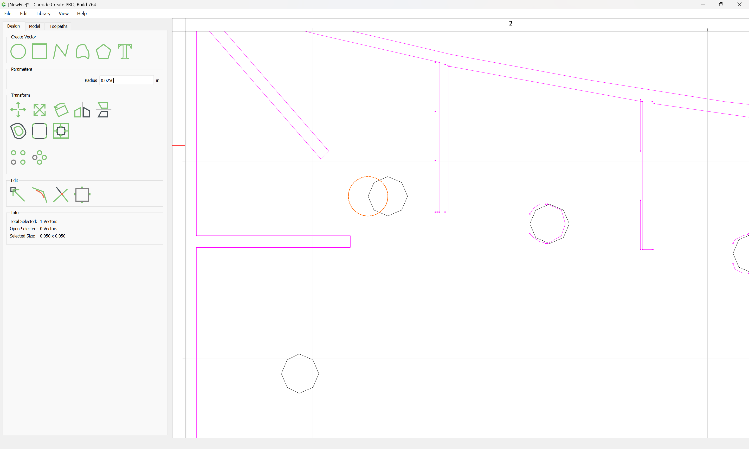
and then scale them down to 50% of their size:
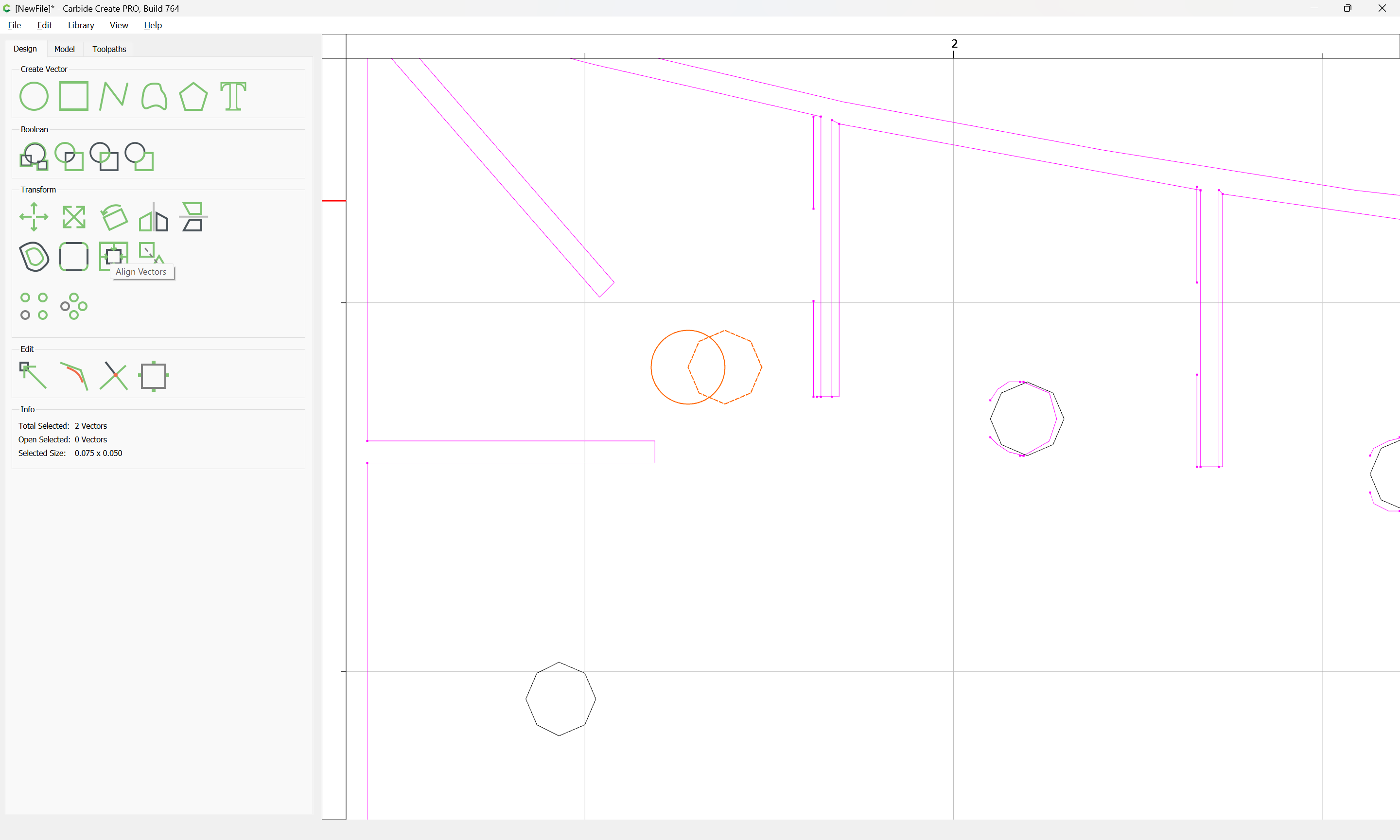
and align them with the originals:
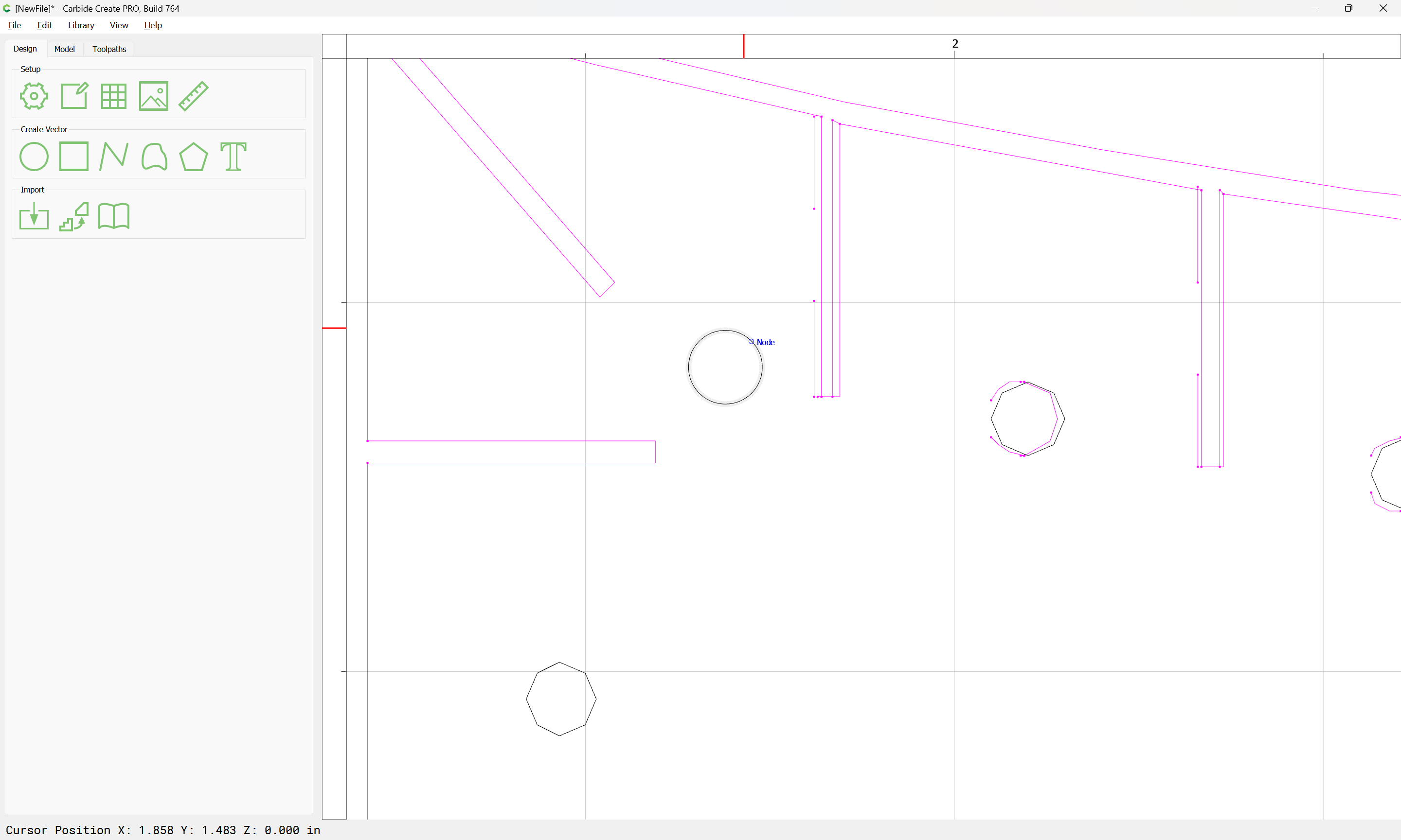
and delete the original:
Repeating as need be.
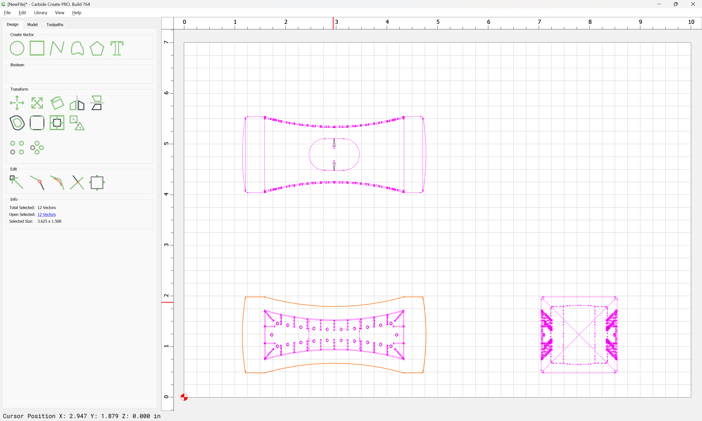
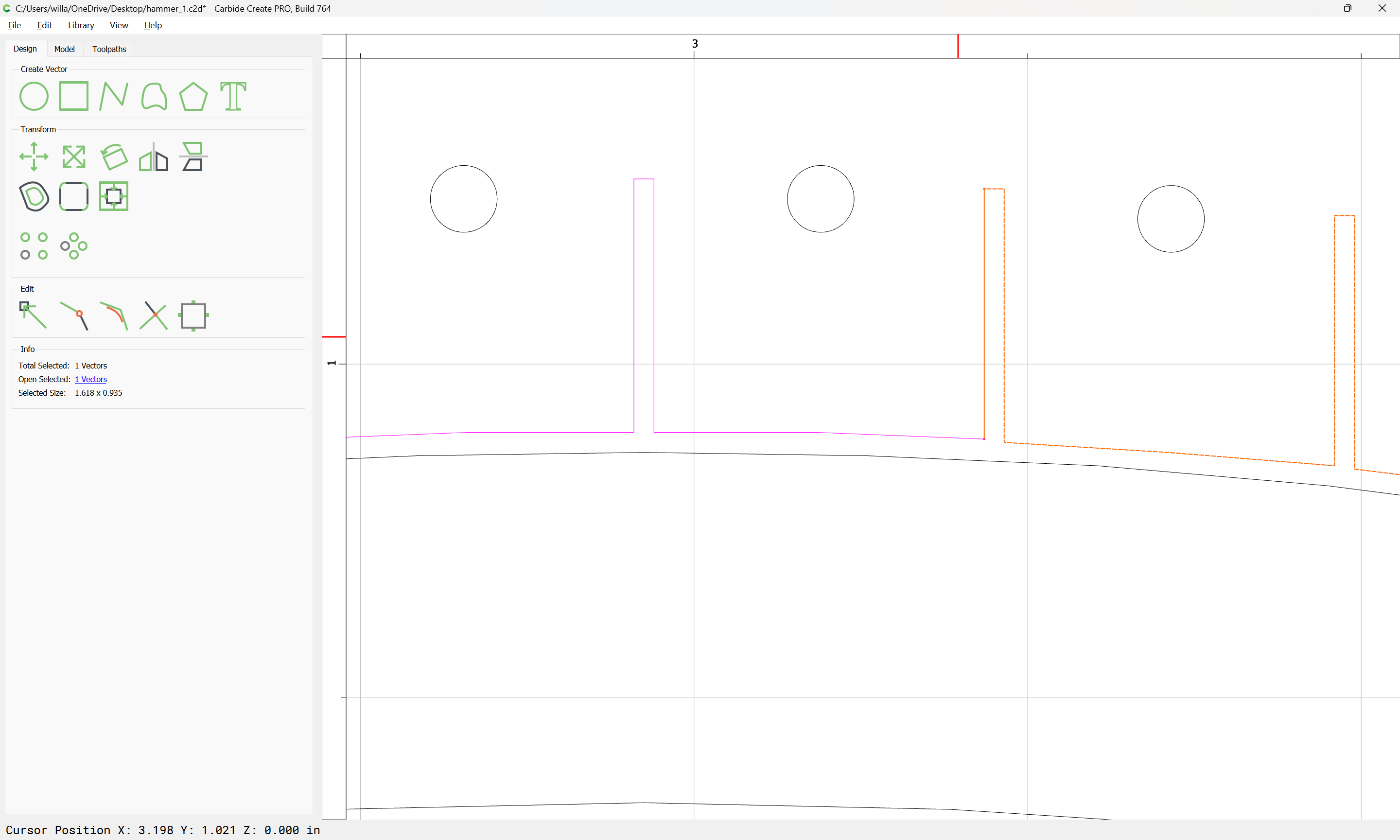
until one arrives at geometry which may be joined to close:
Investigate where things don’t match:
and remove extraneous lengths:
WillAdams
February 2, 2024, 11:01pm
3
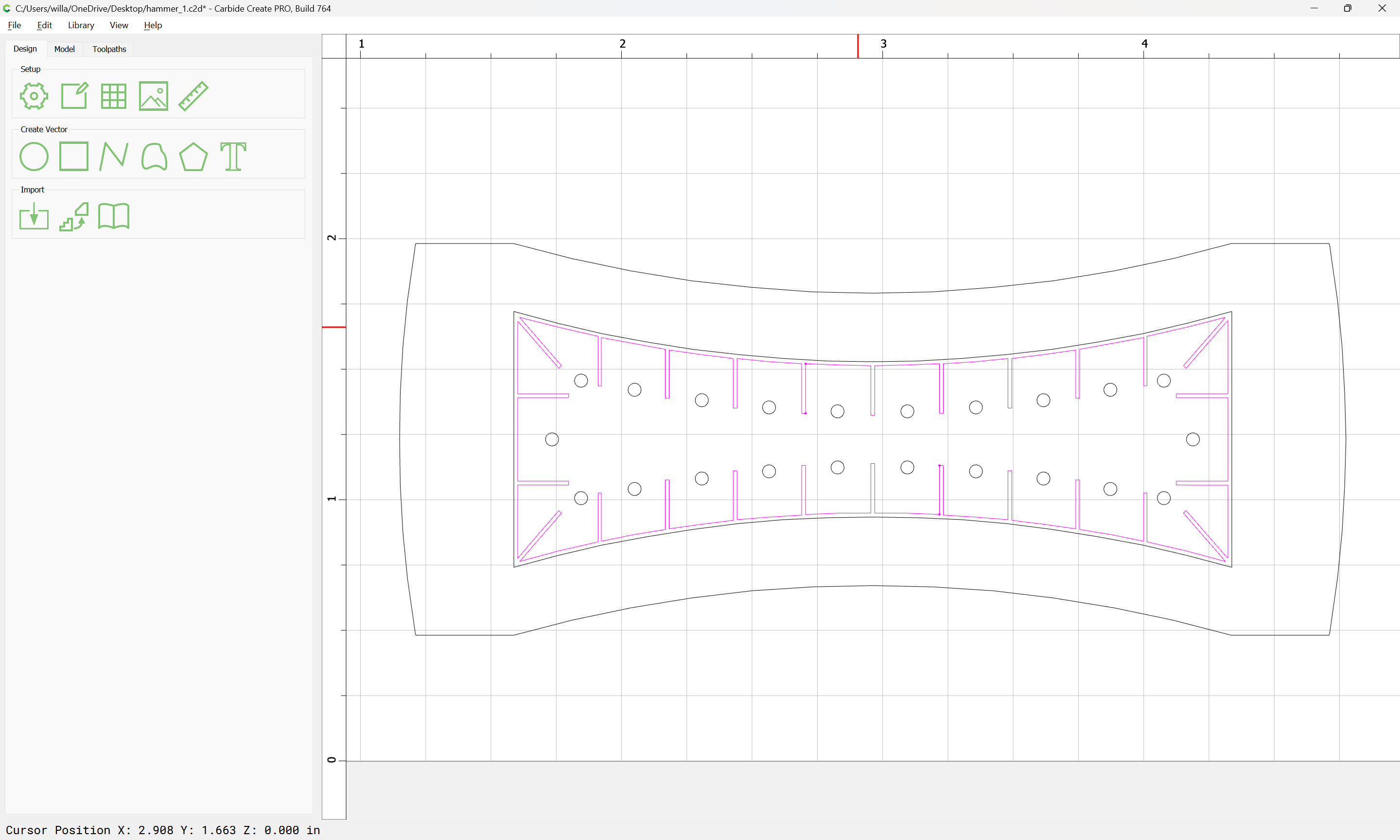
Eventually arriving at:
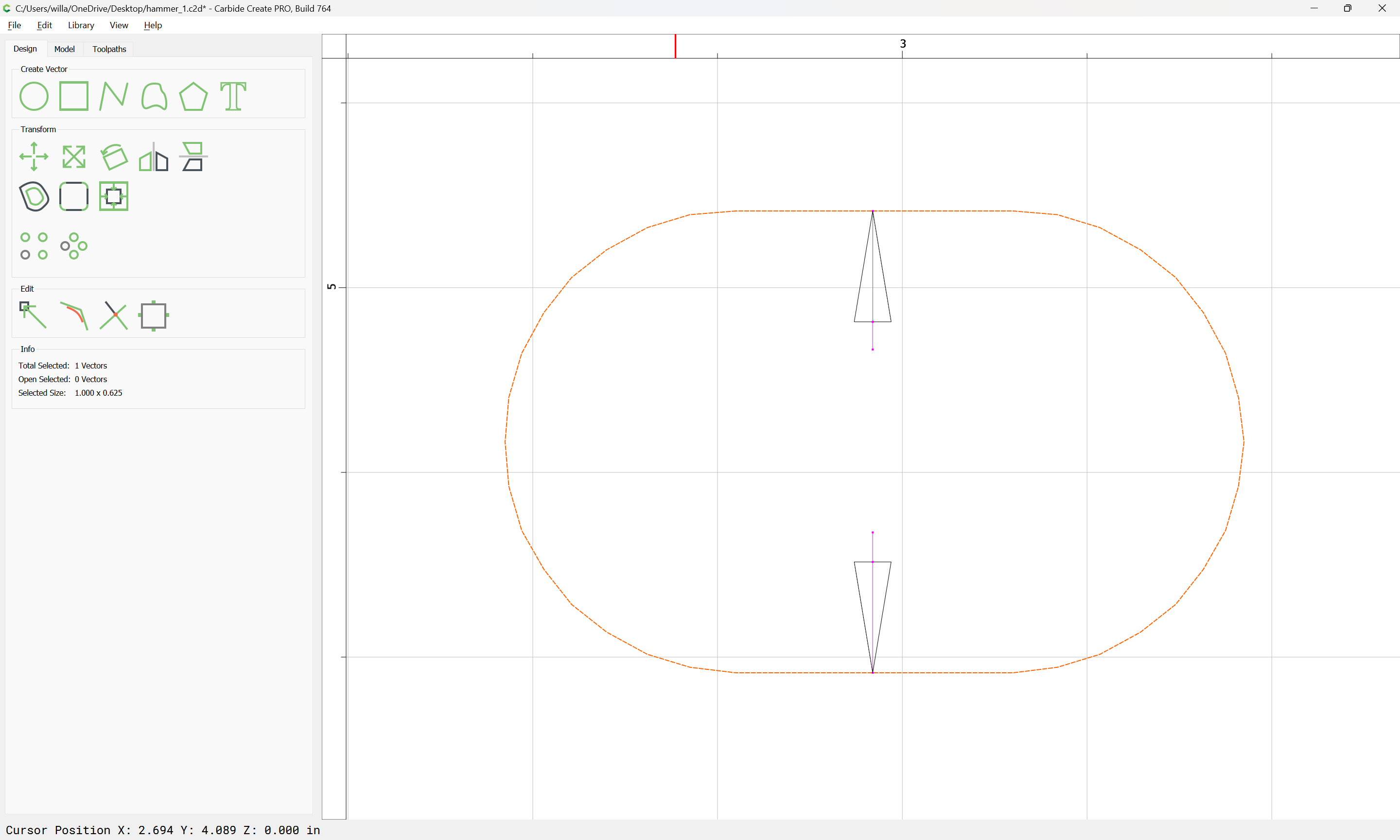
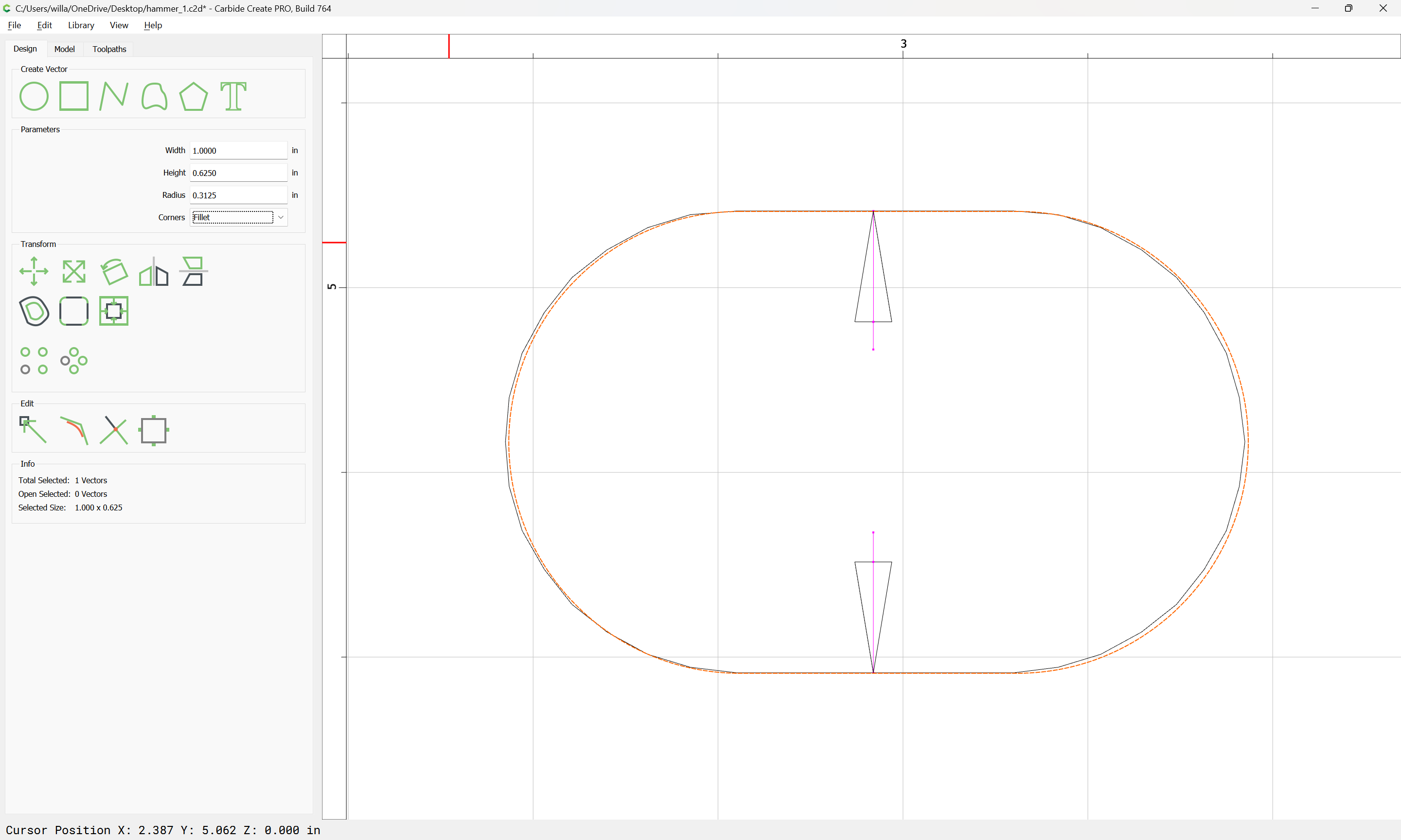
The hole for the handle is suitable to re-create:
Yielding a smoother feature.
For the top view, there is a slight difference in the outline, but this will not be preserved (doing so is left as an exercise for the reader).
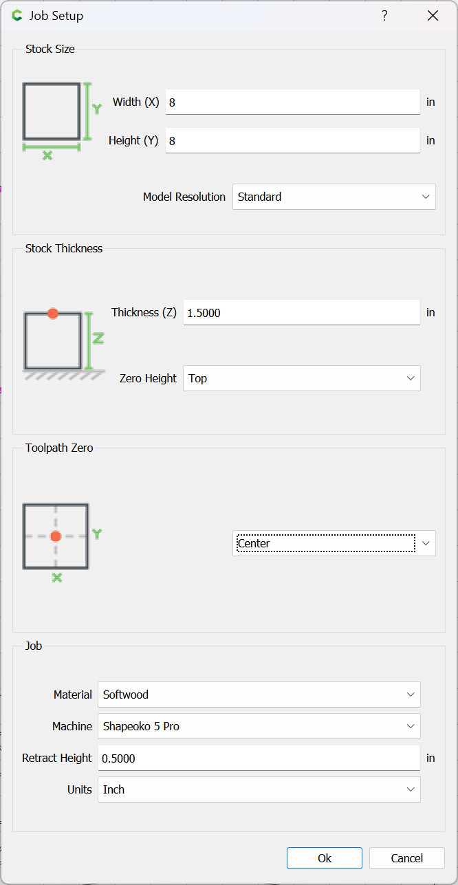
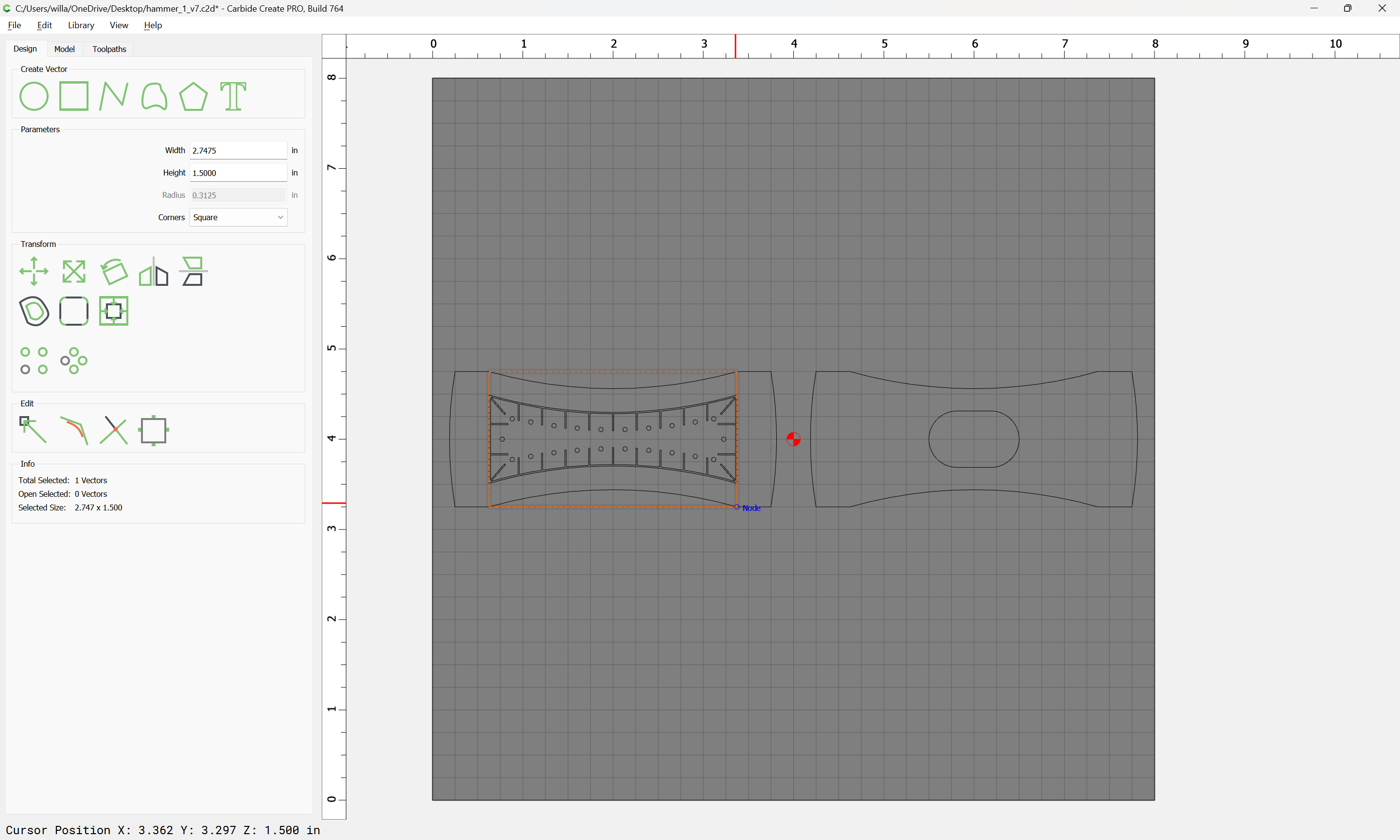
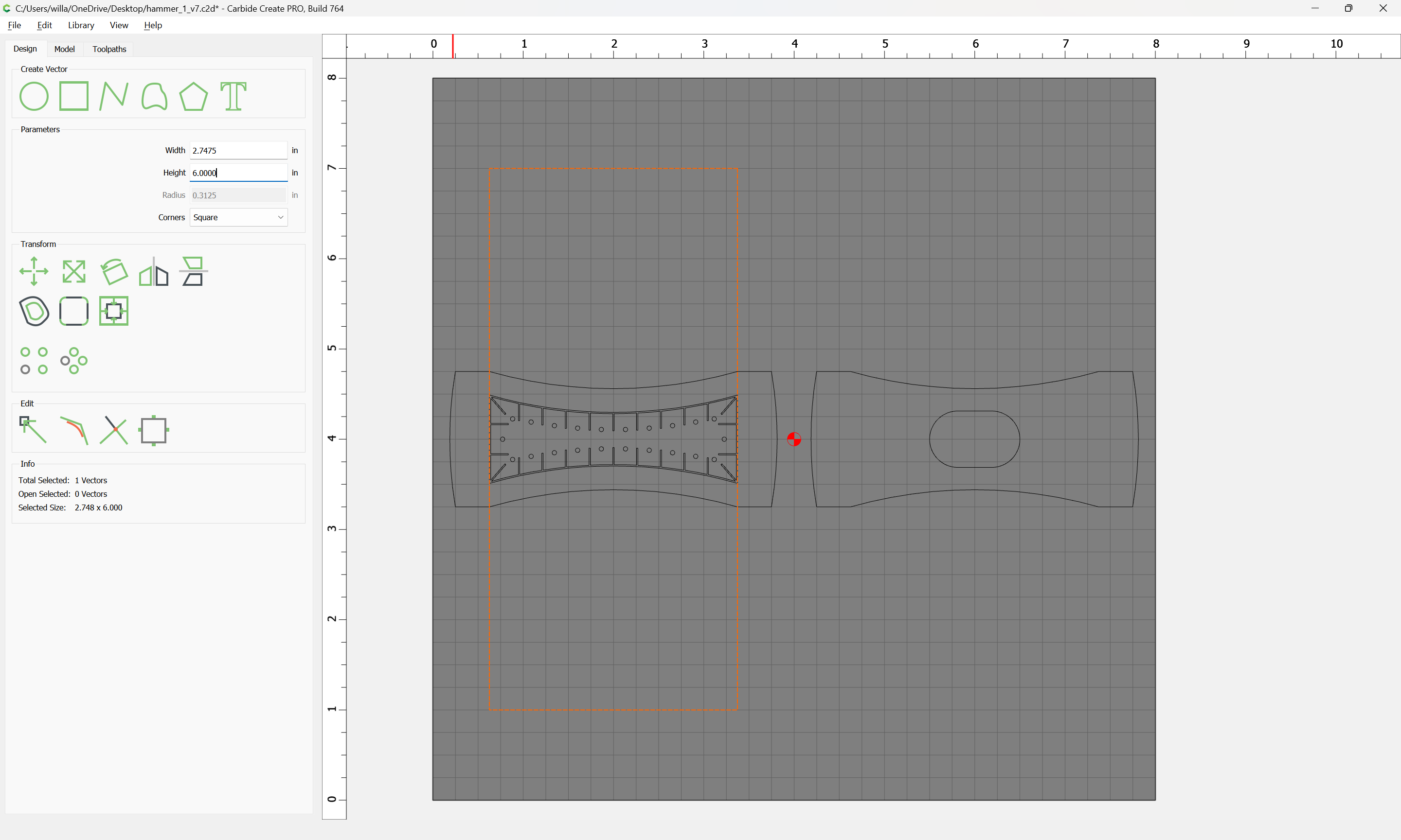
Set the stock size up:
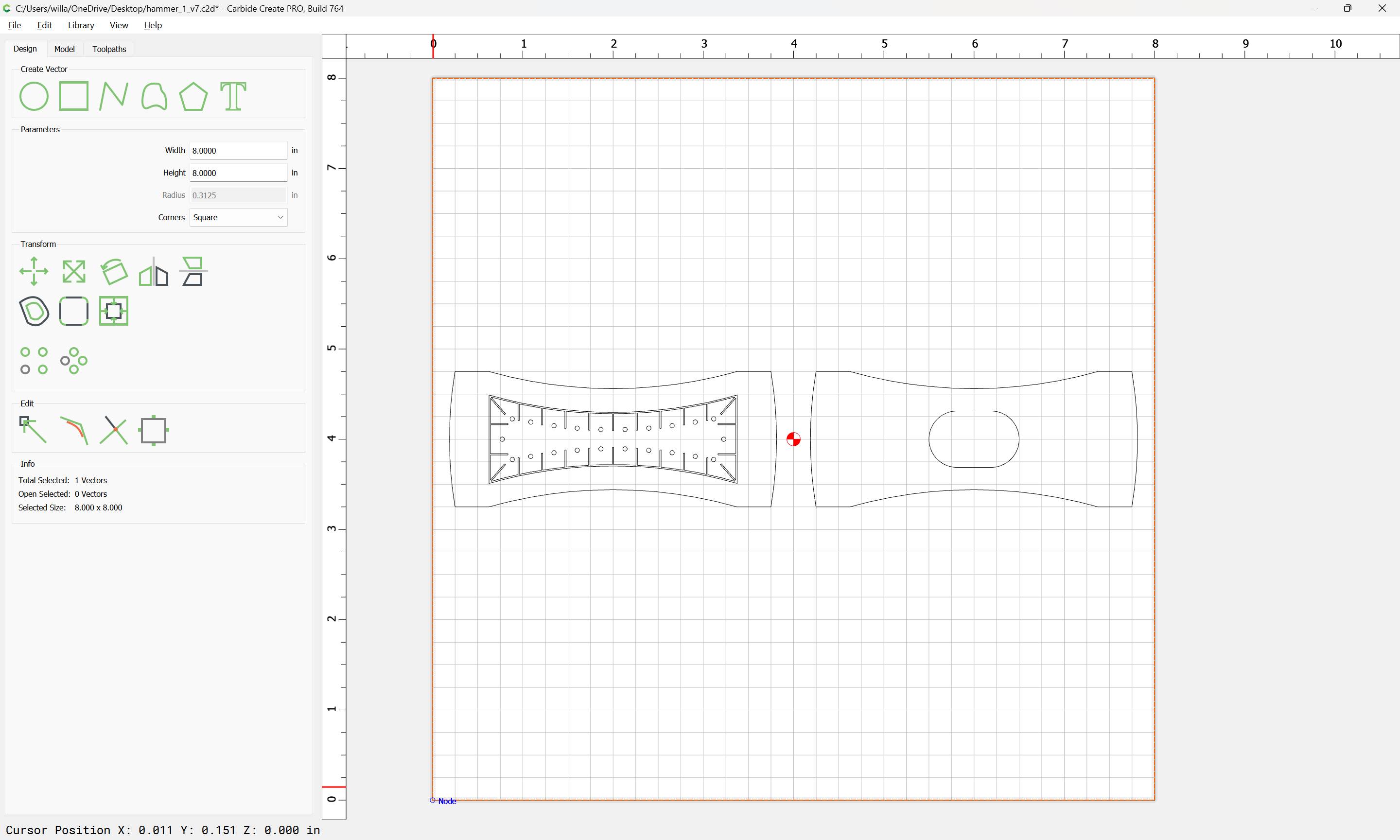
Re-save the file, then delete all but the necessary geometry, arrange things, and draw in geometry to model the stock:
WillAdams
February 2, 2024, 11:49pm
4
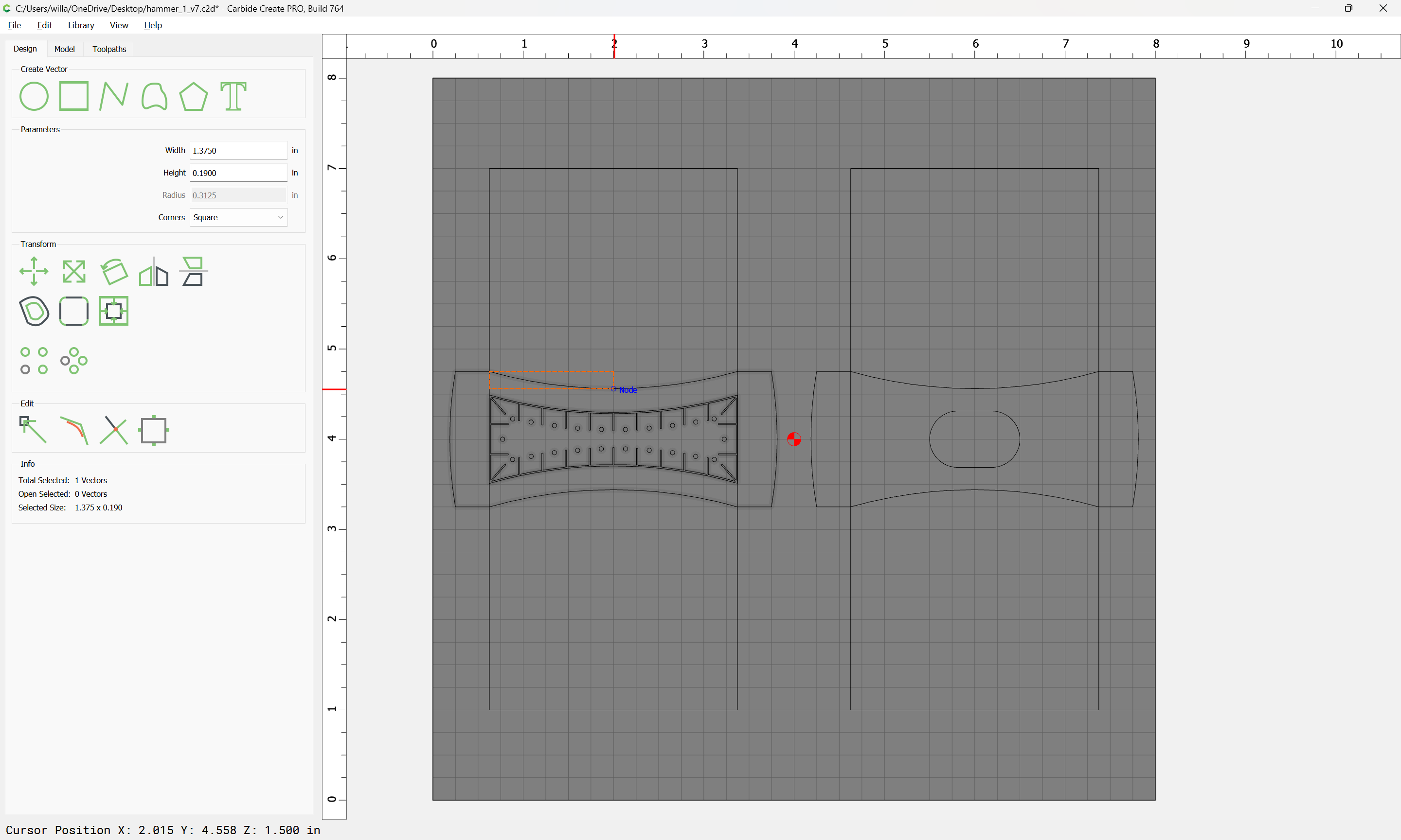
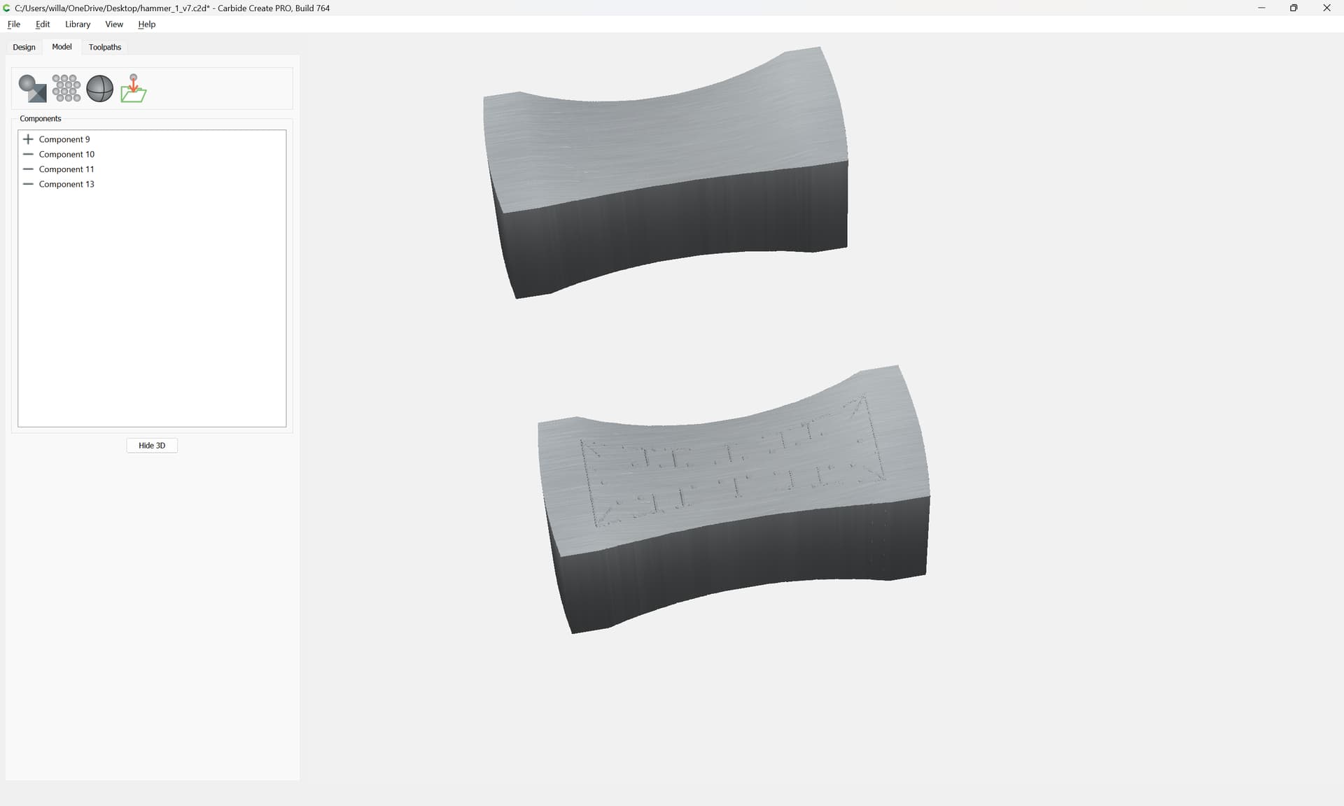
Then we draw geometry for rounding the center of the tops/sides:
and geometry to get the distance needed for the rounding:
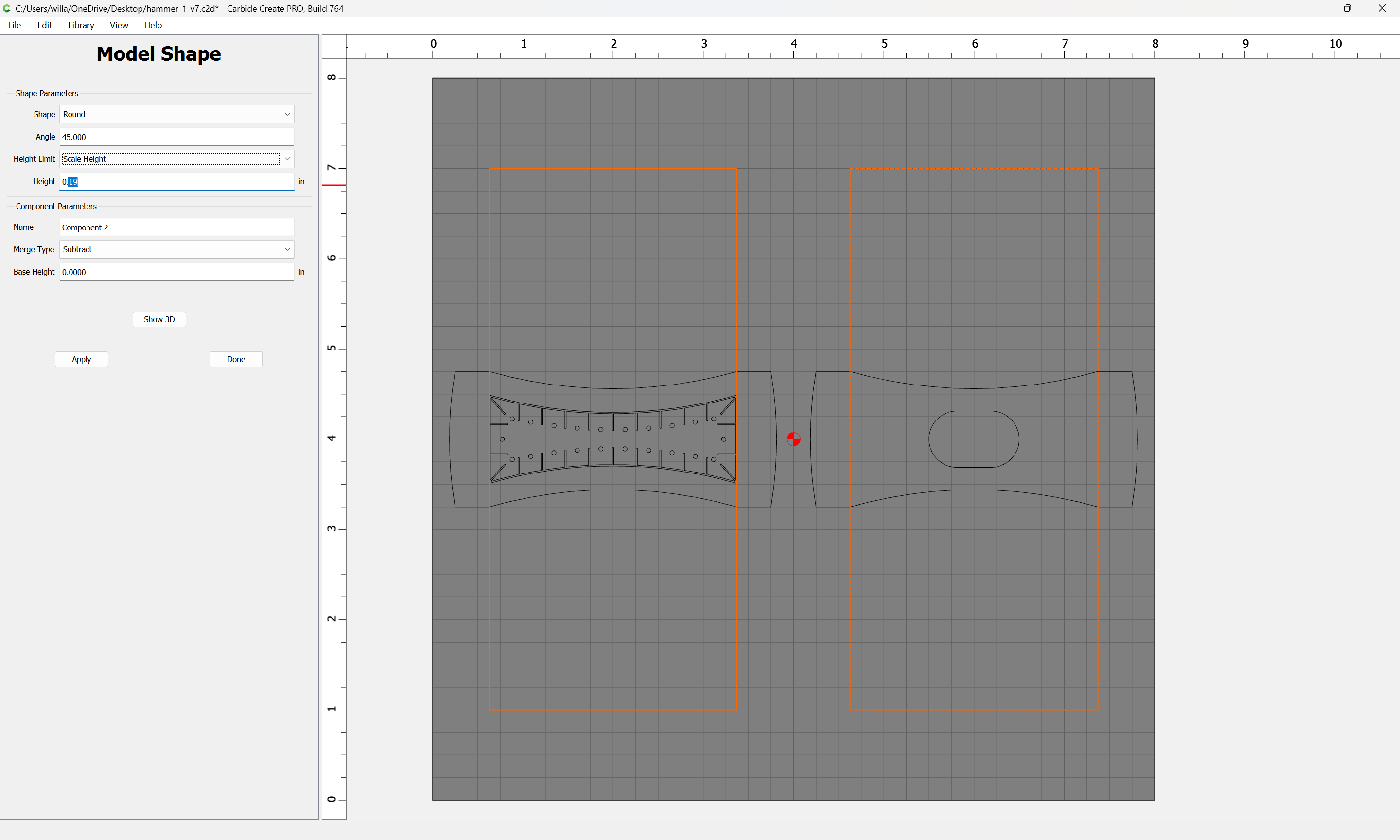
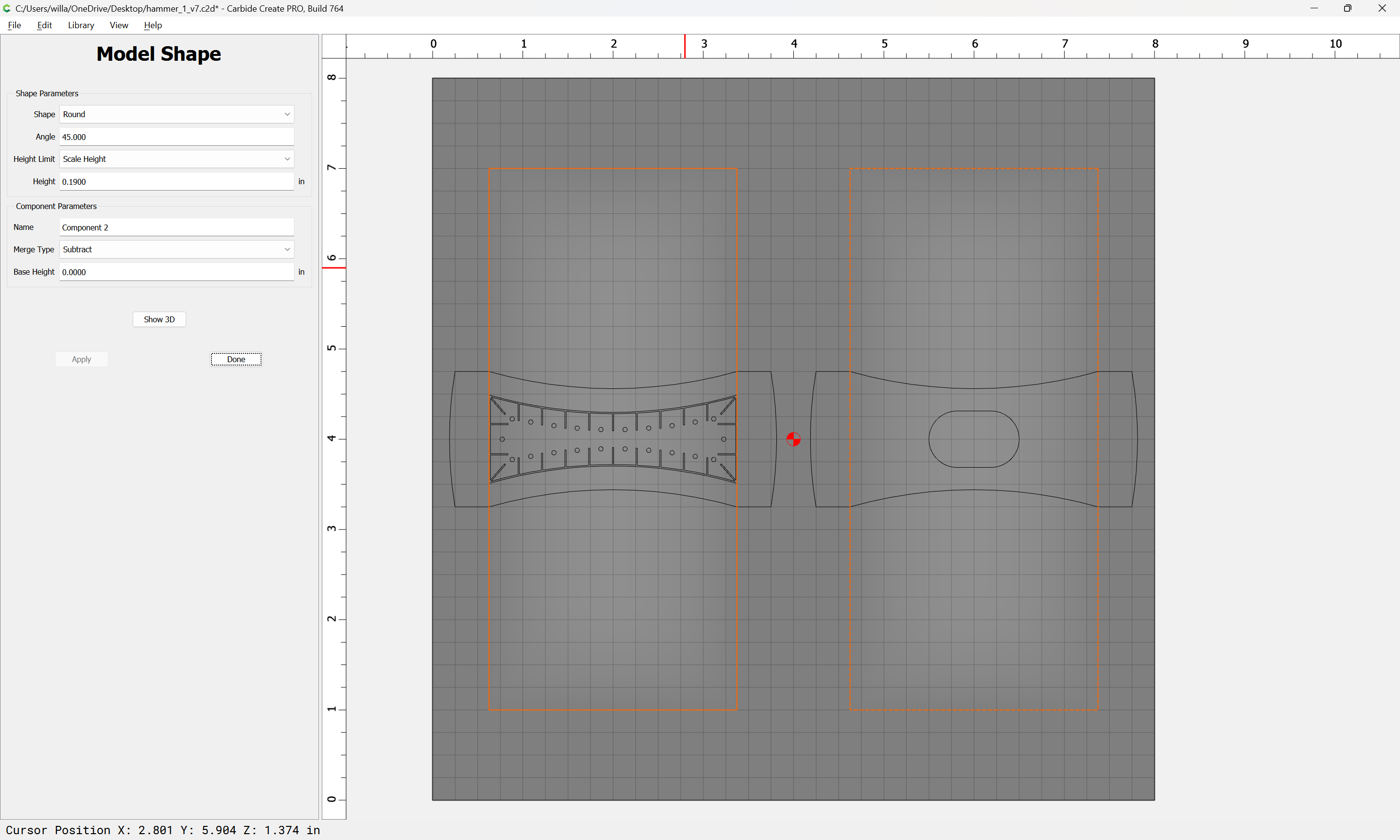
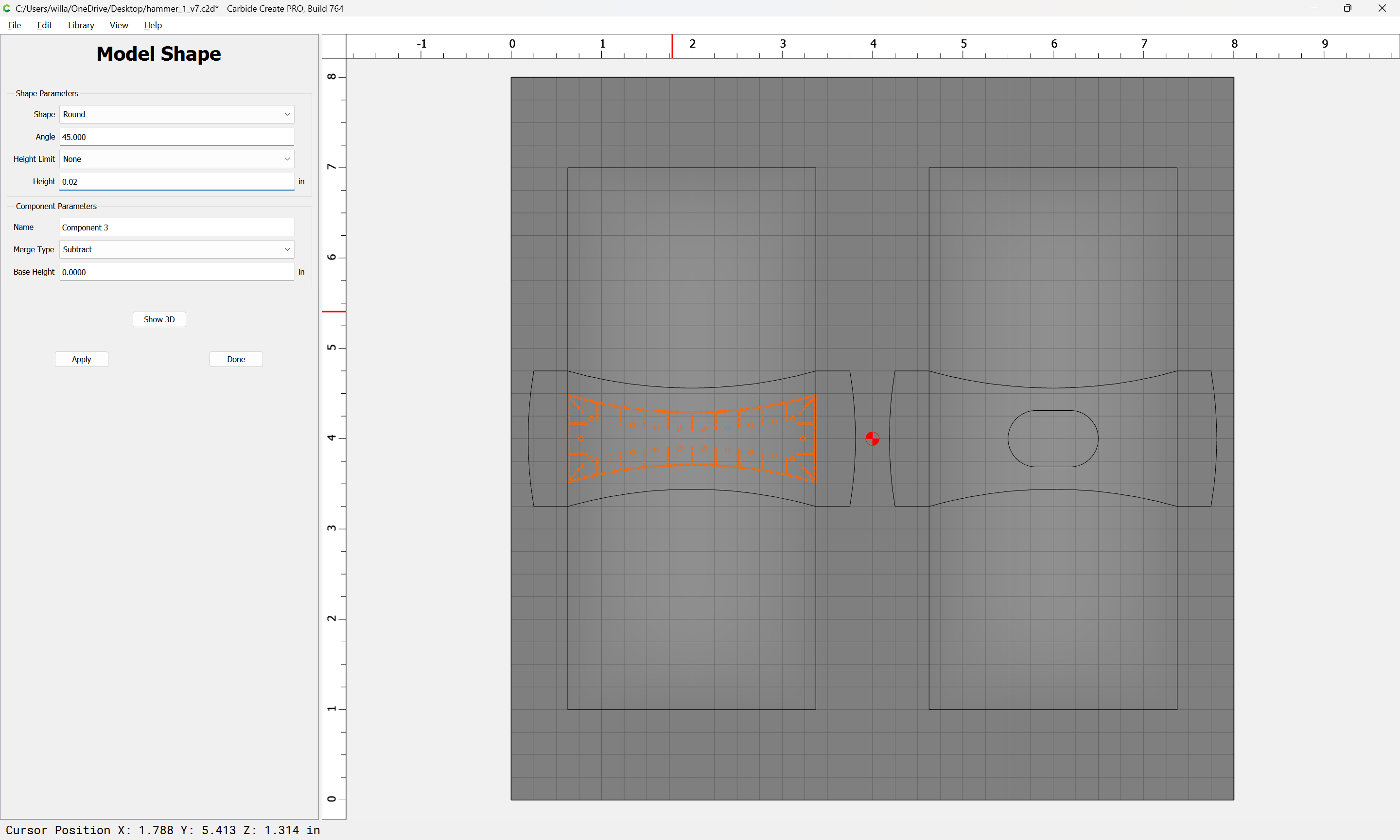
Select the geometry for the decorative element and subtract it:
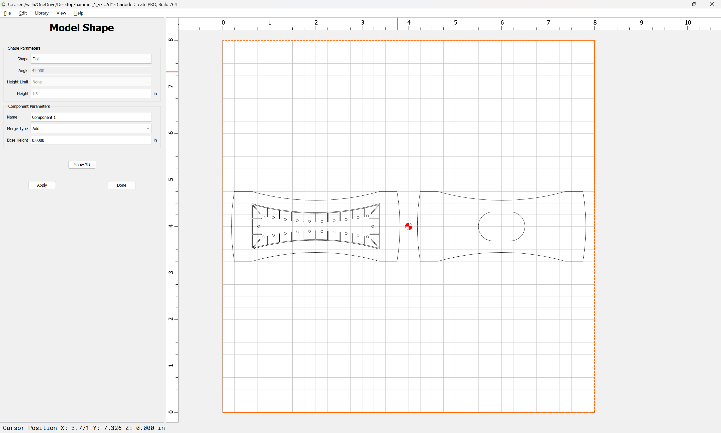
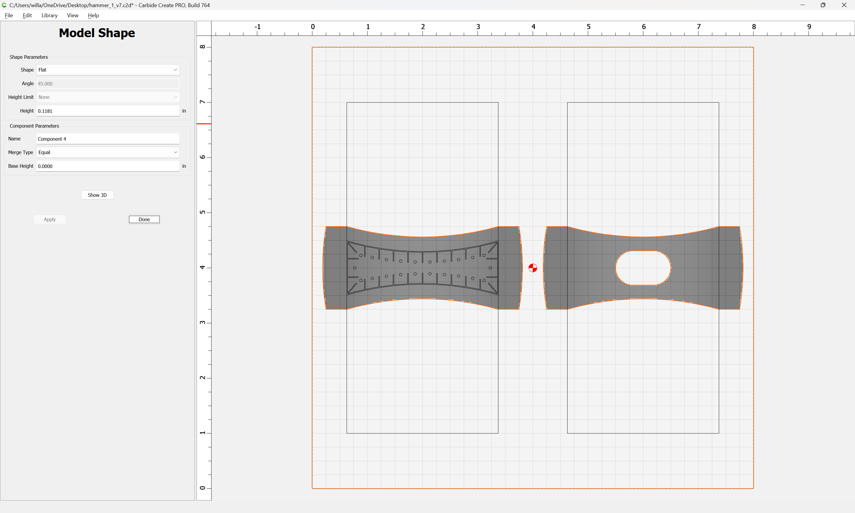
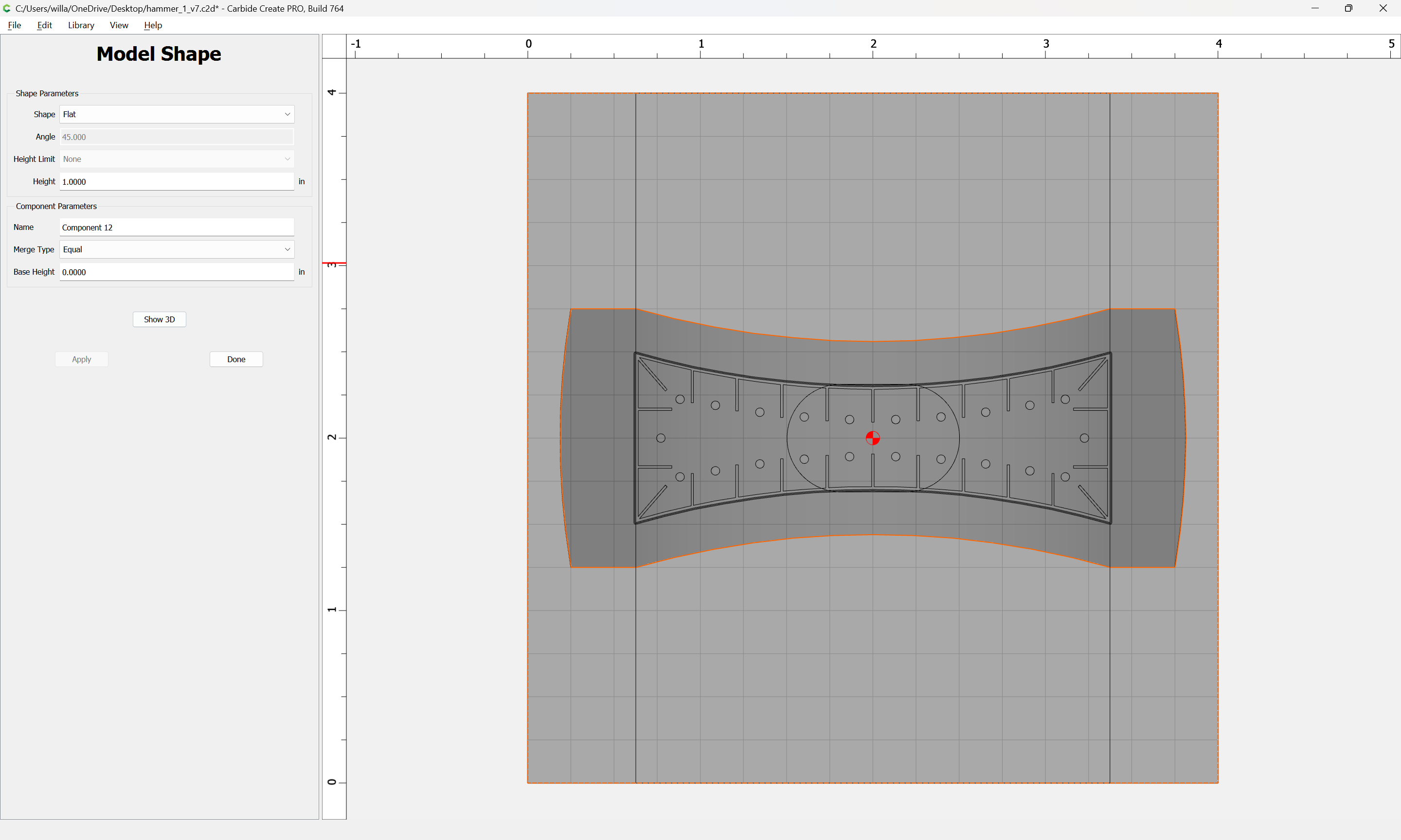
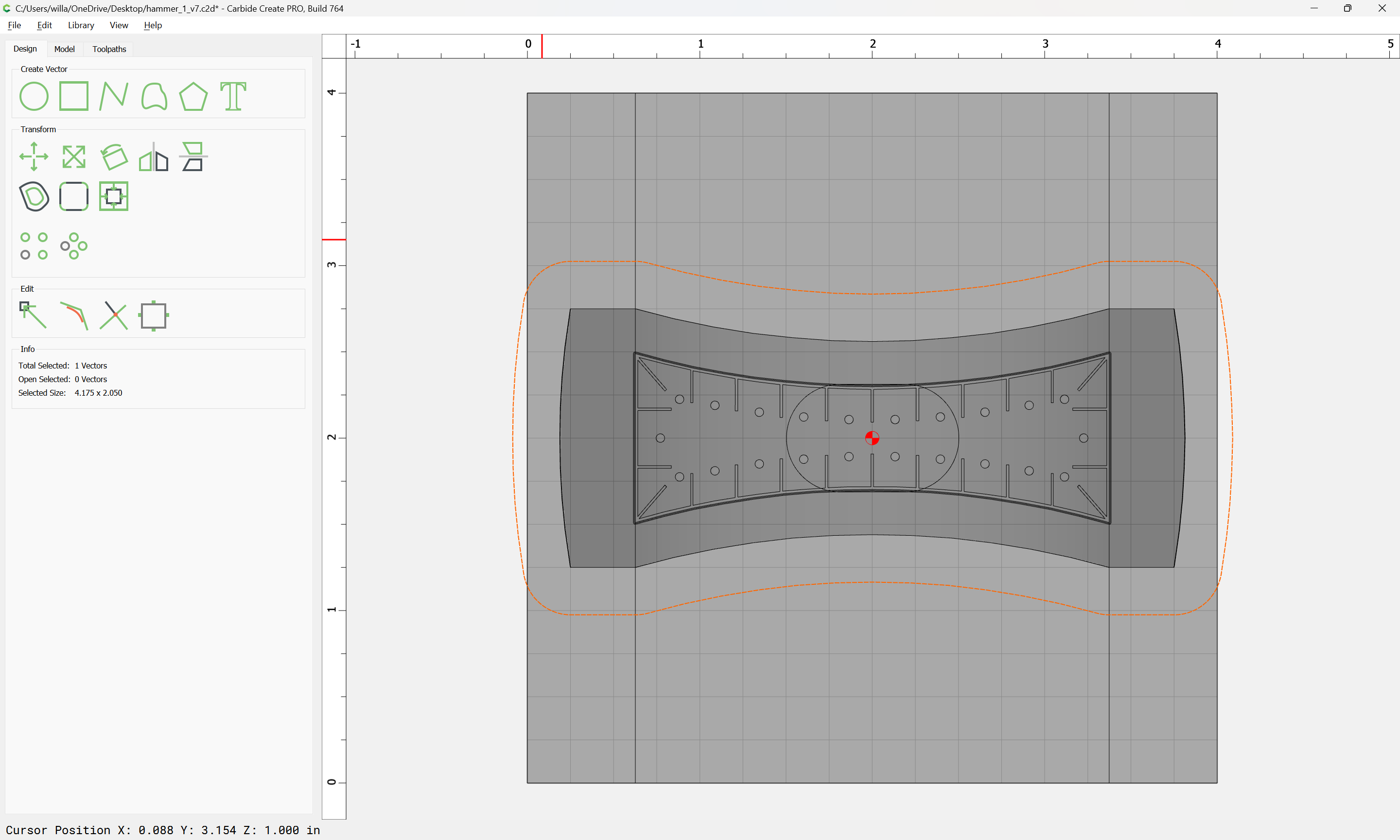
Select the outline geometry:
and set it to a height of zero so as to get a 3D preview:
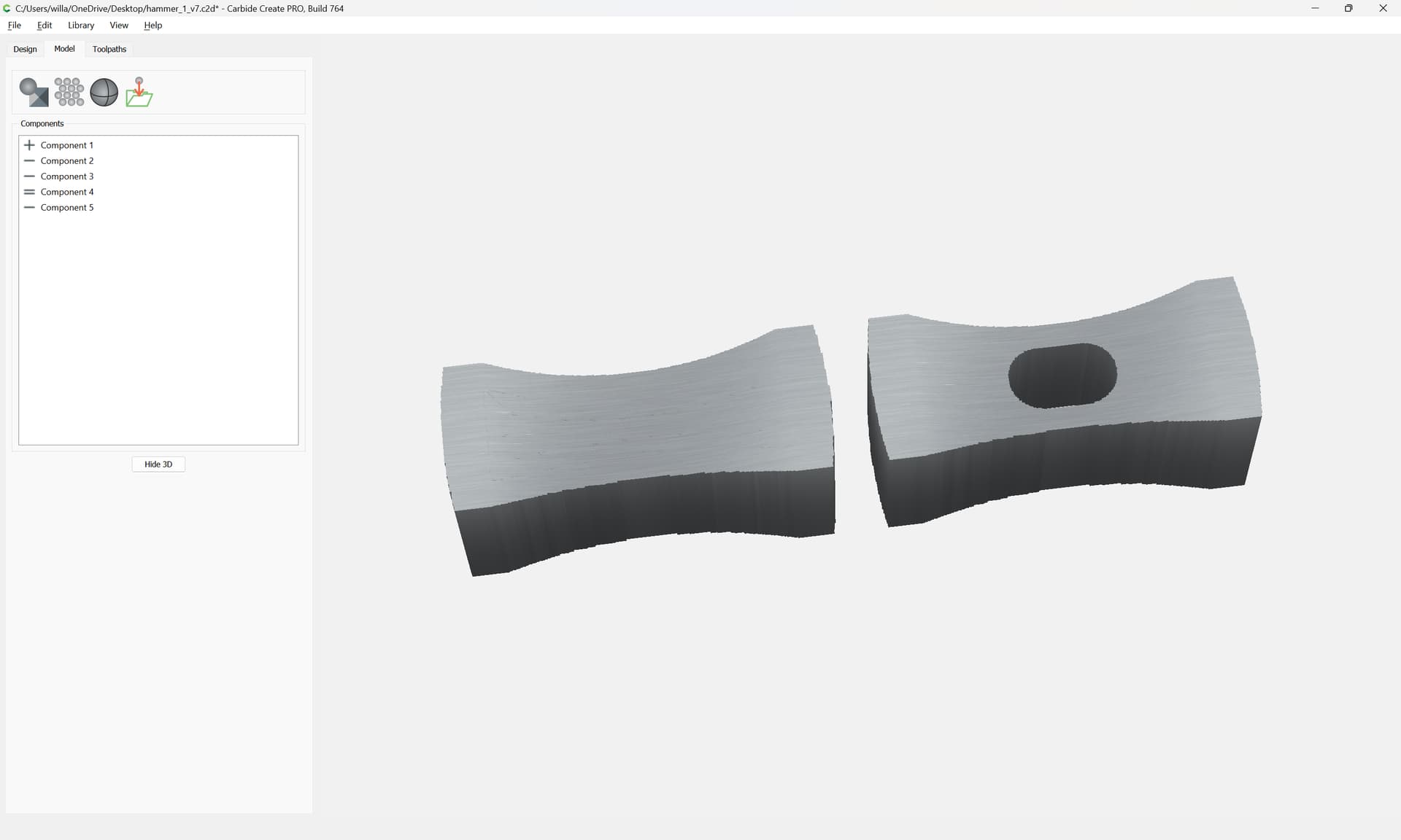
Rearrange things a bit:
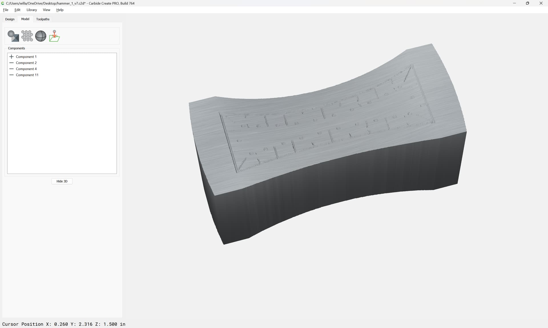
Eventually arriving at:
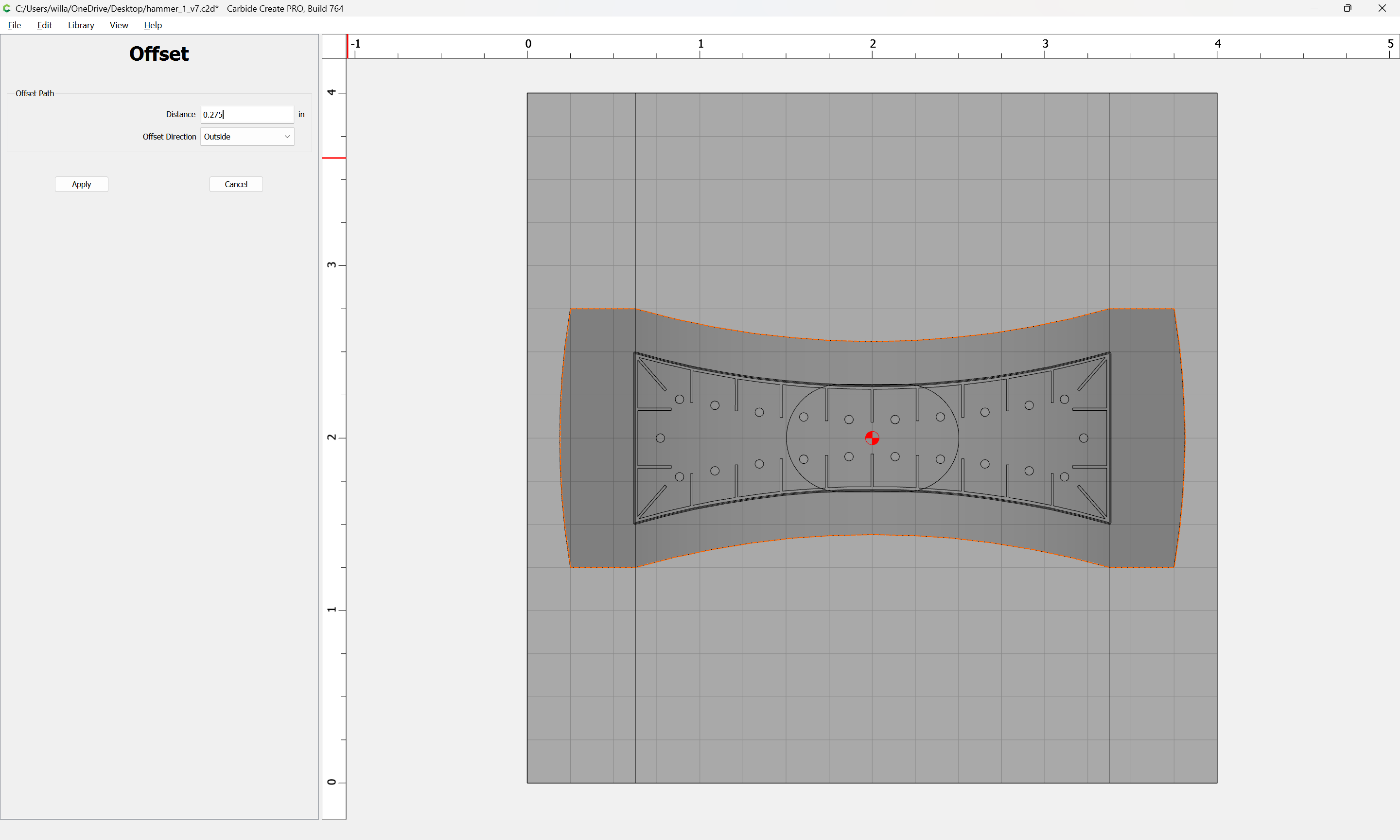
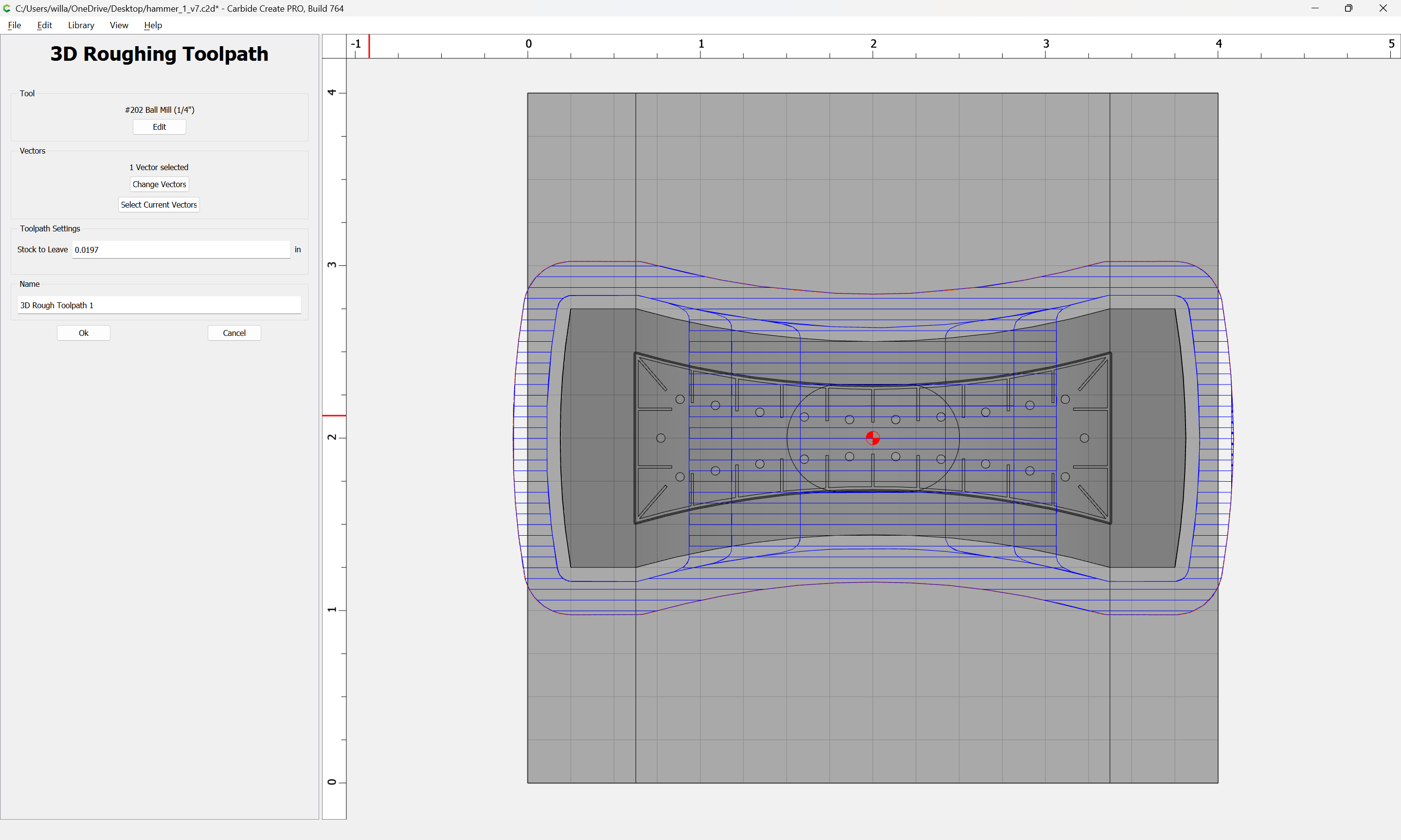
Then add stock to allow the 3D toolpaths to not cut too far:
Offset the outer geometry by endill diameter plus 10%:
Apply
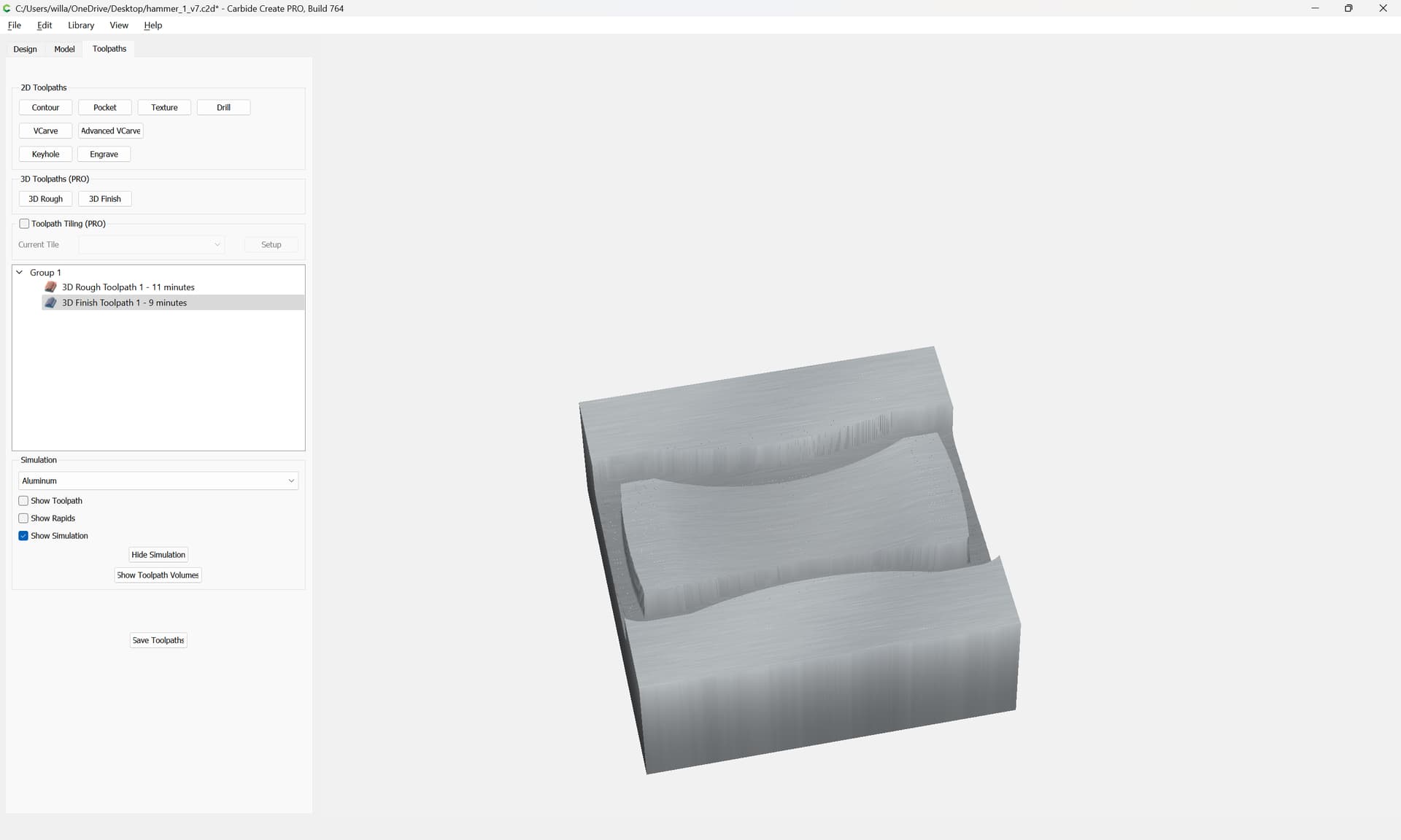
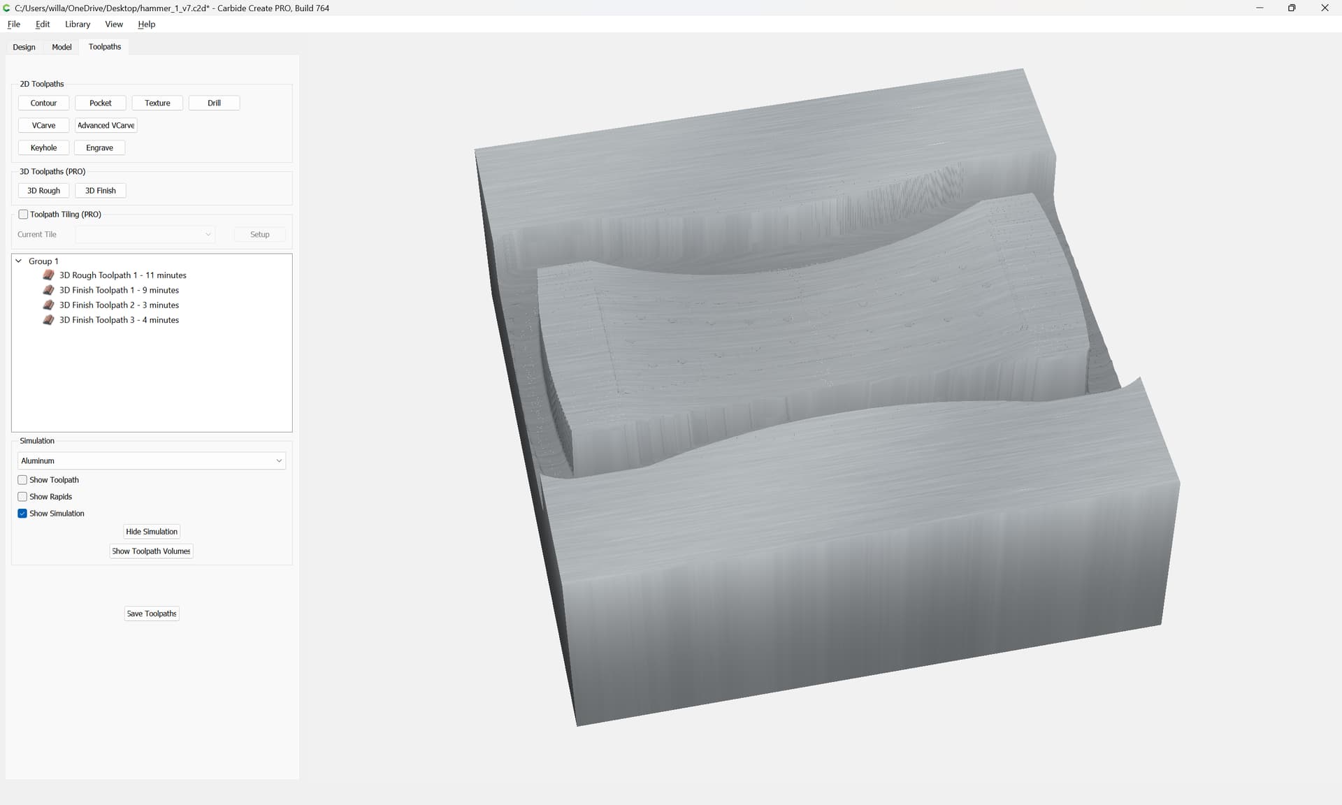
and then cut with 3D toolpaths:
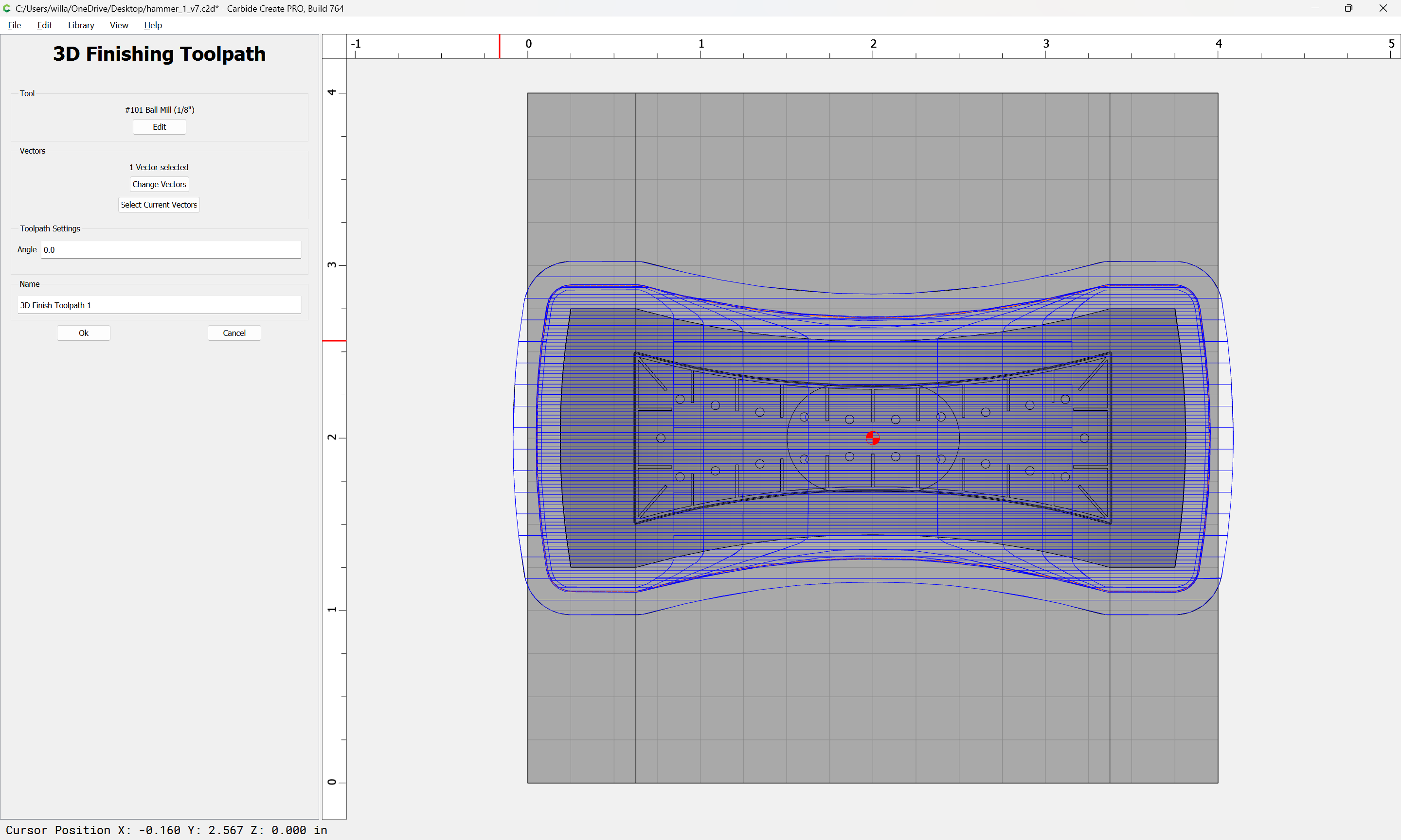
Add additional 3D Finishing toolpaths to arrive at:
For cutting the sides.
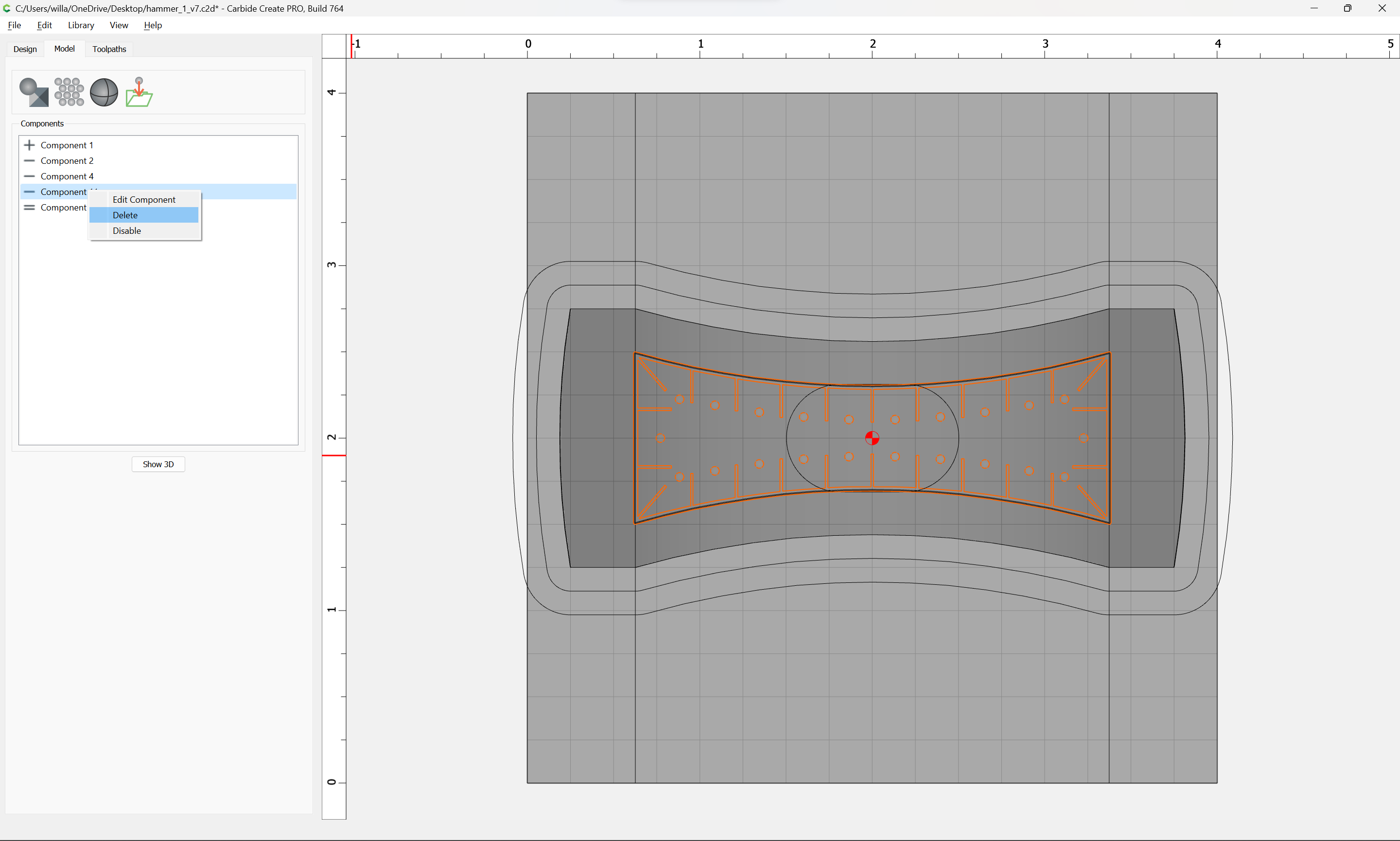
Then, to cut top and bottom, disable the detailing:
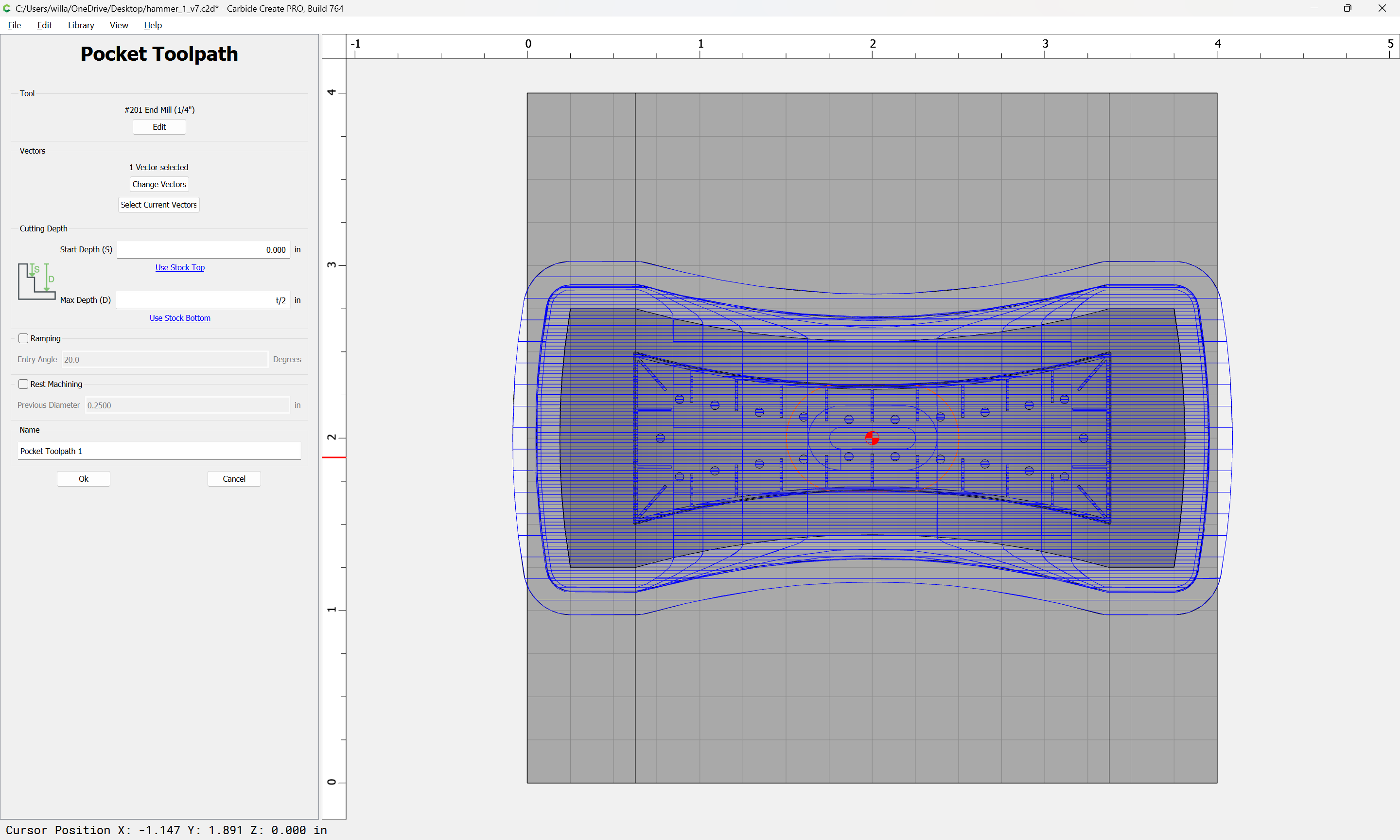
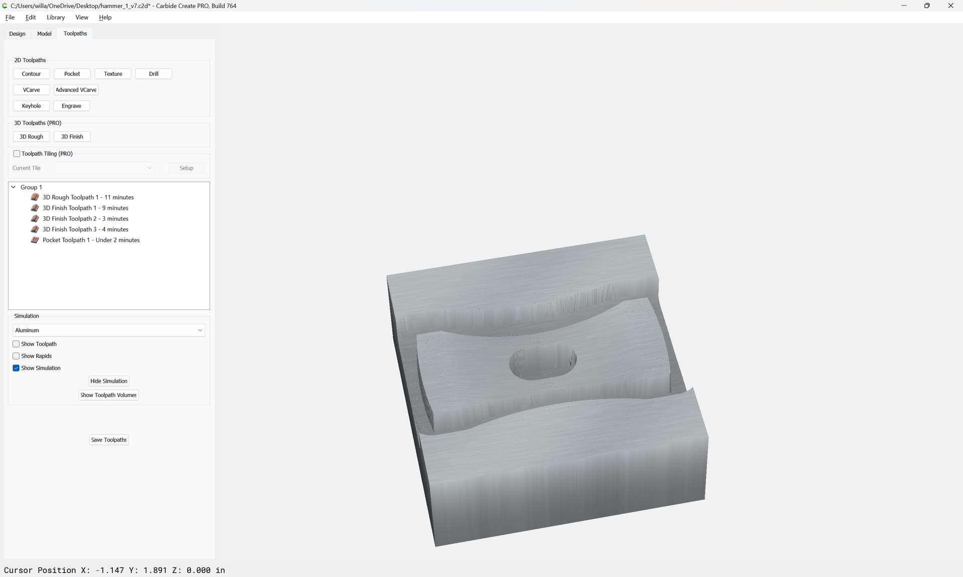
Create a Pocketing toolpath to cut halfway through the stock for the handle:
Output appropriate files, cut a side, rotate 180, repeat that cut, then rotate 90 degree and cut top, then rotate one more time to cut the bottom.
Then work up a fixture to secure the part and face off the ends — working up that design is left as an exercise for the reader.
system
March 3, 2024, 11:49pm
5
This topic was automatically closed 30 days after the last reply. New replies are no longer allowed.
WillAdams
June 16, 2025, 1:11pm
7
Not quite the same, and shown using manual techniques, but this video from Adam Savage goes over the balance of what might be involved:
WillAdams
July 1, 2025, 12:00pm
8
This topic was automatically closed after 14 days. New replies are no longer allowed.