Eric - I know it’s been a couple of days, but I just ran across your post and it really peaked my interest.
Specifically interesting to me was the fact that the visual shape of that fidget is complex and I think the complexity actually creates an illusion that makes it difficult to see HOW it was actually designed.
This isn’t a full tutorial, but should give you enough information to get started designing your own spinner.
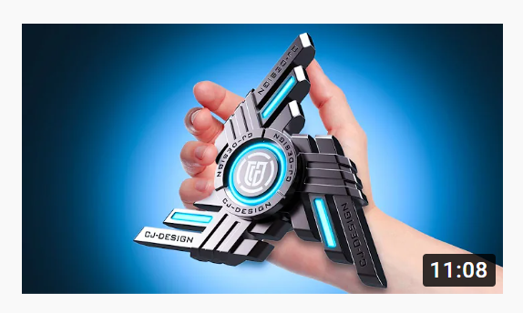
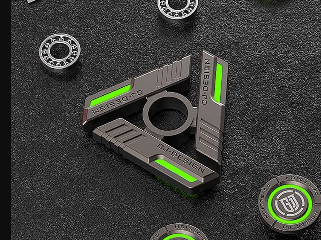
I went looking around the internet and found another spinner by the same company - this one makes it MUCH easier to see how to design - because this spinner, is actually just a simplified version of the one you posted originally.
Also - in the product listing they specified the bearing size (R188) - which is 1/2" OD. having a known dimension makes designing the other features to scale much simpler.
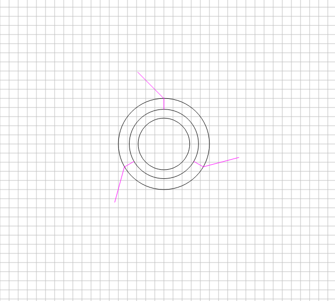
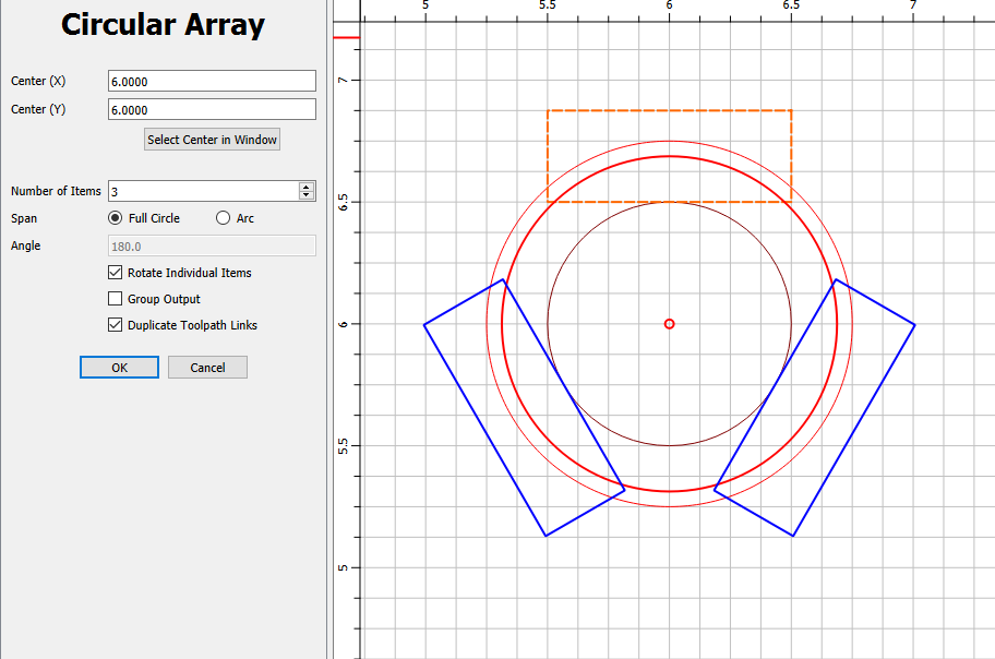
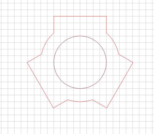
I started with a circle that was 1/2" diameter. Then outset the circle by 1/4".
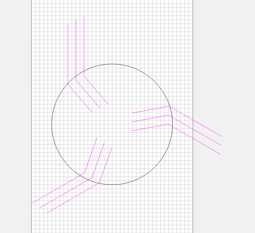
From there, you need to create 3 places which the arms attach to the center. I drew a rectangle that was 1" wide by .5" tall - then used the circular array feature to rotate that shape around the circle.
If you select the outside circle and the 3 rectangles you can use the Union boolean command to create the shape of the hub.
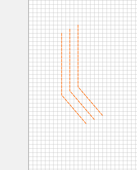
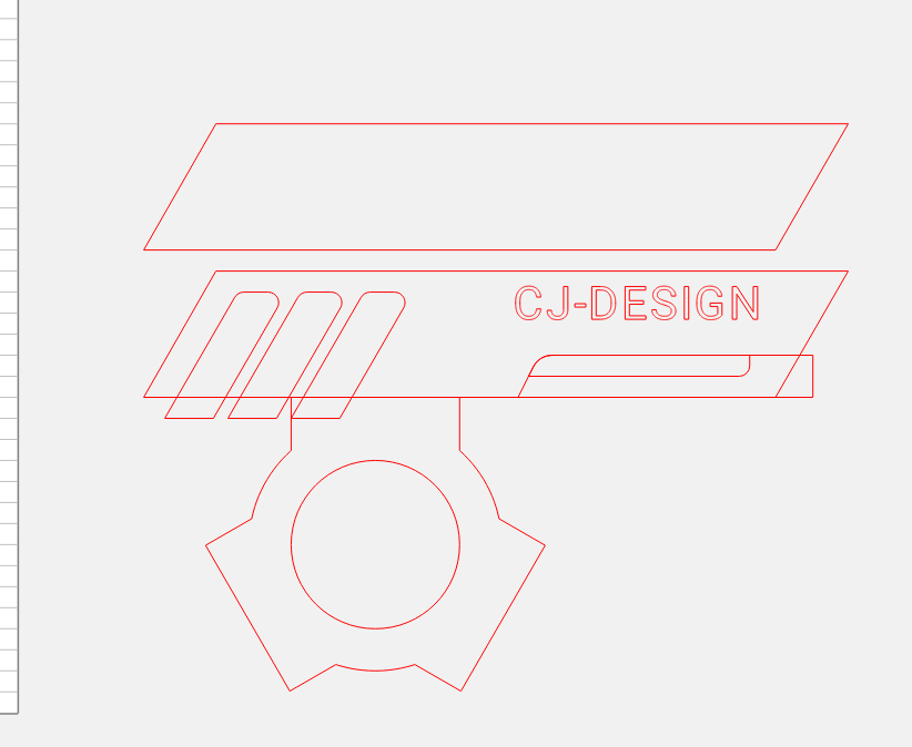
From here you can just copy the design from the image or create your own thing - then once you are happy with the design, create all of the toolpaths for one arm.
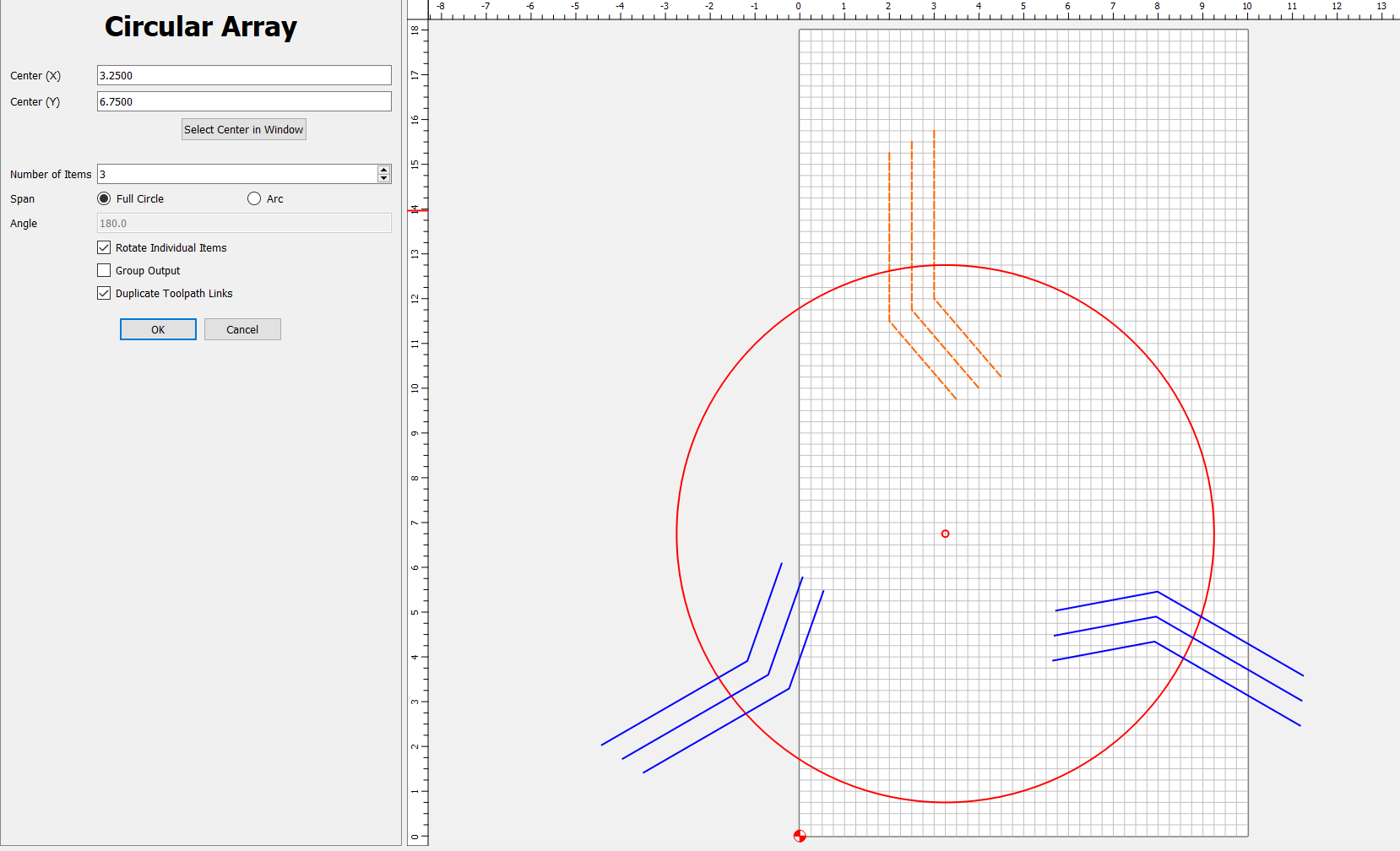
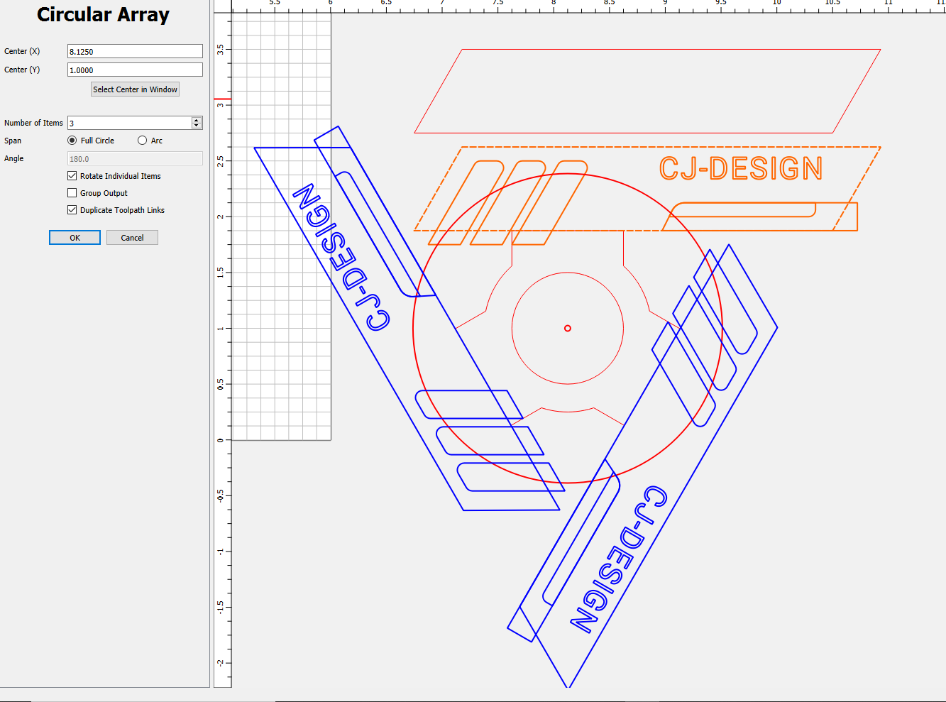
I came back to design mode and used the circular array tool (using the center of the circle as the rotation point) (be sure to duplicate toolpath links option!)
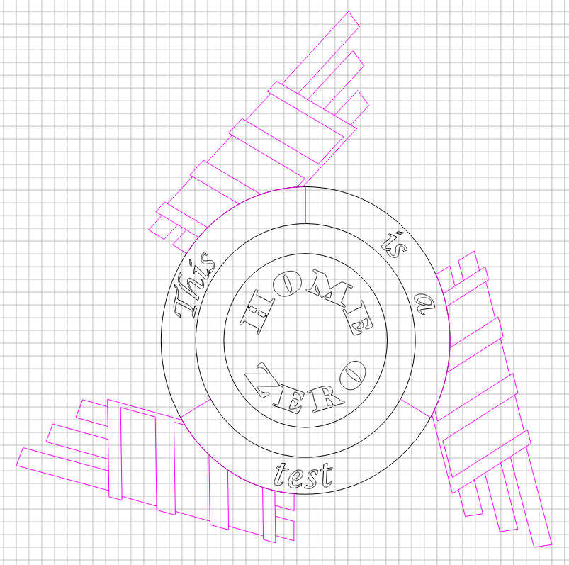
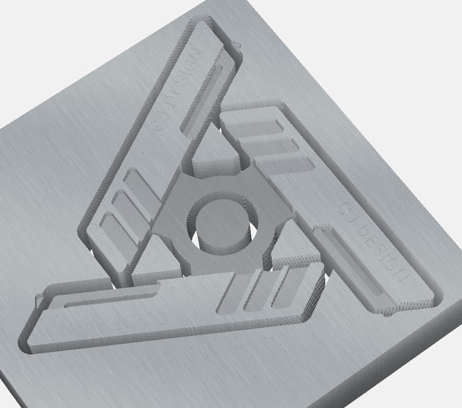
After that was complete I did another Union Boolean to attach the 3 arms to the center hub. And then created a profile operation to cut the part through the material.
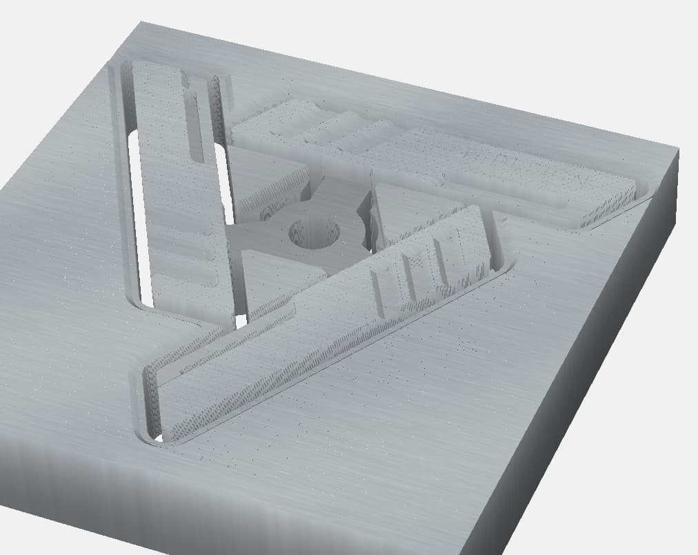
I’ve attached my design file (CC v7) with a few additional components for you to reference. Also, I created toolpaths so I could run the simulation, but they are not vetted, tested, and certainly not optimized!
Edit: I added a second file with some more toolpathing - nothing ground breaking - just added a chamfer to the edges. Also left a few more copies of the design in progress so you could see how I was creating the final shapes.
-Edward
fidget_shape.c2d (240 KB)
fancy_fidget_shape.c2d (468 KB)