Making a street sign for our neighborhood using high-density urethane material.
Machine is Shapeoko Pro
Carbide Create Pro Build 743
Carbide Motion Build 578
Font Used: Century Schoolbook
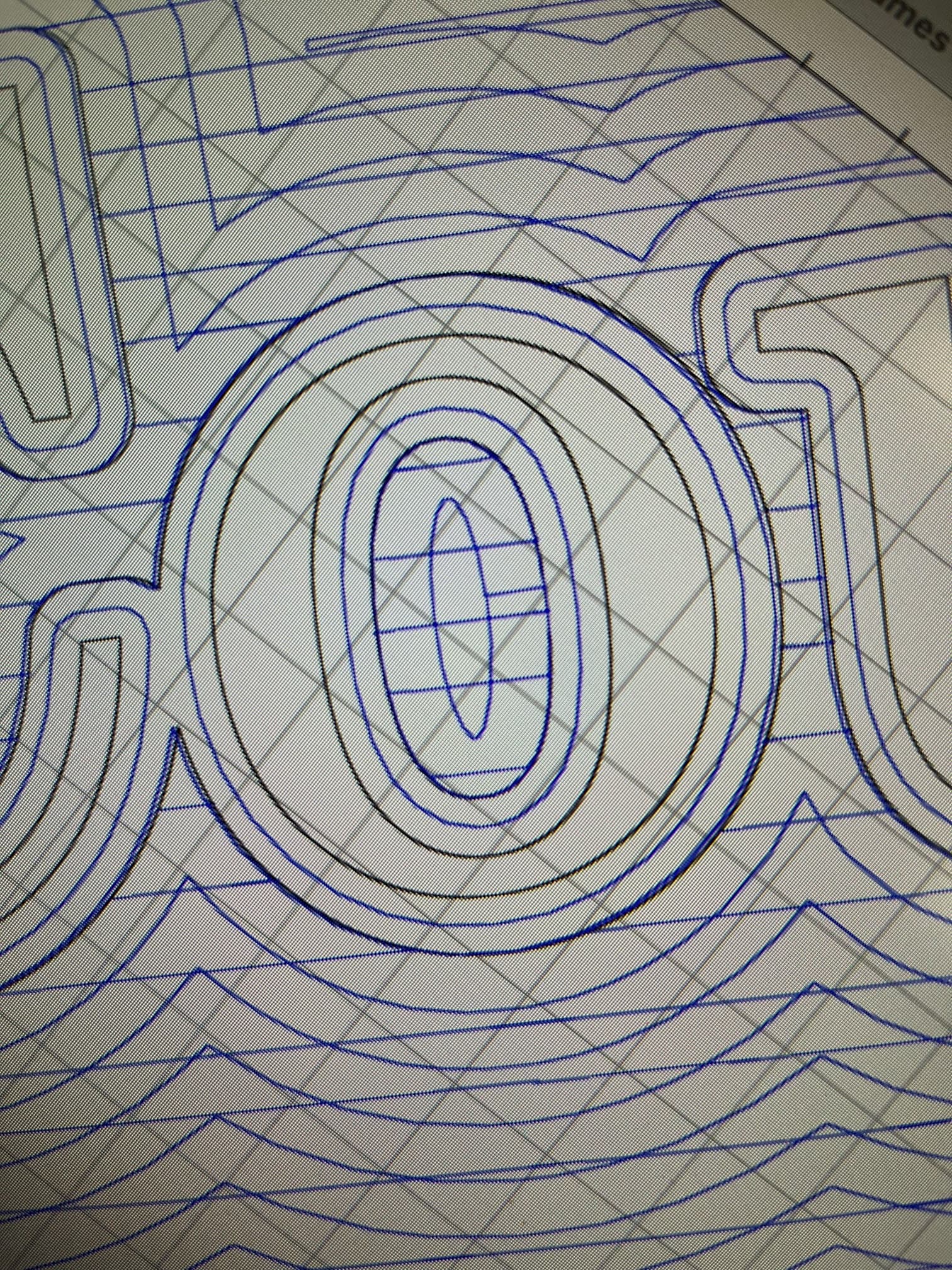
This image shows the program for the letter “O” in Carbide Create:
When it happened the first time, I thought the machine had slipped a notch on the X or Y belt(s) or some such problem. Checked the machine and all seemed tight and well. Sent the router to original XY Zero point and everything lined up correctly. Ran the project a second time to create the carving for the reverse side of the sign and encountered the exact some problem. The second running of the program was a mirror image of the first side but contained the same problem with the same location of the same letter.
I don’t think it is a machine issue but would guess the problem must be in the G-Code somewhere. My problem is that I am now trying to operate well above my pay grade!
Please post the .c2d file, step-by-step notes on how you are securing your stock and setting zero relative to it and how you are managing all tool changes.
Posting screen grabs showing what you are seeing on screen and expecting vs. what actually cut will help as well.
The inside of the “o” was the last item cut on the sign. The r and t of court were the very first two letters cut in the entire sign. It would seem to me that it something was loose, the machine would not return to the original X Y zero point after the project was run. Also, would it not seem strange that I would run the project a total of three times with the exact same result if the issue was something loose or the material moving. I would feel the same regarding “some missed steps (X movement not accounted for).” Taking all of that into account, I keep coming back to something missing the the coding itself. I will be sending the .c2d file requested to WillAdams when I return home this afternoon,
if you don’t trust it… there is always the “camotics” open source tool that will simulate gcode (you do need to program in the tools you are using)… that is what is sent to the machine basically…
… and is a good way to do the “was it on the digital/design side” or “was it mechanical”
or for not-compex 2D-ish designs… “ncviewer” is also great, and can just run in a browser
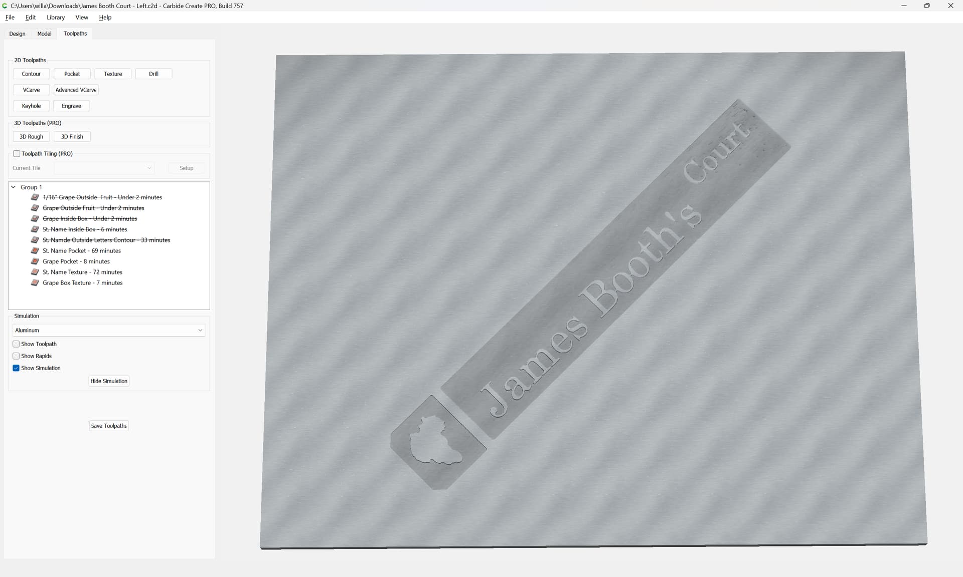
The file above is the 2d file for the sign in question.
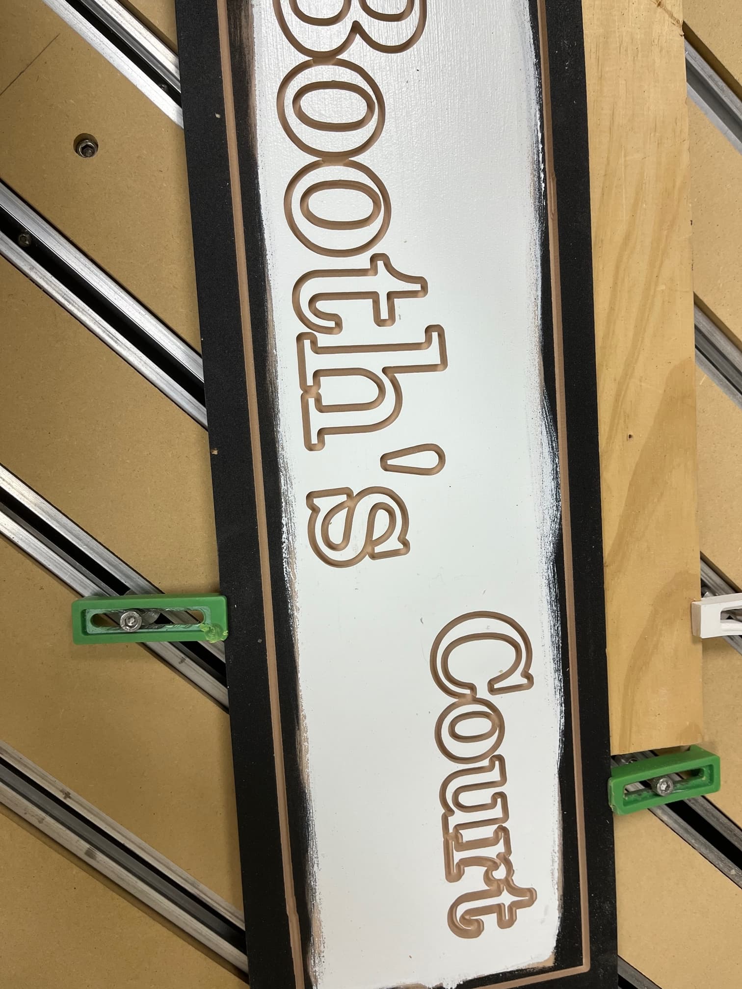
The work is secured with four of the green hold clamps that came with the machine. The material is High-Density Urethane which cuts like butter and offers very little resistance to the movement of the bit through the material. Zero was set to the center of the work and was checked after the running of the project and the zero alignment was right on the mark which I believe rules out the movement of the work or jumping a cog in one of the belts. Tool changes were made when required when moving from one tool-path to another as the machine worked through the carving of the sign. The machine would stop and request the necessary bit change as necessary. I believe the pictures in the original post shows what was called for in Carbide Create an what the result was. My major concern was the problem with the “o” in Court but as noted in other’s responses, there is also an issue with the “r” and “t” in the same word which may be related to the same problem.
The sign shown here and a mirror image made from a copy of the same file resulted in three signs with the exact same issues as covered here.
Again, thanks to all who have replied to my issue.
(for HDZs, and HDMs, and SO5 Pros) check that couplers between the motor and ball screw are secure, for the SO5 check that the DAC which transfers the rotary motion of the ball screw to linear machine motion is secure on the carriage/gantry
Belt tension (see the relevant step in your instruction manual, e.g., Getting Started with Carbide Machines) Note that the X-axis motor is held in place on standoffs and if those bolts are loose this can cause belt tension issues. Also, belt tension for the Y-axis stepper motors needs to be even/equivalent on each side — a significant difference can cause skipping on one side eventually resulting in lost steps on both. Measuring belt tension, squaring and calibration
A good video overview on setup:
Ensure that all screws are in place and secure, esp. on the linear rails on a Pro.
Also verify that all wiring is in good condition and all connectors are secure, and that all wiring leading into connectors are properly in place.
I am not sure I understand your concern. However, the top picture reflects all of the tool-paths necessary to complete the sign while the third picture shows the sign in progress after the outer contour of the letters has been carved but before the pocket operation around the letters has been performed or the final texture tool-path. It while carving the contour of the letters when the error happens and I believe that the pocket and the texture tool-paths repeat the error in carving for the letters o, r, and t.
Thank you for your interest, if this response does not cover your question, please come back for more.
Thank you for your effort and detailed input. Is it possible that there was some form of hick-up internal to Carbide Create which resulted in the error which produced the repetitive nature of this issue? If so, perhaps starting from scratch with a clean slate might product different results. I just have a problem thinking that an electro-machanical problem would repeat itself in the exact same point on three different carving of the same program. Especially when the location of the problem moves about 22" when carving the mirror or reverse side of the sign while using the exact same zero for X, Y and Z.
I have checked the machine, to the best of my ability, for any loose hardware or belts. The moving parts of the machine move without binding when there is no power the the machine. I have cleaned and lubricated the rails. With power to the machine I have tried to move the various moving parts of the machine and notice no sign of movement indicating a loose pulley similar problem.
I think the next thing for me to do is to repair this sign to the best of my ability by carving just the letter “o” and gluing it in place on this sign. I will then reprogram a sign from scratch with the word Court repeated many times to see what results.
Thanks to all for your help which has been very much appreciated. I am still operating above my pay grade, but with all of your help I feel a lot better about it!
Sometimes mechanical issues can be quite repetitive — the machines are designed for repetition after all — but we can’t advise on things we don’t make, so all we can do is verify our software.
WillAdams
Another chapter in the ongoing saga…
This afternoon while trying to run the last tool-paths on the sign, while cutting the St. Name Pocket, I encountered a “ GRBL Not Found On Device”. message. Could this be related to my problem?
Also, has anyone documented a detailed step by procedure on how to restart start a tool-path a a known current line number position? What I was able to locate on line seemed to assume a high level of computer expertise. Thank you.