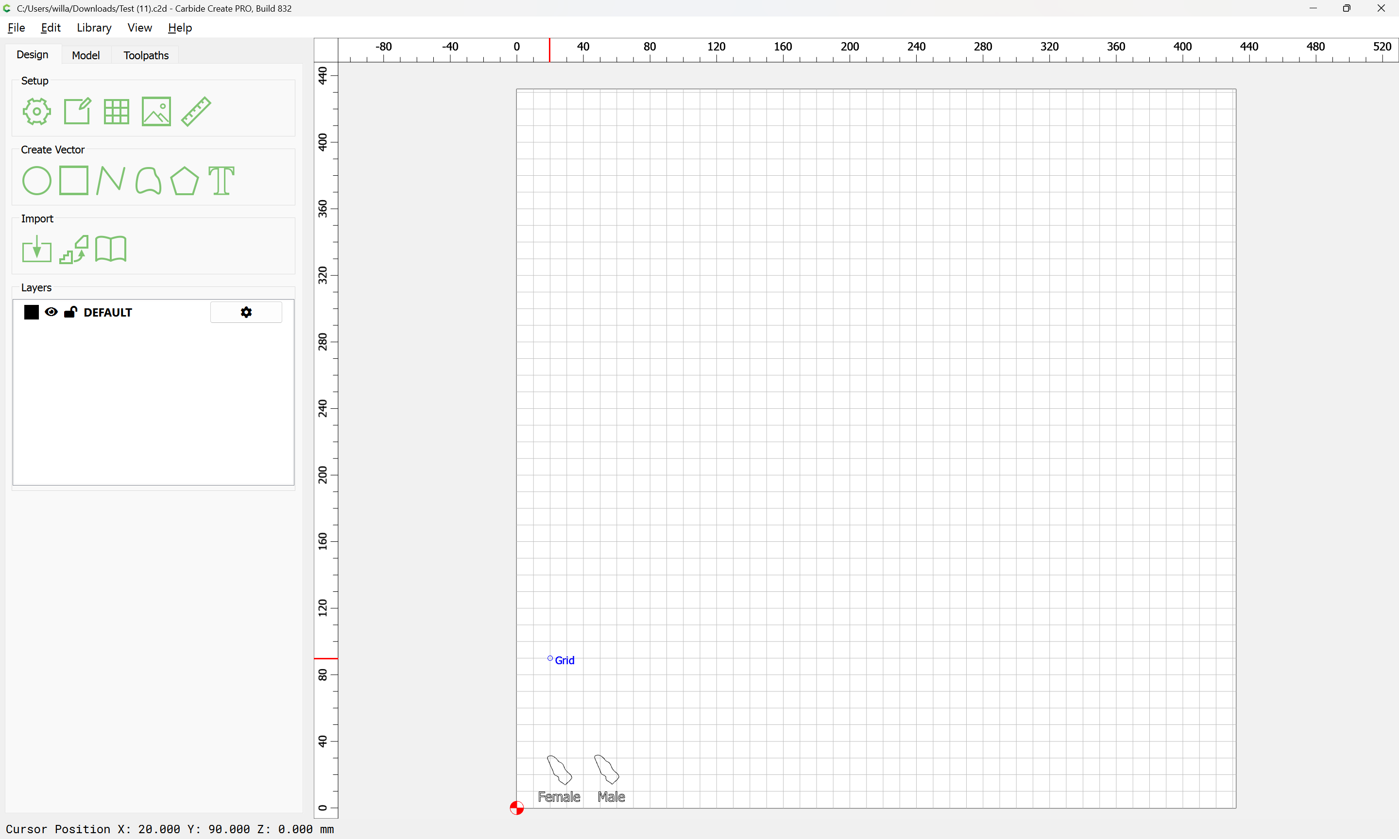
I am having problems with doing an Inlay. The Male /Female do not align correctly. Not really sure if this is the correct way to do an inlay.
Thanks John
Test.c2d (112 KB)
Did you forget to mirror the inlay?
Note that for this sort of through inlay, it will be necessary to take tool geometry into account (which is why V inlays are more typical)
For V inlays see:
For the sort you are trying to make, you will need to inset by the tool radius:
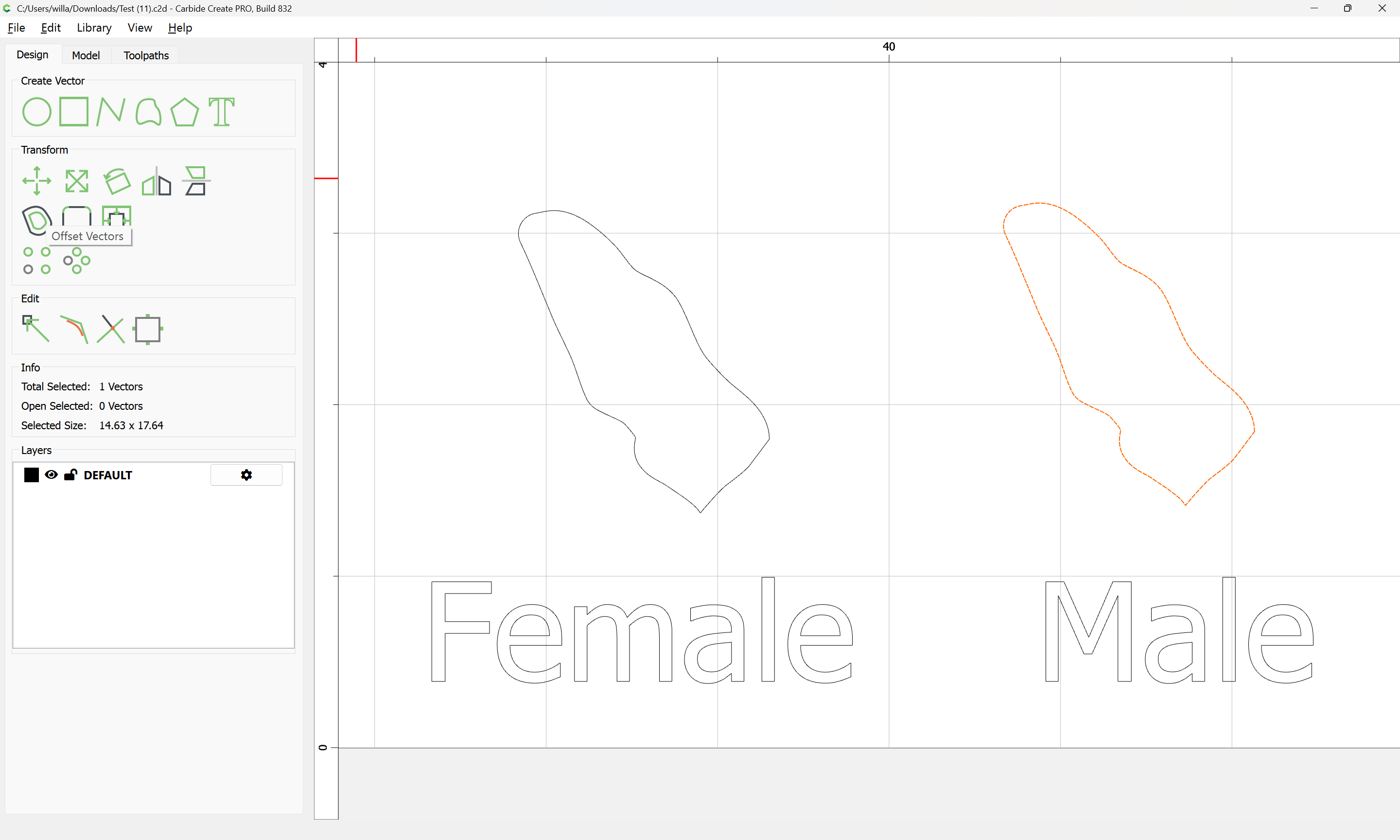
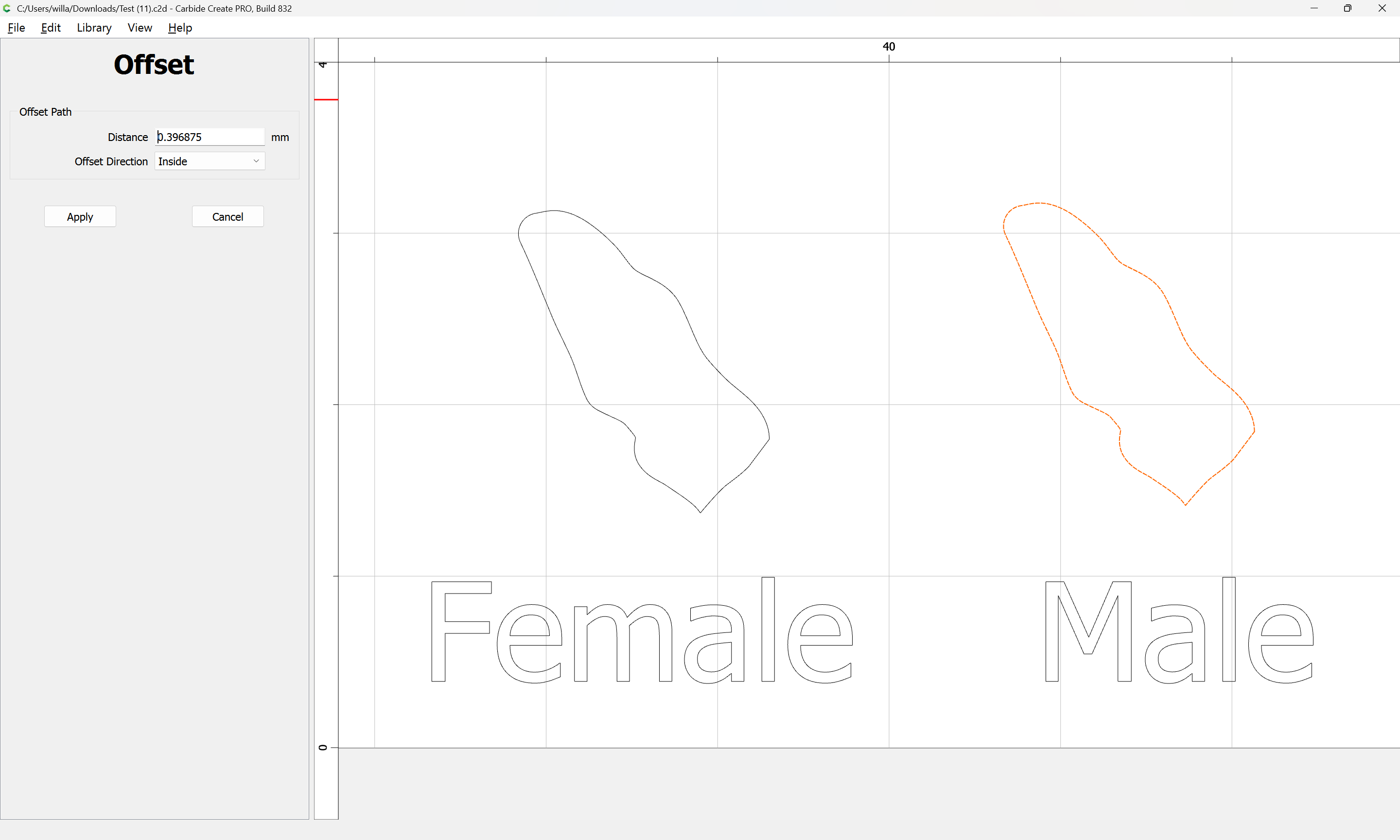
Apply
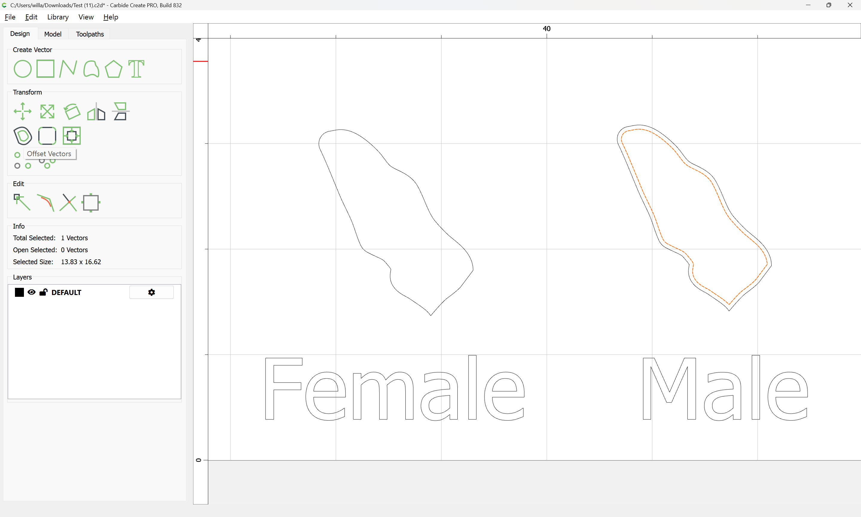
and then offset to the outside by that same distance:
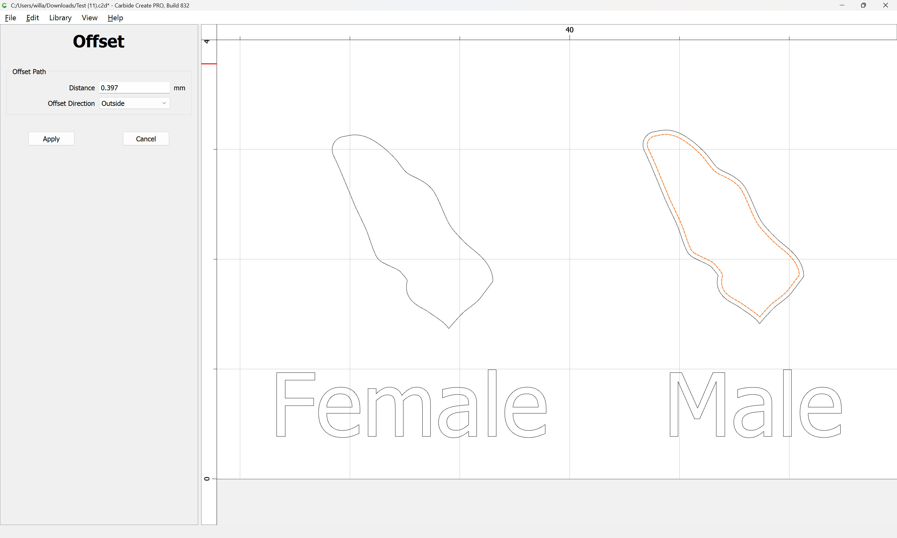
Apply
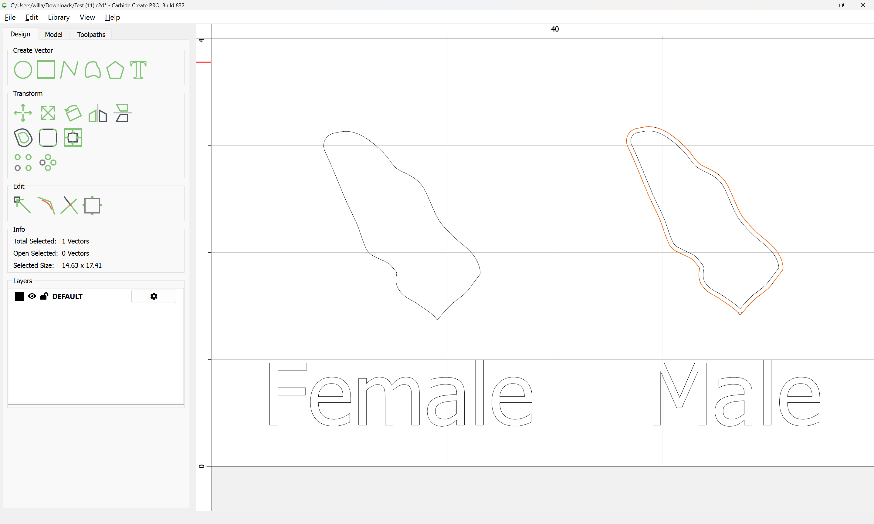
and use this same geometry for the pocket as well.
1 Like
As far as the mirroring I did not. Not sure why I needed to do it. As far as the Vcarve I did try it but stopped because it was looking for a Vcarve bit. I was not sure what to do at this point. I am open to either way. If you could take a look to see what I am doing wrong, I would appreciate it.
Thanks again for your help.
John
Test.c2d (608 KB)
Why are you using an inside offset for the pocket? I specifically noted that the same geometry had to be used. Copy-paste/duplicate it.
You need to create a shape which has the same appearance when cut on the inside or the outside — we had a lengthy discussion about this a while back:
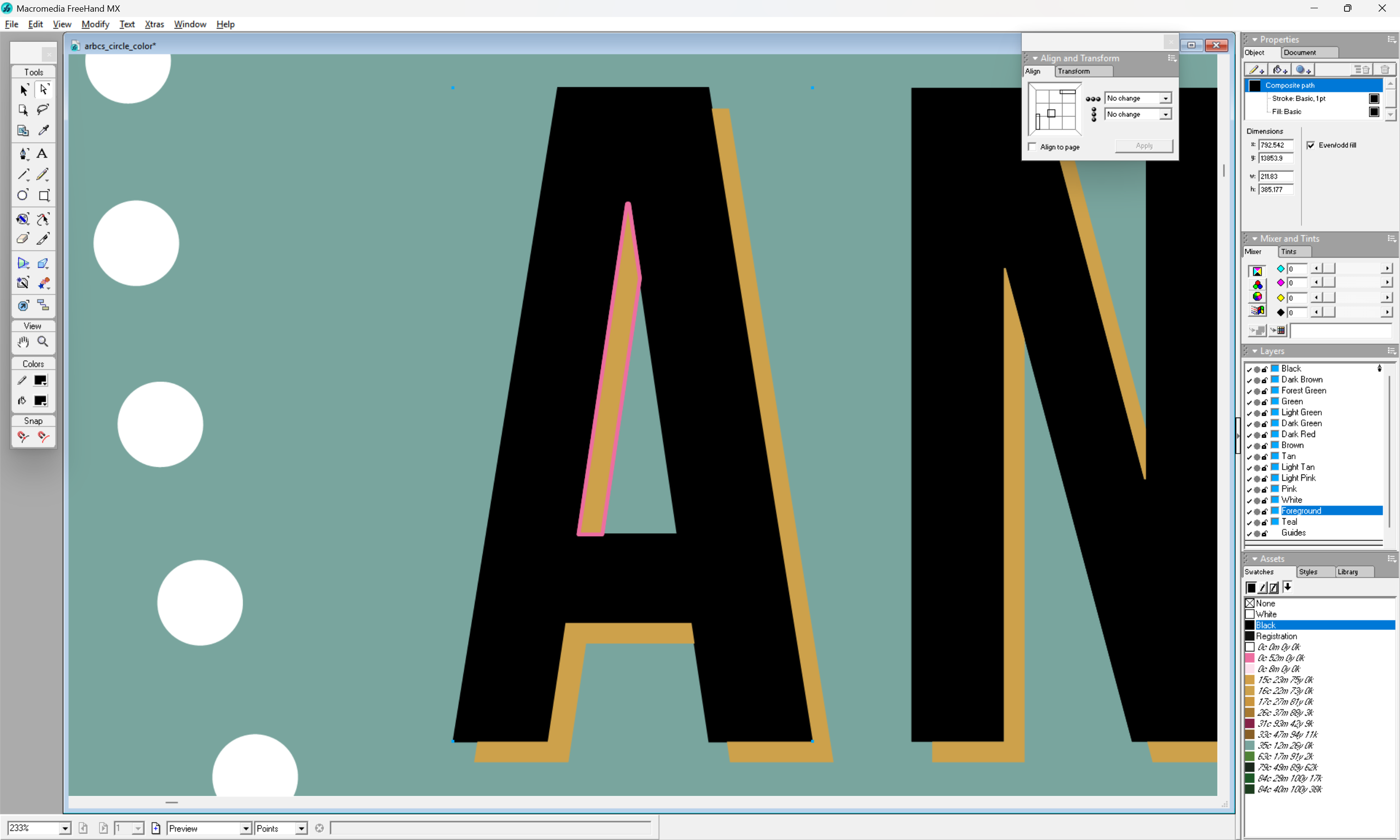
This is clearer if one uses a drawing program which will assign strokes/colours:
Imagine if we wanted to create a multi-colour inlay for a file such as:

1 Like
We will assume that we are using a very fine/delicate veneer — the usual approach with such is to stack two sections which will be interacting and cut them at a very slight angle so that the two pieces will fit together:

Note that if using a laser or a drag knife, there are specialty software programs for this such as:
A Carbide 3D #122 tool
has a cutting diameter of 0.03125 inches
If we add a rounded stroke of that thickness to an element:
We can see how it interacts with both parts — which becomes clearer if we instantiate this stroke:

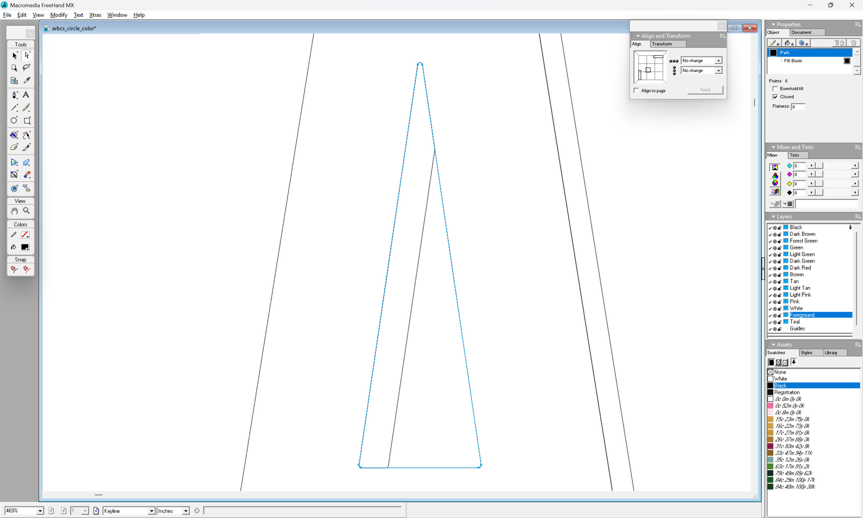
We need to create a version of this shape which fits to the inside — to achieve that, we inset to the inside by the radius of the tool:
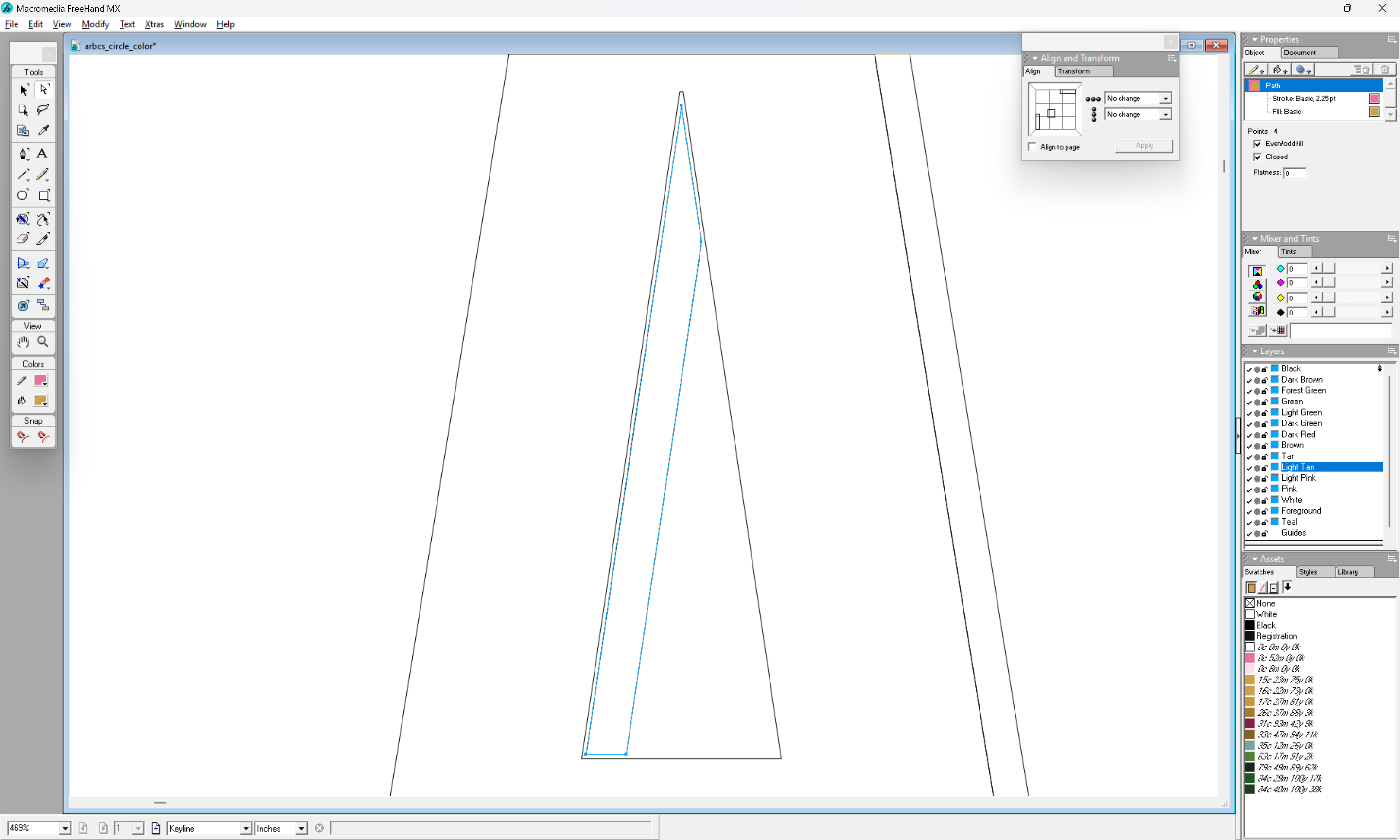
which when assigned a stroke:
u
matches up with the outer dimensions which we wish, and when instantiated as a closed region:
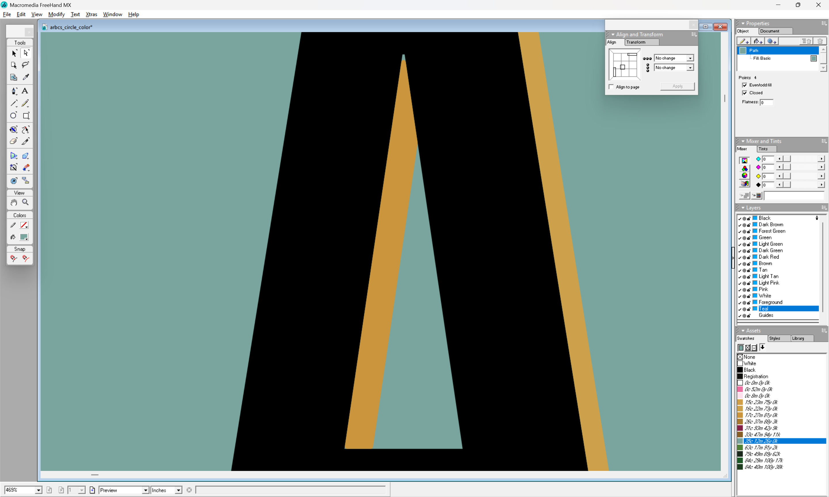
shows how the selected tool results in a distortion of the surrounding geometry (the teal shows through as an uncut region at the apex and lower left corner).
If we then increase the black region by duplicating this rounded form and using it for the counter of this letter A:
we can see that things will line up when cut:
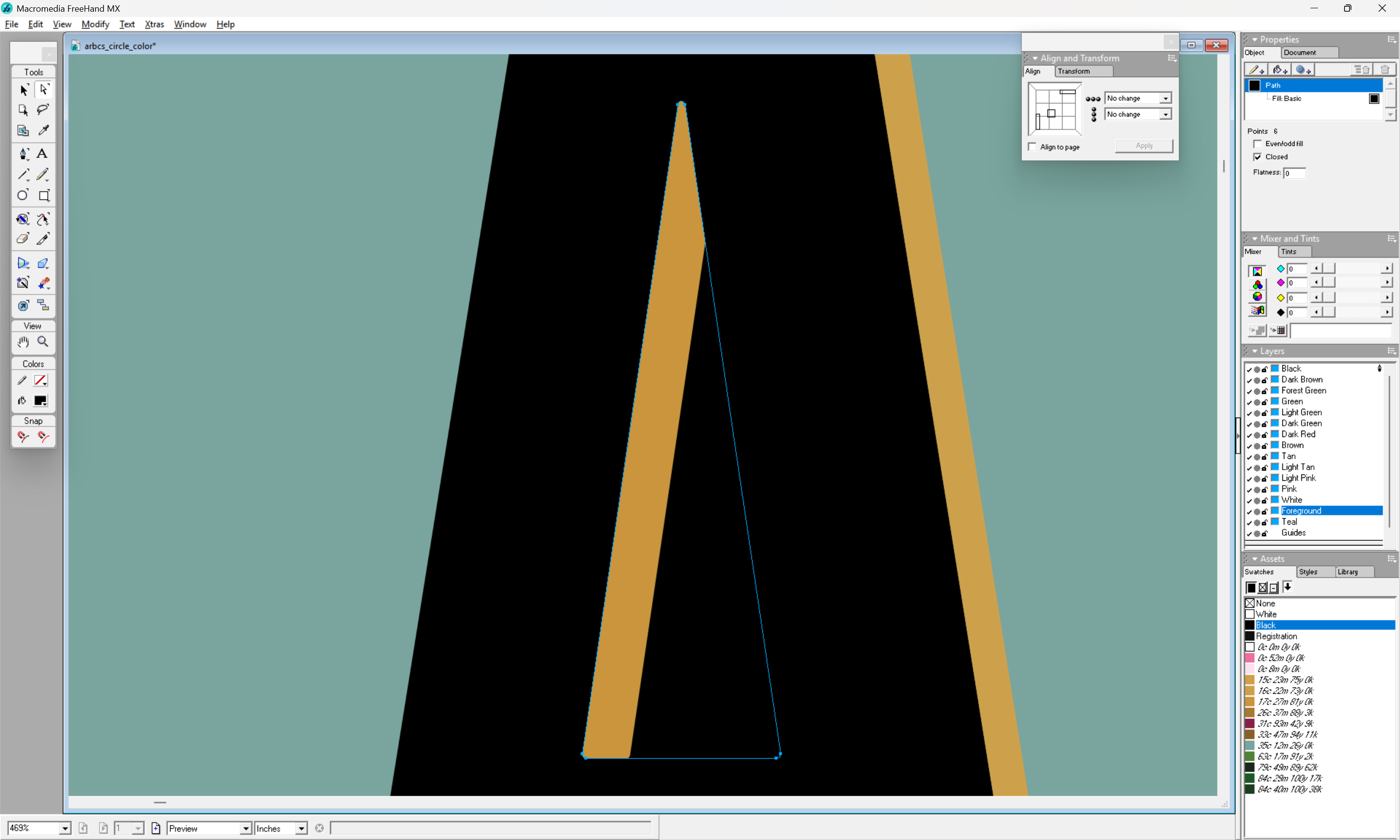
(except of course that the 3rd region cannot be cut thus due to the interactions of the rounded forms)
For more on this sort of thing see the manuals for vector drawing program or books such as:
1 Like
I am sorry I did not understand your previous instructions. Somethings do not come easy to me. Believe me when say, I do appreciate the help.
Without you guys I probably be packing it in.
John
1 Like
You will not. When your wife says she needs a stool for the bathroom: you make a stool for the bathroom.
Believe me. I was there. I am there.
The mirroring is necessary, since yo take the male part and turn it upside down. Try with a piece of paper, where you print your shape on. You leave one -the female or base part- on the table, and take the other one -the male or inlay, the one that should fit into the female (hence that moniker) part needs to be turned upside down, “mirrored”. Indeed, take some paper, gives you an impression, your sample test file appears as if the male part is not mirrored.
And then the “fun” part begins, fiddeling with the right measures: glue gap etc. If you use cylindrical (endmill) bits the whole thing must be very precise. Now with a 1/32 bit and 12 and 8mm cutting depth that is a challange for the bit: it pulls towards the cutting edge, and therefore will not stay straight. Hence one will experience less precision, and the parts do not fit nicely, or don’t fit in at all. Therefore think of using V-bits. These are more stable per depth due to the shape, and also due to the geometry of the cutting edge rather scrape off wood than really cutting it with a blade, therefore the bit does not pull itself into the wood, but rather pushes itself a little away. However one achieves an angled edge that may fit in better with some pressure with gluing. It fits -up to certain tolreances of course- better the more pressure one uses for gluing.
1 Like
Thanks for the words of encouragement. I’m trying my best and I can see the frustration when somebody tells you something and you just don’t understand. I’m frustrated with myself as well. I keep telling myself this is supposed to be fun. Most of the samples seem to be referring to V-Carve for inlays. I know they had made a lot of changes to the new and improved Advance V-Carve but unfortunately, some of the videos are out of date, which doesn’t help when you’re trying to learn something new. I will give the Advance V-Carve a try and see what happens. Thanks John
1 Like
John, check that video.
not only that is really educational, it also shows the mistakes even such an experienced professional like Kevin is not too proud to report, starts already at 11s.
1 Like
In regards to advance V-Carve. Depth is controlled by the distance between the lines. In my case, I was trying to create a pocket with a flat bottom and a plug that will fit into it. Maybe in my case I should not be referring to it as an inlay but a pocket and plug. V-Carve creates a V type cut.
I’m hoping to develop some additional interest but in any case I do appreciate your help.
Thanks again
John
This topic was automatically closed 30 days after the last reply. New replies are no longer allowed.