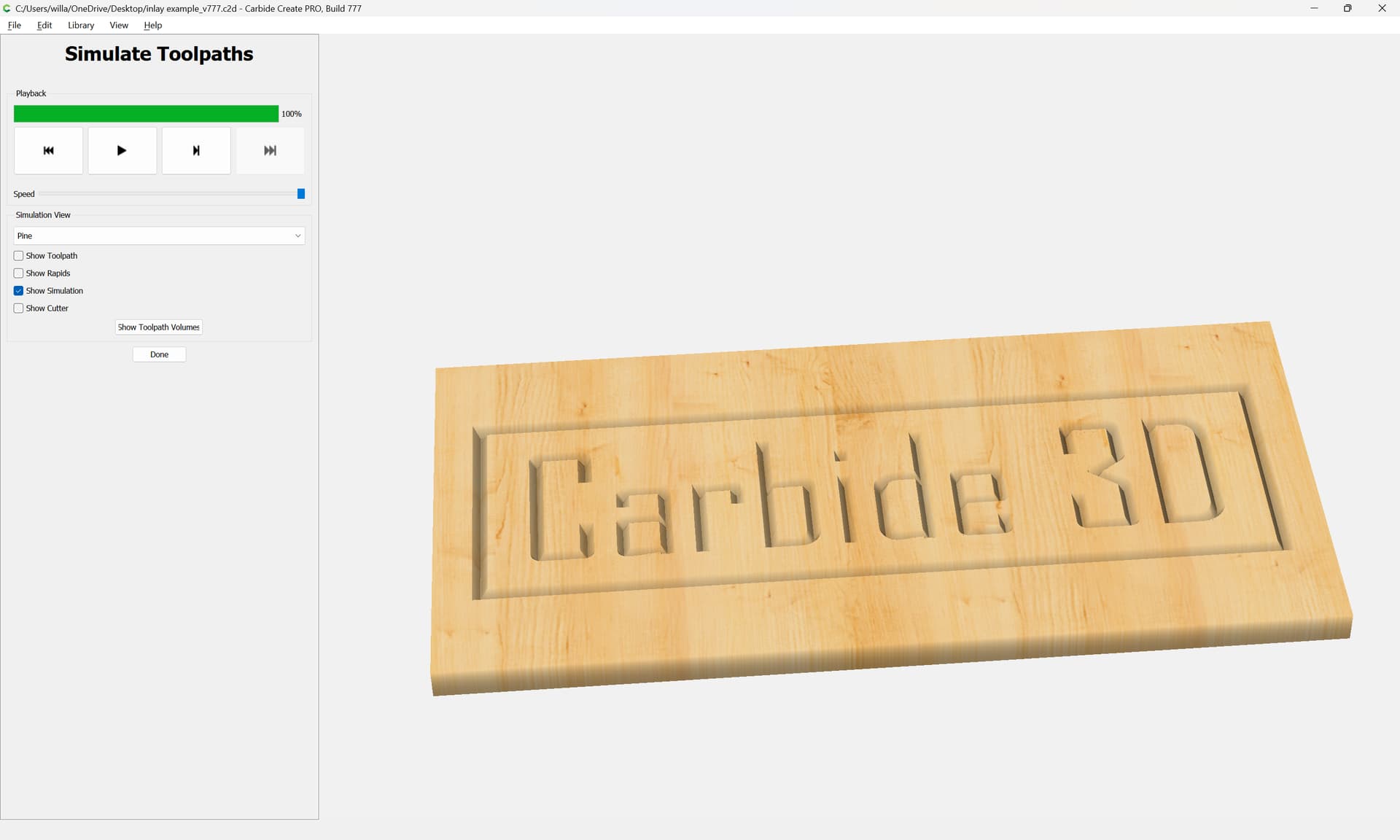
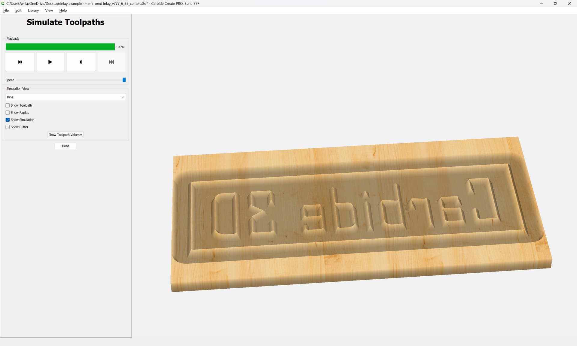
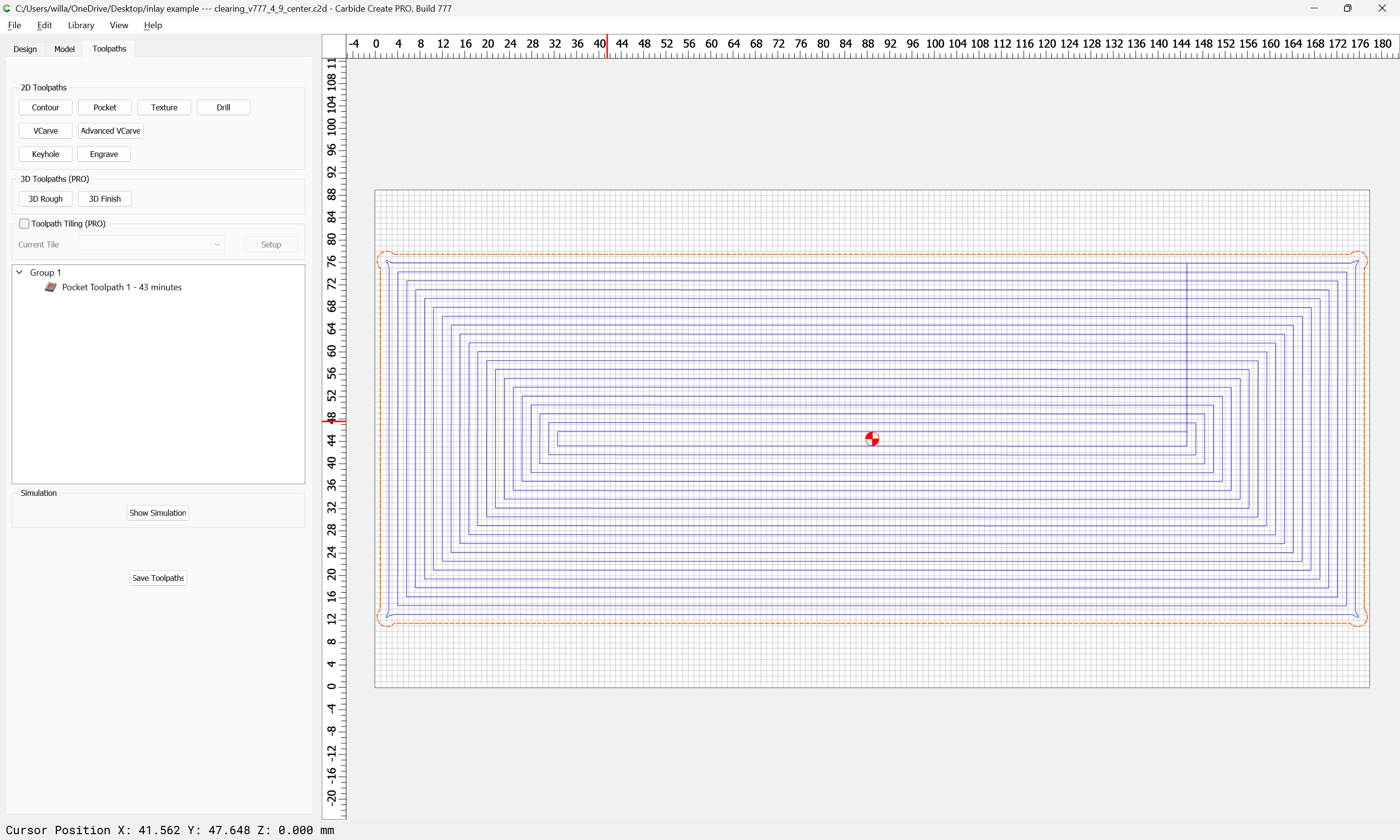
We just posted an update to Carbide Create with a rework of the inlay mode. This is a fundamentally different take on how to make inlays, so inlay toolpaths created with the old code will be reset back to a basic Advanced V-carve in this build. You’ll need to reenable the inlay mode and set the new parameters.
Some additional suggestions from our testing:
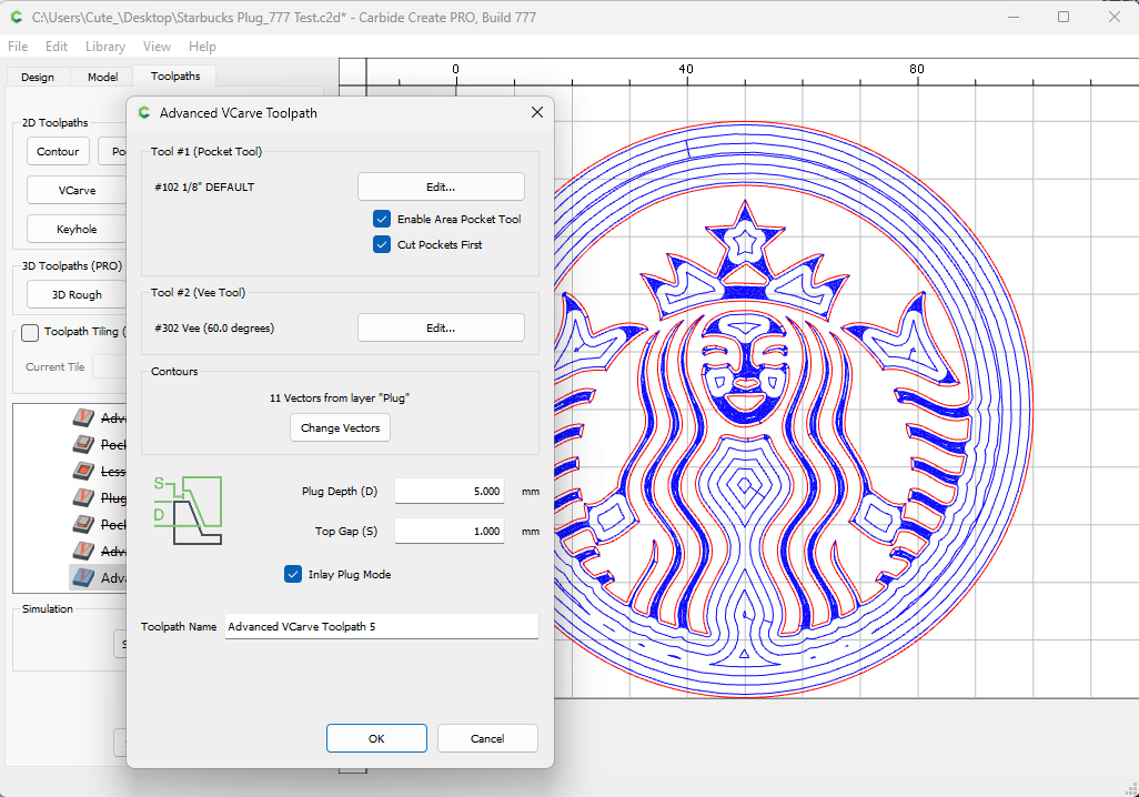
I would recommend making your inlay plug depth about 0.5mm less than the depth of your Advanced V-Carved pocket. That difference in depth is going to be your glue gap. You can probably go smaller with testing, but that’s a safe place to start.
I would also recommend a Top Gap of about 1mm. This is going to be your margin if your pocket is a tad oversized (which it will be if your V-bit doesn’t come to a perfect point), and your plug needs to drop into the pocket a smidgen more.
The toolpath is different than what we did in prior versions. The inlay will fit and it more closely follows the method that people have been using for V-carve inlays for years.
I’d like to make a suggestion for the ‘Inlay Mode’ - add an option to ‘automatically’ mirror the output.
That would allow the use of the exact same vectors for both the male and female side - less opportunity to mess up while developing the inlay, and it also makes it easier to have both the male and female toolpaths in one file - since both would use the same vectors, you don’t have to mess with layers for the male and female vectors.
In the editing mode, ‘Mirror’ basically does it ‘in place’. If inlay mode did the same, I think it would work as expected.
I have myself forgotten to mirror. However, what do you mirror around and how should that be aligned to stock origin etc? The more I their about it the less trivial it seems.
Usually the inlays are kind of “self contained” so we could mirror them about their center, and even add an offset boundary. I’m not sure we wouldn’t be opening a new can of worms though.
The CC mirror command looks like it creates a bounding box for the vectors, then flips left-to-right about the center of the bounding box.
I would expect a ‘Mirror option’ to behave identically. This preserves the relationship of the vector to the origin (or at least, the relationship of the bounding box of the vector, to the origin).
I keep hoping for rest machining in advanced Vcarve. It could improve the speed and finish quality considerably, and would not be particularly complicated to implement.
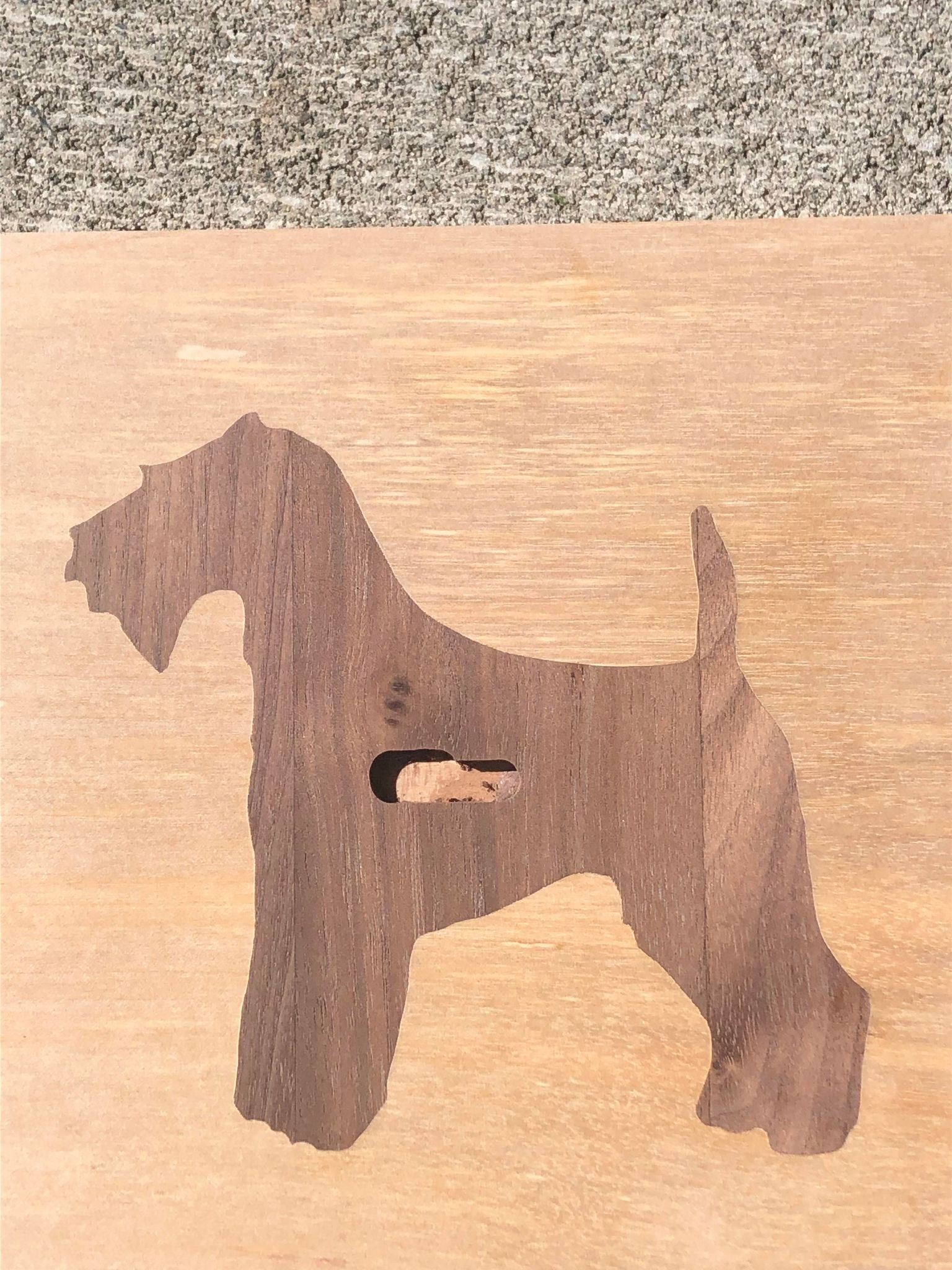
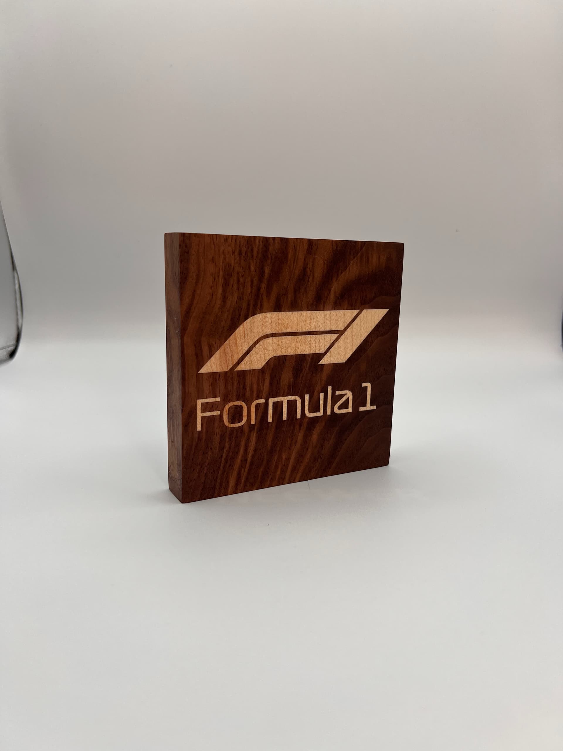
This is my FIRST ever attempt at an inlay. The new mechanism seems to work very well. The only ‘special’ thing I did was I used a down-shear 60 deg bit instead of the usual 60 deg geometry. The inlay is about 5"x4.5".
Ignore the hole in the center, that’s a problem with CM.
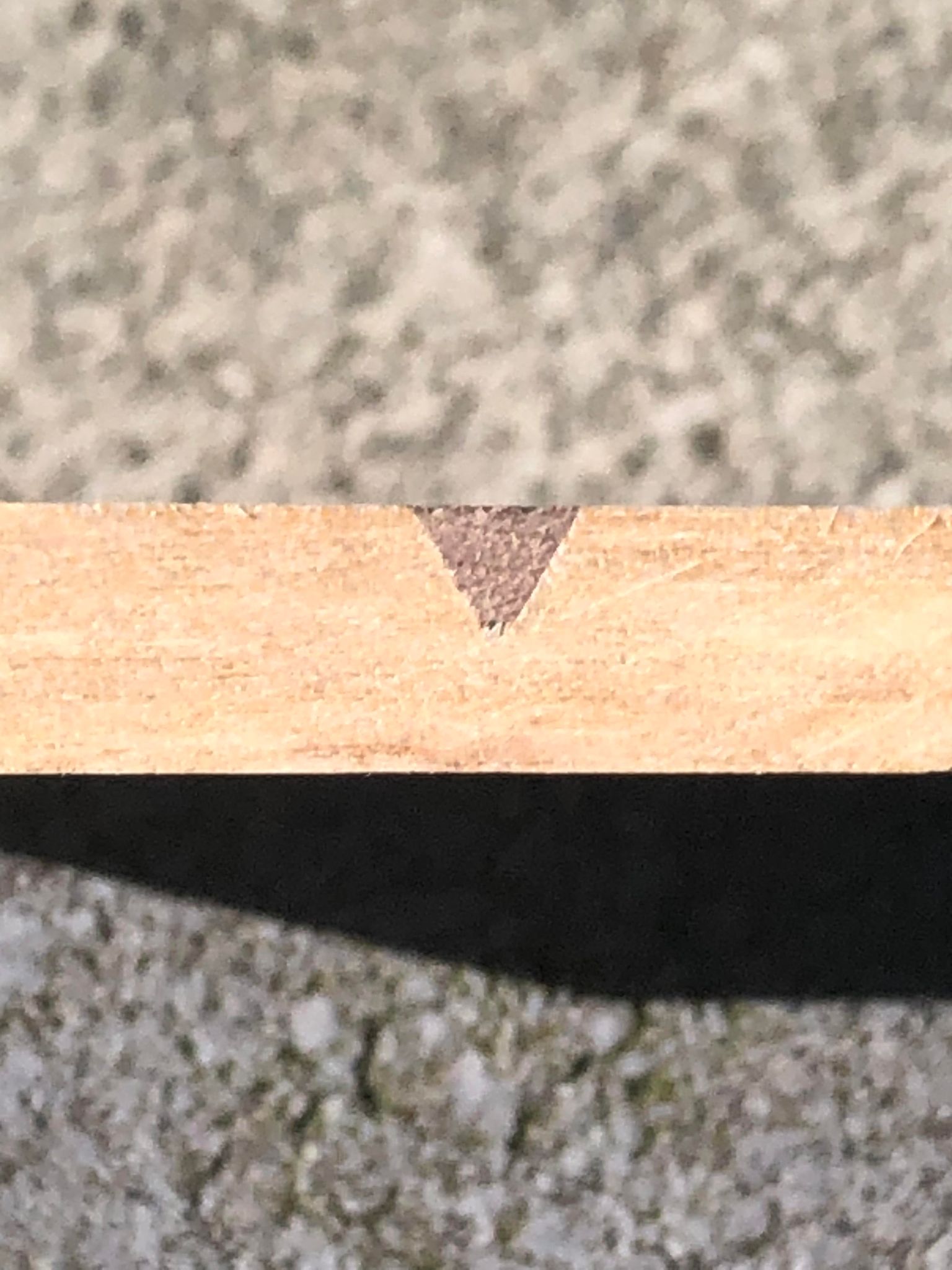
Cross section view. Total thickness is 9mm. I had settings for a 0.5mm glue gap, but ended up being closer to 1mm. Didn’t seem to affect anything else:
With the appropriate strategy I think the tiny side text could also be inlayed. This would involve using a #502 PCB Mill.
Random Notes:
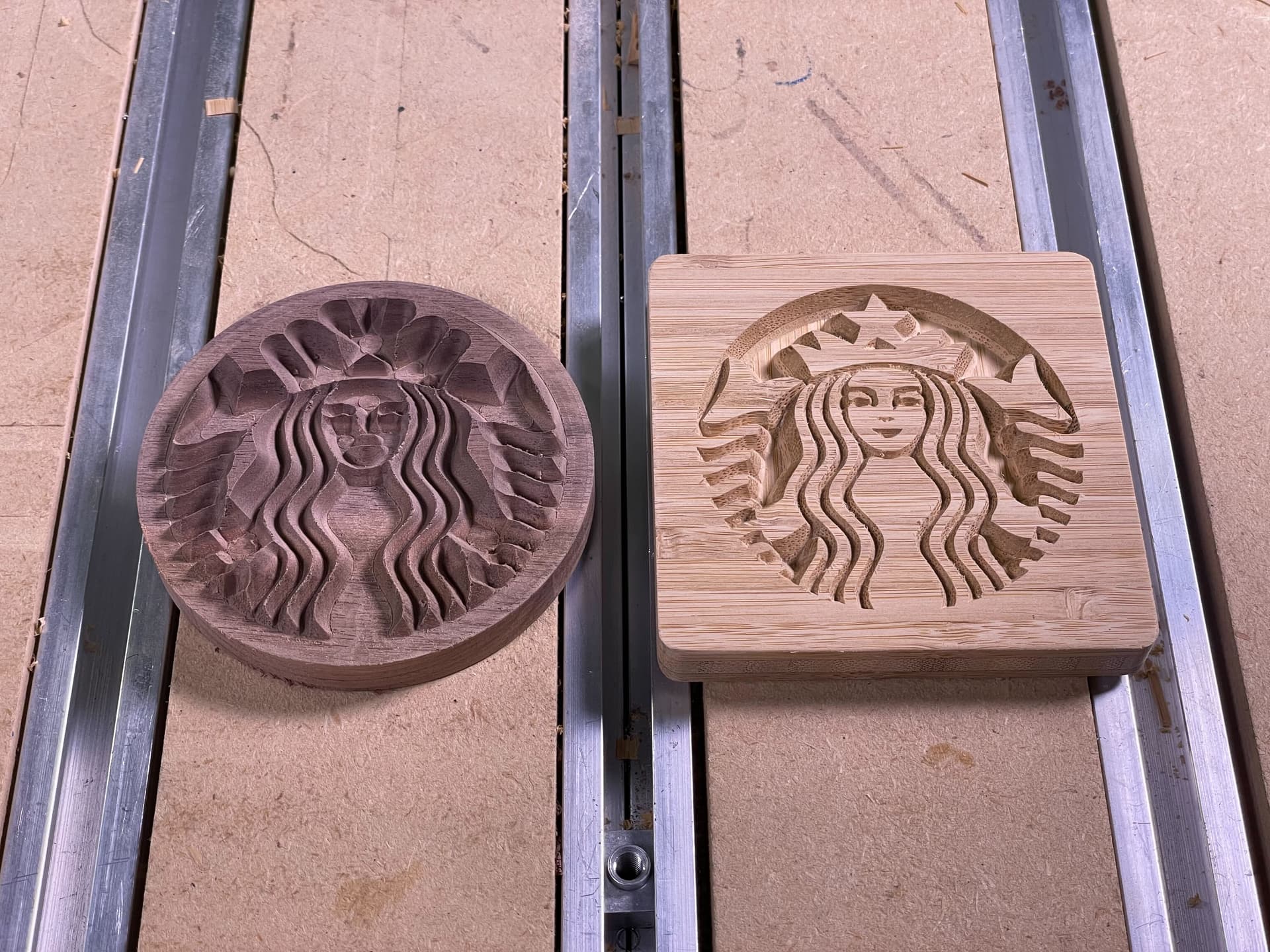
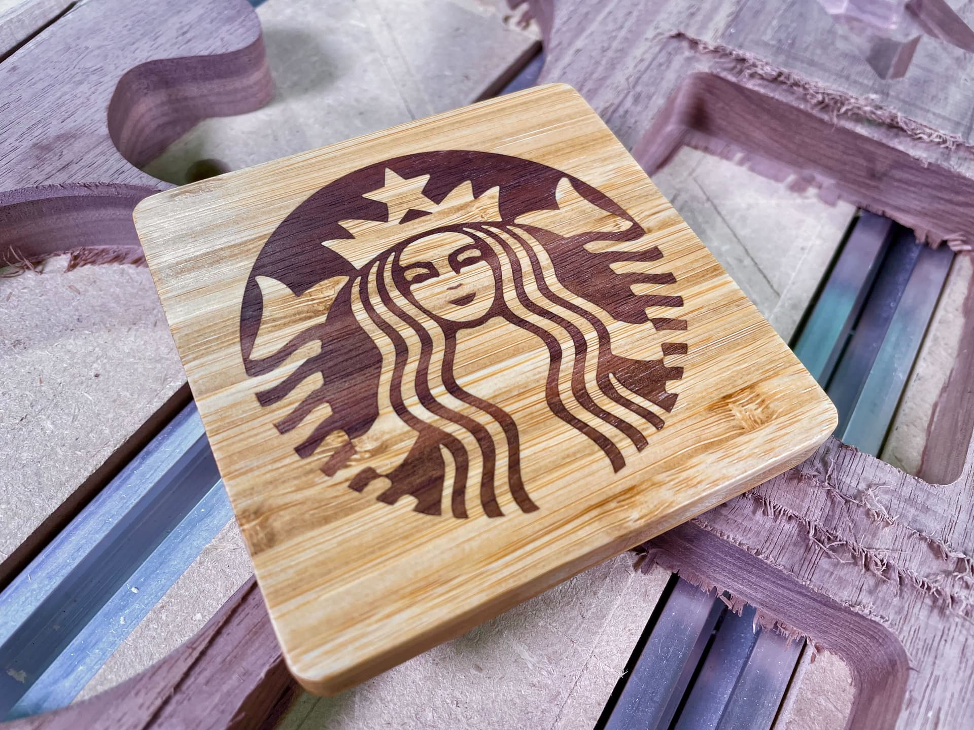
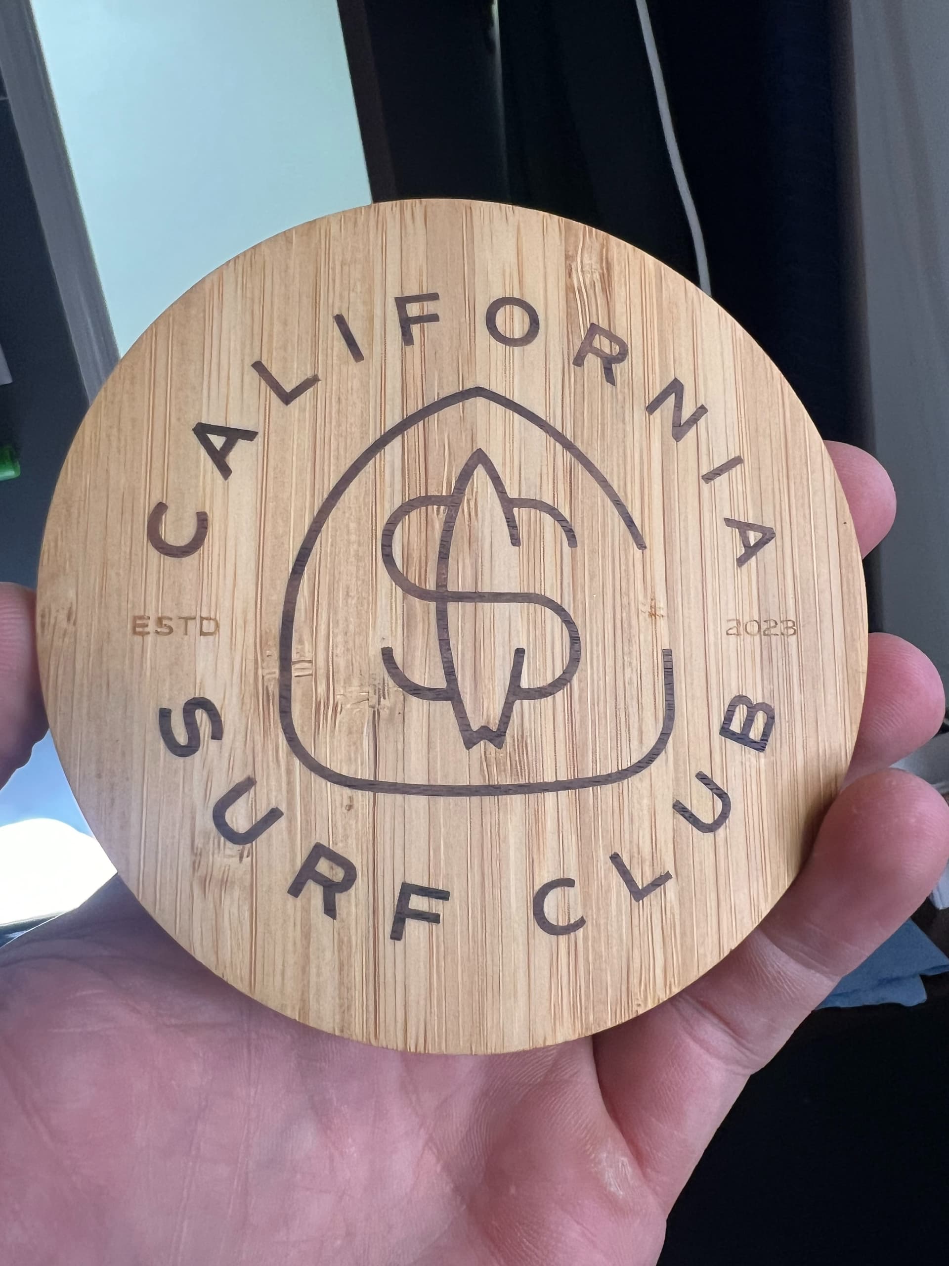
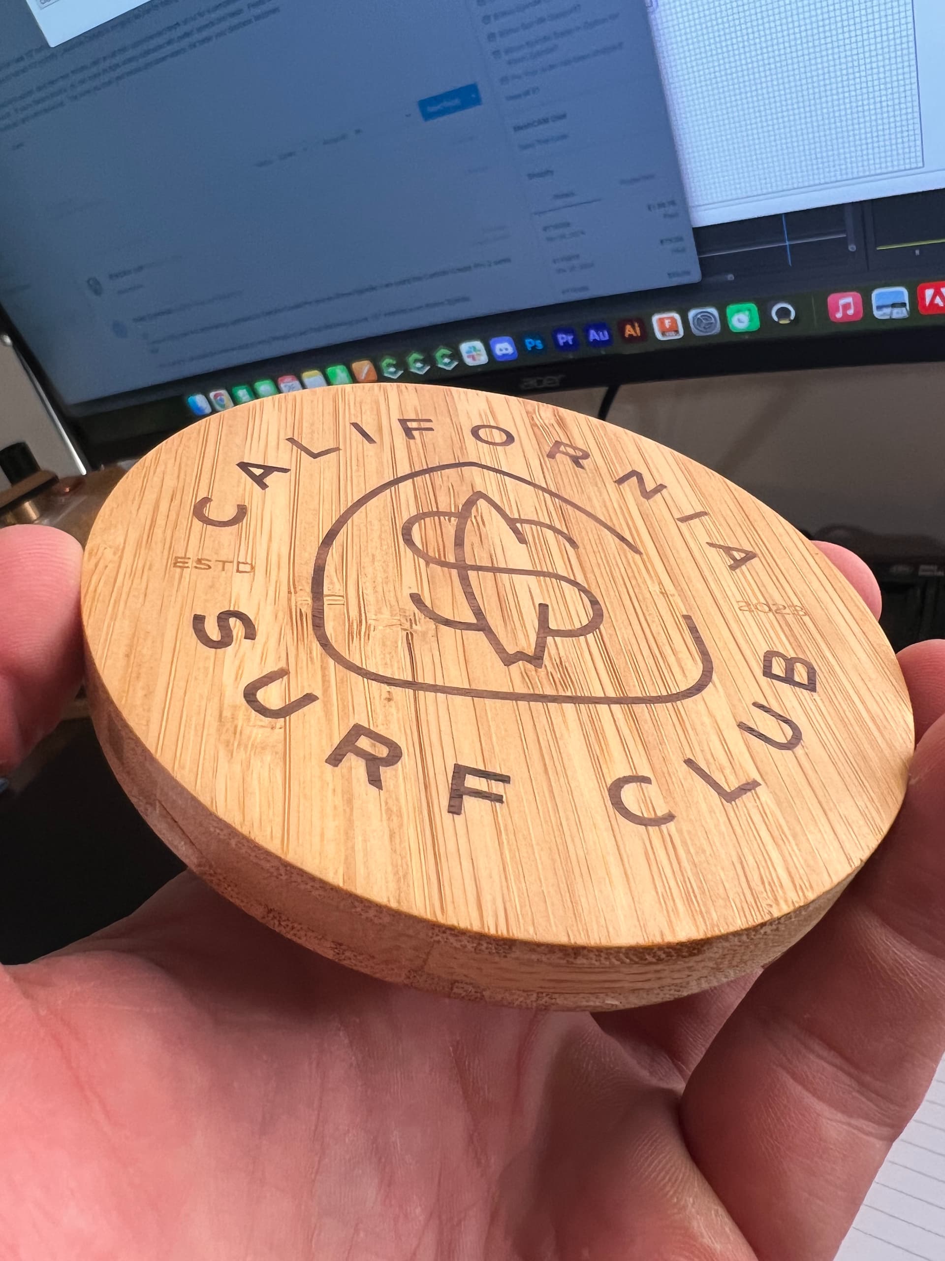
An all face grain project
Walnut inlayed to Bamboo Plywood
4.25" diameter
Cutter #302 60° V-Bit
I slowed my speeds and feeds to about 1000mm at 20000 RPMs to try and avoid losing the delicate fins of the plug.
Faced down to approximately .5mm above the surface and sanded from there.
Even though I lost the top fin of a “U” the final product featured no gaps.
The resolution of your plug material is going to matter greatly as you make finer details for the inlay. I believe maple will yield even better details than walnut on the plug side. End grain would allow both woods to perform at an even higher level of detail. Don’t forget to mirror your plug…Ask me how I know
I did an inlay recently (before this new mode) and it seemed to me that there should be a way to come up with a formula for the minimum width between vectors given the tool geometry and depth of cut / glue gap etc…
I have not seen it talked about before though so maybe I am oversimplifying it.
It took me several tries adjusting the vectors to get something that worked properly.
Unfortunately, part of gluing things up includes selecting an appropriate glue and waiting sufficiently long enough for it to cure — as much as I like using hide glue, this probably is not a suitable application for this, and I would suggest using some other adhesive.
I just saw that CC added a “top gap” to the new inlay feature. Great job! I got serious brain trauma from trying to figure out the multiple steps needed to do inlay with the previous version without inlay.
This was a late change to V7, and we’re eager to start working on bigger changes that will necessitate a change to the file format. Once that happens, we’re working on V8 and there won’t be any changes to V7. We’d love to get more feedback on the inlay code before we burn those ships.